Table of Contents

Related Manuals for Trianco AZTEC 6


Summary of Contents for Trianco AZTEC 6
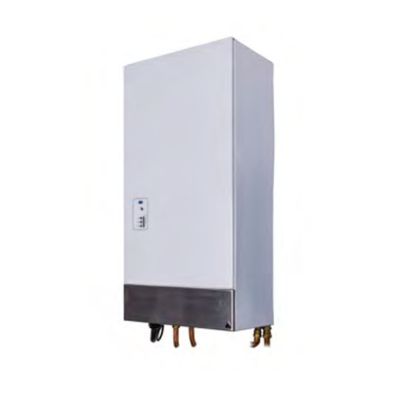
- Page 1 AZTEC 6, 9 & 12kW WALL HUNG MAXI COMBINATION BOILER INSTALLATION, OPERATION AND SERVICING INSTRUCTIONS Please read these instructions carefully before installing and operating this appliance TO BE RETAINED BY THE HOUSEHOLDER...
-
Page 2: Table Of Contents
CONTENTS PAGE HEALTH AND SAFETY PRE-INSTALLATION NOTES AFTER SALES SERVICE INTRODUCTION IMPORTANT SAFETY NOTES USER INSTRUCTIONS SIMPLE FAULT FINDING TECHNICAL DETAILS INSTALLATION VENTILATION REQUIREMENTS WATER SYSTEM 11 - 12 SEALED WATER SYSTEM REQUIREMENTS 12 - 14 WIRING INSTRUCTIONS WIRING DIAGRAMS SERVICING PART REPLACEMENT 16 - 17... -
Page 3: Health And Safety
HEALTH AND SAFETY INFORMATION FOR THE USER, INSTALLER AND SERVICE ENGINEER Under the Consumer Protection Act 1987 and the Health and Safety at Work Act 1974, it is a requirement to provide information on substances hazardous to health (COSHH Regulations 1998). TR Engineering takes every reasonable care to ensure that its products are designed and constructed to meet these safety requirements when the products are properly installed and used. -
Page 4: Pre-Installation Notes
These instructions should be kept in a place close to the appliance for easy reference. IMPORTANT PRE-INSTALLATION NOTES Before installation, it is imperative that the following guidelines are heeded to ensure the trouble-free and efficient operation of the boiler: Ventilation and Siting When siting the boiler in a confined space it is essential that adequate ventilation be provided. -
Page 5: After Sales Service
BY TR ENGINEERING LTD. NOTE: Over 50% of all service calls made are found to have no appliance fault. Register your boiler online www.trianco.co.uk/product-registration SERVICE CENTRE AND TECHNICAL SUPPORT Tel: 0114 257 2300 Fax: 0114 257 1419 Hours of Business Monday to Thursday 8.30am - 5pm... -
Page 6: Introduction
We recommend that you keep these instructions in a place near your appliance for easy reference. The Trianco Aztec Combination Wall Mounted Boiler has been designed to conform to European Directive/Standards EN60335-1:2002 +A15:2011, EN60335-2-35:2002 inc Amd 1, EN55014-1:2006 +A1:2009, EN55014-2:1997 +A2:2008. -
Page 7: User Instructions
USERS INSTRUCTIONS BOILER INDICATOR LIGHT The Trianco Aztec Combination boiler has been designed There are twelve LED indicator lights on the boiler fascia and constructed to give years of trouble-free service and panel these are: these instructions are provided to assist you in obtaining LED 1 GREEN Power to the boiler. -
Page 8: Simple Fault Finding
SIMPLE FAULT FINDING Amber light illuminated or flashing. If the boiler fails to start for no apparent reason, make the Check to see if all external controls i.e. programmer or following checks before calling your service engineer. room thermostat is calling for heat. Is the green LED light illuminated? Resetting the boiler Check for blown fuse or thrown power breaker. -
Page 9: Installation
NOTE: ALWAYS STORE THE BOILER IN A DRY PLACE PRIOR TO FITTING. SITING THE BOILER IMPORTANT: NOT TO BE INSTALLED IN A SHOWER COMPARTMENT OR BATHROOM Ensure adequate clearance is allowed for making water connections. Access is required to the front and the top of the boiler for servicing. - Page 10 Fig 1.2...
-
Page 11: Ventilation Requirements
VENTILATION REQUIREMENTS IMPORTANT: ENSURE ALL SERVICE VALVES ARE IN OPEN POSITION. If the appliance is to be fitted in a confined space or The boiler is supplied with Dia. 22mm tail pipes at the compartment it is a requirement that adequate ventilation base of the boiler for connection to the heating system is provided to prevent the overheating of the boiler (see Fig: 1). -
Page 12: Sealed Water System Requirements
NOTE: Failure to ensure the correct vessel size could SEALED WATER SYSTEM REQUIREMENTS result in premature failure of the expansion vessel which in turn may adversely affect other components in the The installation must comply with the appropriate system i.e. circulating pump and diverter valve. requirements of the current issue of BS4814, BS5449, BS6798 and BS7074 Part 1 and 2. - Page 13 Fig 3 AZTEC COMBI SCHEMATIC LAYOUT CENTRAL HEATING MODE Pump Plate Heat Exchanger Expansion Boiler Boiler Vessel Flow Switch Diverter Valve C/H Return C/H Flow Fig 4 Cold Inlet AZTEC COMBI SCHEMATIC LAYOUT DOMESTIC HOT WATER MODE Fig 5 SEALED SYSTEM PIPING SCHEMATIC DIAGRAM...
-
Page 14: Wiring Instructions
The 12kW boiler must be installed in premises having a ALTERNATIVE METHODS OF system impedance of not more than 0.1939 + 0.1939Ω. FILLING A SEALED SYSTEM A double pole RCD with a trip level sensitivity of 30ma can be used capable of breaking full load current to BS EN61008: 1994 NOTE: RCD unit can be used as the isolating switch if mounted close enough to the boiler. - Page 15 Fig. 9 Internal Wiring diagram...
-
Page 16: Servicing
SERVICING Disconnect the remaining red and black power cables from the PCB. To ensure reliable operation of your Aztec electric Finally remove the 2 fixing screws holding the PCB combination boiler, it is recommended that you have your mounting bracket in position and remove the PCB from the boiler serviced once a year. -
Page 17: Fault Finding
Thermistor ELEMENT REPLACEMENT The boiler has two thermistors fitted, one on the heat Isolate electrical supply to boiler. exchanger and one on the tank. The heat exchanger thermistor is fitted to the front top of the heat exchanger Drain down system. and secured in position with a clamp, the other end terminates with a white connector that plugs on to the PCB Disconnect terminal connectors from high limit... - Page 18 Green LED Element Jumper Connections If the green LED is illuminated but the boiler is not functioning, check that the external controls fitted are calling for heat. Blown Fuse on Board The fuse is located at the top of the PCB (fuse type 20mm 1000Ma anti surge) The fuse covers external controls.
-
Page 19: Fault Finding Flow Charts
NO HEAT - PERMANENT GREEN LIGHT IS THE PROGRAMMER TURNED ON I.E. CALL SIGNAL? CHECK IS CALL WIRE LIVE I.E. LINE ELECTRIC VOLTAGE? SYSTEM CIRCUIT CHECK EXTERNAL CONTROLS ARE CALLING FOR HEAT IS THE HEAT EXCHANGER GETTING UP TO TEMPERATURE - AMBER ON OR FLASHING? CHANGE PCB OPEN... - Page 20 PERMANENT RED LIGHT IS INCOMING POWER SUPPLY OK? DOES THE BOILER GO STRAIGHT TO RED LIGHT? CHECK INCOMING SUPPLY DOES THE BOILER GO CROSS POLARITY? FROM GREEN TO CORRECT VOLTAGE? AMBER THEN RED? CORRECT RCD? HAS THE HIGH LIMIT STAT TRIPPED? RE-SET HIGH LIMIT STAT ARE THE LIMIT...
- Page 21 NO GREEN LIGHT IS THERE POWER TO THE BOARD? CHANGE FUSE HAS THE FUSE HAS THE RCD AND CHECK BLOWN ON THE RESET RCD TRIPPED? PUMP PCB? IS THERE CHANGE PCB POWER TO LIVE AND NEUTRAL? CHECK SYSTEM WIRING FLASHING RED LIGHT ARE CABLES REPLACE CABLES...
- Page 22 ITEM PART No. DESCRIPTION QUANTITY HEATER BODY W.U. 221850 3kW ELEMENT 221807 GASKET ELEMENT FLANGE W.U. BOTTOM FLANGE W.U.
-
Page 23: Spares/Exploded View
ITEM PART No. DESCRIPTION QUANTITY 226216 Left Hand Side Panel 226212 Top Panel 226207 Back Panel 226215 Front Door 226216 Right Hand Side Panel 226211 Control mounting Plate 226209 Bottom Panel 226210 Front Hinged Panel... - Page 25 ITEM PART No. DESCRIPTION QUANTITY 211890 Printed Circuit Board 226221 Printed Circuit Board Mounting Bracket 221825 High Limit Thermostat Thermistor Wiring Harness complete 4 Pole Relay 2 Pole Relay High Limit Thermostat Wiring Harness PCB Mains Wiring Harness PCB to Relay Wiring Harness Relay to Element Wiring Harness Mains terminal block Temperature Control Buttons &...
- Page 26 S35 2PH Tel: (0114) 2572300 Fax: (0114) 2571419 www.trianco.co.uk © TR Engineering Limited Copyright in this brochure and the drawings and illustrations contained in it is vested in TR Engineering Limited and neither the brochure or any part thereof may be reproduced without prior written consent.
Need help?
Do you have a question about the AZTEC 6 and is the answer not in the manual?
Questions and answers