Table of Contents

Related Manuals for Trianco GREENFLAME 55


Summary of Contents for Trianco GREENFLAME 55
-
Page 1: Servicing Instructions
GREENFLAME 55/85/100/125/199 kW Commercial Wood Pellet Boiler System INSTALLATION, OPERATION AND SERVICING INSTRUCTIONS Please read these instructions carefully before installing and operating this appliance. TO BE RETAINED BY THE HOUSEHOLDER... - Page 2 Sheffield S35 2PH United Kingdom Tel: 0114 2572300 Fax: 0114 2571419 E-mail: info@trianco.co.uk Web: www.trianco.co.uk SAFETY NOTICE PLEASE READ THIS ENTIRE MANUAL BEFORE YOU INSTALL AND USE YOUR NEW BOILER. THIS APPLIANCE MUST BE INSTALLED BY APPROVED AND COMPETANT PERSONNEL ONLY. FAILURE TO INSTALL THE APPLIANCE IN ACCORDANCE WITH THE MANUFACTURERS INSTRUCTIONS AND LOCAL BUILDING REGULATIONS AND BY-LAWS WILL INVALIDATE THE WARRANTY.
-
Page 3: Table Of Contents
Table of Contents General Information Important note for efficient and low-emission operation of your Greenflame biomass heating system. Safety Information Greenflame Safety Guidelines Greenflame System Features Greenflame Boiler Features Fillomatic Pellet Transport Features Self Cleaning Burner Features Control System Installation Setting out the boiler location Unpacking Assembly... - Page 4 Table of Contents 5.6.1.7 Language Menu 5.6.2 Keyboard Menu 5.6.3 Secret Menu Troubleshooting How Does My Wood Pellet System Work Sensors Combustion Process What Happens When I Turn On My Boiler 7.3.1 Check-Up 7.3.2 Pre-Heating 7.3.3 Pre-Load 7.3.4 Variable Ignition 7.3.5 Stabilisation 7.3.6...
-
Page 5: General Information
1. General Information Dear Customer, We would like to congratulate you on choosing this high-quality product from TR Engineering Ltd. The Greenflame range of wood pellet boilers for commercial / light industrial applications are designed specially with aim of maximising efficiency, reduced CO2 emissions, compact design for installation in the smallest of plant rooms and cutting edge system management features with remote access through the cellular network for remote routine maintenance, as standard. -
Page 6: Important Note For Efficient And Low-Emission Operation
1.1 Important note for efficient and low-emission operation of your TR Engineering Ltd biomass heating system. For efficient and low-emission operation of your TR Engineering Ltd heating system, please follow these instructions: • Only use the fuels specified in this TR Engineering Ltd instruction manual. Only then can a low-emission, economic and trouble-free operation of your heating system be guaranteed. -
Page 7: Safety Information
• In the case of any problems contact your Agent or for Troubleshooting visit www.trianco.co.uk . Legislation stipulates certain devices should be used with automatic pellet boilers which prevent back-burn along the conveying troughs into the fuel store. The following safety precautions are implemented in TR Engineering Ltd systems: •... - Page 8 HEALTH AND SAFETY PRECAUTIONS Special care must be taken when installing the boiler such that the requirements of the Health and Safety at Work Act are met. Handling Adequate facilities must be available for loading, unloading and site handling. Fire Cement Some types of fire cement are caustic and should not be allowed to come into contact with the skin.
-
Page 9: Greenflame System Features
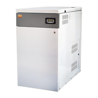
3. Greenflame System Features The data plate contains important information on the type designation of the appliance. You will find this on your system mounted on the control panel cover . The boiler is located on the left hand side of the unit with the burner located underneath the integral storage hopper. -
Page 10: Greenflame Boiler Features
3.1 Greenflame Boiler Features The heat exchanger has been designed and developed to provide maximum efficiency and combustion quality as well as not having to compromise on space. The compact nature of it’s design has allowed the integral hopper to be incorporated as part of the overall unit. -
Page 11: Fillomatic Pellet Transport Features
3.2 Fillomatic Pellet Transport Features The integral hopper has a capacity of up to 125 kgs of pellets. Filling of the hopper is carried out automatically by the Fillomatic pellet transport system. The pellets are auger fed from the base of the hopper to the top of the drop feed pipe where the pellets free fall into a cell wheel and down into the pellet burner. -
Page 12: Self Cleaning Burner Features
3.3 Self Cleaning Burner Features The self cleaning burner system allows the burner to maintain optimum combustion by maintaining the combustion tube in a clean condition. The cleaning process is activated after each time the system goes into an extinguishing phase (or after a number of run cycles as required). -
Page 13: Control System
3.4 Control System The TR Engineering Ltd Greenflame Control System leads the way in combustion efficiency and control and is also at the cutting edge in communications technology and providing the user with useful information related to their Greenflame system. The main features of the Greenflame control system include : •... -
Page 14: Installation
4. Installation Careful consideration and time spent planning the boiler room and fuel store will prevent delays when it comes to installing the system. It is recommended that a survey of the plant room should be forwarded to TR Engineering Ltd for review so they can advise the best solution for locating the boiler and fuel transport systems. -
Page 15: Unpacking
4.2 Unpacking The TR Engineering Ltd Greenflame Pellet Boiler System is delivered in a single crate. Remove the wooden crate, cardboard packaging, polystyrene packing, and bubble wrap packaging and recycle in the appropriate manner. The following items should accompany you Greenflame pellet boiler system : Fillomatic Pellet Transport System ... -
Page 16: Assembly
4.3 Assembly The Greenflame is supplied fitted to it’s base permanent base for ease of lifting and assembly. The Greenflame boiler is “plug and play” with just the connection of the flue, hydraulic system and electrical system. The only items that need to be fitted to the Greenflame are the ash box, exhaust fan housing and the pellet cyclone. -
Page 17: Flues
4.4 Flues Use stainless steel twin walled insulated flue pipe to flue your Greenflame. An exhaust fan is used to extract the combustion gases from the firebox. This creates a negative pressure in the firebox and a positive pressure in the flue system. The longer the flue pipe and more elbows used in the system, the greater the flow resistance. - Page 18 Chimneys taller than 6m above the connection will require a draft test to determine if the draft is too high. Note: The High Burn Draft should not exceed 50Pa. A draft stabiliser is fitted to the starter flue to counteract a certain amount of excessive draft but additional measures may be required.
-
Page 19: Flue Requirements
4.6 Flue Requirements A natural draught must exist in the boiler when connected to the flue and this will be checked by the Commissioning Engineer before the burner is run. If this is not the case then the customer must take the necessary measures to ensure a draught like increasing the flue height or fitting an anti downdraught cowl. - Page 20 The chimney or flue must have a cross-sectional area throughout its whole length that is at least the area of flue outlet of the boiler and must be sealed to the boiler with fire clay or other suitable compound. The chimney or flue should be of sufficient height to provide draught of min. 25Pa measured at the test hole in the top of the boiler.
- Page 21 Opening of the flap on the regulator differs depending on the adjustment as well as the draught in the chimney. The draught varies considerably depending on the chimney, the weather and if the burner runs or not. This means that the function can vary between different installations, e.g.
-
Page 22: Air Supply
4.7 Air Supply Free Air Requirements - Provision for air for combustion and ventilation: General: A sufficient permanent air supply to the appliance will be required for: (a) Correct combustion of fuel an effective discharge of combustion products to the open air. - Page 23 The warranty for such boilers could be affected if proper free air requirements are not provided. TR Engineering Ltd recommend that two air vents should be provided into the room containing the appliance. One should be located at least 100mm above finished floor level and the other at high level.
-
Page 24: Water Connections
4.8 Water Connections The diagram below indicates the plumbing connections at the rear of the boiler. Two flow connections and two return connections to run separate circuits to the DHW cylinder and the heating. 2” BSP Flow 1” Drain 2” BSP Return It is recommended that the boiler is plumbed into open vented system (the maximum static head of water permissible is 90 ft. - Page 25 TR Engineering Ltd recommend the use of a buffer tank. Buffer tanks (direct cylinders) can achieve the optimum running of the system in terms of efficiency and running costs. Once the plumbing has been completed the system should be fully flushed to clear any debris which may have become lodged in the pipe work.
-
Page 28: Electrical Connections
4.9 Electrical Connections Electrical installations should only be carried out by suitably qualified and certified electricians. If in doubt on any issue relating to the electrical connections on the appliance contact TR Engineering Ltd Energy Technical Support or your Local Dealer for guidance before carrying out any connections. -
Page 29: Self Cleaning Burner Electrical Schematic
4.10 Self Cleaning Burner Electrical Schematic Combustion Fan Air Cleaning Solenoid... -
Page 30: Boiler Control Panel Electrical Schematic
4.11 Boiler Control Panel Electrical Schematic... -
Page 31: Digital Control System
5. Digital Control System The BMS (Boiler Management System) controls all functions of the boiler and associated hardware (i.e. circulation pump, mini hopper auger motor, exhaust fan, etc.). The control panel display indicates the system state at which the boiler is running in real time as well as providing the Customer with a user friendly way of adjusting temperature and identifying clearly any issues which may occur system. -
Page 32: Led's
5.2 LED’s FUNCTION DESCRIPTION Led On: HEATING RESISTANCE Resistance on Led On: AUGER 1 Auger in the interval ON Led On: PUMP Pump On Led On: ELECTROVALVE Electrovalve On Led On: PELLET LEVEL sensor reveals a lack of pellet Led On: Ambient Thermostat contact open OR EXTERNAL THERMOSTAT High Voltage Ambient Thermostat not... - Page 33 Information that can be seen on the Main Screen is: Date and Time Chrono activation Modality (D daily, W weekly, We week-end) Locked buttons User power selected or Automatic Power Selected recipe Functioning State System Error code Boiler Thermostat value Exhaust temperature Water temperature Flame On if Flame Light over L01...
-
Page 34: Power Display
5.4 Power Display DISPLAYED POWER IN AUTOMATIC MODE DISPLAY DESCRIPTION No power (OFF state or BLOCK state) or fans at max speed in CHECK UP state Variable Ignition or Stabilization Power Power 1 Power 2 Power 3 Power 4 Power 5 Extinguishing, Modulation or Standby Power 5.5 Error Messages ERRORS... -
Page 35: Menus
5.6 Menus In the BMS there are two levels of Menu , a USER MENU and a SECRET (INSTALLER) MENU. The USER MENU allows the User to perform some basic functions such as: 5.6.1 User Menu USER MENU DESCRIPTION Allows to User modify the combustion Power power if the controller is set to Manual Mode Menu which allows the User to modify the... - Page 36 To Enter the User Menu : Push P3 button to enter the user menu Using P4 and P6 buttons it is possible to select the desired menu or submenu. If a parameter value is changed, the new value is sent to the boiler controller. But if the transmission failures a message appears: and you need to modify again the parameter’s value.
-
Page 37: Power Menu
5.6.1.1 Power Menu Menu which allows the User to modify the system combustion power only if the system is set to Manual by the Commissioning Engineer 5.6.1.2 Boiler Thermostat Menu Menu which allows the User to modify the Boiler Thermostat’s value for Standby i.e. boiler SET temperature. -
Page 38: Monitor
5.6.1.5 Monitor Menu allows you to view the values as read by the system sensors. 5.6.1.6 Load Menu Menu allows you to load the auger manually. To enable the auger select ON To stop the auger select OFF or wait 600 seconds. (The seconds of activation are showed on the display) IT IS POSSIBLE TO LOAD THE AUGER MANUALLY ONLY IF THE SYSTEM IS OFF. -
Page 39: Keyboard Menu
5.6.2 Keyboard Menu This menu allows Technicians to test the panel connection and to update the product. Only Authorised Personnel should access this Menu. 5.6.3 Secret Menu This menu is for Service Technicians and Commissioning Engineers and contains all the parameters and settings for the system. -
Page 40: Troubleshooting
6. Troubleshooting Error Code Cause Remedial Measures Er 01 Error Activation Safety Thermostat High Voltage 1 Mechanical High Limit Thermostat tripped due to high Check that boiler is completely full of water. water temperature Check if the temperature is set too high and reduce if required. Check that the circulation pump is working. - Page 41 Error Code Cause Remedial Measures Er 05 Exhaust Over-Temperature Flue gas temperature has reached 482°F Check that the ceramic board in the combustion chamber is not damaged. Clean down the surfaces of the combustion chamber. Check the calorific value of the fuel. Hold the ON/OFF button for 3 seconds and the error will clear.
- Page 42 Error Code Cause Remedial Measures Er 19 Lack of Pellet The level of pellets in the hopper has run low. Re-fill hopper with pellets. If the time clock is still in the ON position the system will restart automatically. If the time clock is in the OFF position the system will stay OFF until the time clock is turned ON.
-
Page 43: How Does My Wood Pellet System Work
7. How Does My Wood Pellet System Work ? The TR Engineering Ltd Biomass Heating System introduces state of the art technology to a very simple process. The basic steps of how the system works are illustrated later in this chapter. - Page 44 Functioning State Process Active Components Heat •Heating Element ON Pre-Heating (this is provided by the ignition element) Fuel •Heating Element ON (wood pellets are Pre-Load •Auger ON introduced into the pellet burner) Ignition Stage 1 •Heating Element ON •Auger ON (at intervals) (hot air from the Variable Ignition •Exhaust Fan ON...
-
Page 45: What Happens When I Turn On My Boiler
7.3. What happens when I turn on my boiler ? When the TR Engineering Ltd boiler is given an signal to turn on (either by a remote time clock which is usually in the house or switched on at the digital controller at the boiler) the system goes through a series of steps : 7.3.1 Check Up Time : Approx 15 seconds (TIMER t08) -
Page 46: Variable Ignition
7.3.4 Variable Ignition Time : 4 minutes (TIMER t02) This stage starts the ignition process. The heat from the ignition element is directed at the pellets by the combustion fan which runs at a relatively slow speed. At intervals the auger introduces more pellets once the flame has begun to establish. -
Page 47: Run Mode
7.3.6 Run Mode During run mode the combustion rates are pre-set for the 5 different power levels. On entering this phase the system starts at Power Level 1 and after a 20 second intervals increases a Power Level each time until Power 5 is reached. -
Page 48: Standby / Extinguishing / Off
7.3.8 Standby / Extinguishing / OFF The system goes into STANDBY when the water in the boiler reaches it set temperature and the system goes into an extinguishing mode. The auger stops feeding pellets to the burner. The Belimo valve closes the burn back protection plate. The combustion fan and exhaust fan will run at full power until all light in the burner has extinguished and the temperature in the flue has decreased to a safe temperature. - Page 49 CAUTION: Hot while in operation. Do not touch. Keep children, clothing, furniture, and other combustible material out of the installation clearance area. WARNING: Do not operate with chamber or ash removal doors open. Always ensure that the combustion chamber door on the boiler is fully shut after attending to the boiler.
-
Page 50: Operation
8. Operation The TR Engineering Ltd Wood Pellet Heating system is designed with the user in mind. The system is fully automatic and only requires occasional intervention by the user. The system can be operated by a remote time clock, in the house or elsewhere, or by a room thermostat. -
Page 51: Maintenance
9. Maintenance As with all wood pellet heating appliances periodic maintenance is required to be carried out by the User and an annual service by you local Agent. WARNING: When carrying out periodic maintenance allows allow the boiler to cool down sufficiently after being shut down before opening the ash pan door. -
Page 52: Commissioning
10. Commissioning Commissioning may only be carried out by TR Engineering Ltd authorised personnel. The digital control panel shall remain locked until all pre-commissioning checks have been carried out and the Commissioning Engineer. A pre-commissioning checklist must be submitted by the installer to the Local Agent prior to a visit by the Commissioning Engineer. - Page 53 Pre-commissioning checks These checks include : Electrical installation o.k. Flue installation o.k. Plumbing at the boiler is o.k. Unlock the controller Boiler system test Load boiler hopper with pellets Check de-ash auger is covered if applicable. Start Up Check ...
- Page 54 • Customer User Instructions – Turning ON/OFF the boiler – Adjusting water temperature – Control Panel – Loading the auger if it has run out of pellets – Managing error messages – Emptying the ash pan – Cleaning the boiler –...
-
Page 55: Warranty Information
11. Warranty Information TR Engineering Ltd offer the following guarantees / warranties on this appliance : 5 year replacement warranty on the boiler shell against leaks. 12 months replacement warranty on all electrical components i.e., photocell, fans, thermostats, controller, display panel. The above items are covered under a parts and labour guarantee. -
Page 56: Fuel
12. Fuel For the correct operation and efficient working of your wood pellet boiler system TR Engineering Ltd recommend that only pellets that conform to European-wide CEN TS 14961 standard are used with their products. The system settings are for the use of 6mm pellets only. -
Page 57: Technical Data
13. Technical Data Greenflame Specification GREENFLAME GREENFLAME GREENFLAME 85/100/125 Width A 1552 1690 1900 Height B 1540 1940 1940 Depth C 1178 1323 1500 Fuel Hopper Capacity Boiler Flue Pipe Diameter Dry Weight Empty 1950 1000 Water Content litres Operating Temperature - Water °C 50 - 85 °C 50 - 85 °C... -
Page 58: Boiler Dimensions
13.1 Boiler Dimensions 1786 1085... -
Page 59: Boiler Section
S35 2PH United Kingdom Tel. : 0114 2572300 Fax : 0114 2571419 E-mail : info@trianco.co.uk Web : www.trianco.co.uk © TR Engineering Ltd Copyright in this brochure and the drawings and illustrations contained in it is vested in TR Engineering Ltd and neither the brochure or any Part thereof may be reproduced without prior written consent.
Need help?
Do you have a question about the GREENFLAME 55 and is the answer not in the manual?
Questions and answers