Table of Contents

Related Manuals for Samson 3241-1-Gas


Summary of Contents for Samson 3241-1-Gas
- Page 1 EB 8020 EN Translation of original instructions Type 3241‑7‑Gas with Type 3963 Solenoid Valve and Type 3730 Positioner Automatic Shut-off Valves for Gases Type 3241-1-Gas and Type 3241-7-Gas Valve class D Edition February 2020...
- Page 2 Note on these mounting and operating instructions These mounting and operating instructions assist you in mounting and operating the device safely. The instructions are binding for handling SAMSON devices. The images shown in these instructions are for illustration purposes only. The actual product may vary.
-
Page 3: Table Of Contents
Contents Safety instructions and measures ..............1-1 Notes on possible severe personal injury ............1‑5 Notes on possible personal injury ..............1‑5 Notes on possible property damage .............1‑7 Warnings on the device ................1‑8 Markings on the device ................2-1 Nameplate for gas version of the control valve ..........2‑1 Valve nameplate ..................2‑2 Actuator nameplate ..................2‑3 DVGW register number ................2‑3... - Page 4 Removal ....................11-1 11.1 Removing the valve from the pipeline ............11‑1 11.2 Removing the actuator from the valve ............11‑2 Repairs ....................12-1 12.1 Returning devices to SAMSON ..............12‑1 Disposal ....................13-1 Certificates ....................14-1 Annex......................15-1 15.1 Tightening torques, lubricants and tools ............15‑1 15.2 Spare parts ....................15‑1 15.3...
-
Page 5: Safety Instructions And Measures
In case operators intend to use the control valve in other applications or conditions than specified, contact SAMSON. SAMSON does not assume any liability for damage resulting from the failure to use the de‑ vice for its intended purpose or for damage caused by external forces or any other external factors. - Page 6 − Upon supply air or control signal failure, the valve moves to a certain fail‑safe position (see 'Design and principle of operation' section). The fail‑safe action of the actuator is the same as its direction of action and is specified on the nameplate of SAMSON actuators (see associated actuator documentation).
- Page 7 Safety instructions and measures Hazards resulting from the special working conditions at the installation site of the valve must be identified in a risk assessment and prevented through the corresponding safety instruc‑ tions drawn up by the operator. Î Observe safety measures for handling the device as well as fire prevention and explosion protection measures.
- Page 8 Safety instructions and measures − The control valves meet the safety, construction and function requirements for automatic shut‑off valves with gas burners, gas equipment and similar applications according to DIN EN 161. − According to the ignition risk assessment performed in accordance with EN 13463‑ 1:2009, section 5.2, the non‑electrical control valves do not have their own potential ig‑...
-
Page 9: Notes On Possible Severe Personal Injury
Safety instructions and measures 1.1 Notes on possible severe personal injury DANGER Risk of bursting in pressure equipment. Valves and pipelines are pressure equipment. Impermissible pressure or improper opening can lead to valve components bursting. Î Observe the maximum permissible pressure for valve and plant. Î... - Page 10 Risk of personal injury due to preloaded springs. Valves in combination with pneumatic actuators with preloaded springs are under ten‑ sion. These control valves with SAMSON pneumatic actuators can be identified by the long bolts protruding from the bottom of the actuator.
-
Page 11: Notes On Possible Property Damage
Parts that are too loose may cause leakage. Î Observe the specified tightening torques (u AB 0100). Risk of valve damage due to the use of unsuitable tools. Certain tools are required to work on the valve. Î Only use tools approved by SAMSON (u AB 0100). EB 8020 EN... -
Page 12: Warnings On The Device
The lubricants to be used depend on the valve material. Unsuitable lubricants may cor‑ rode and damage the surface. Î Only use lubricants approved by SAMSON (u AB 0100). Risk of contamination of the process medium through the use of unsuitable lubricants and/or contaminated tools and components. -
Page 13: Markings On The Device
Markings on the device 2 Markings on the device 2.1 Nameplate for gas version of the control valve SAMSON AG Stellventil Control Valve Vanne de réglage Weismüllerstraße 3 Auftrags-Nr. Meßstelle TAG No. Type Order No. D-60314 Frankfurt/M de commande Repère... -
Page 14: Valve Nameplate
Markings on the device 2.2 Valve nameplate Note Fig. 2-1 and the inscription table list all pos- sible characteristics and options that may appear on a valve nameplate. Only the in- scriptions relevant to the ordered Type 3241G Valve actually appear on the Fig. 2-2: Inscriptions on the valve nameplate nameplate. -
Page 15: Actuator Nameplate
Markings on the device The valve nameplate (80) is affixed to the A100 flange (see Fig. 2‑4). 2.3 Actuator nameplate See associated actuator documentation. The actuator nameplate (A100) is stuck on the diaphragm casing (see Fig. 2‑4). 2.4 DVGW register number Typ 3241-G 0085 DVGW-PIN Klasse D, p zul. - Page 16 EB 8020 EN...
-
Page 17: Design And Principle Of Operation
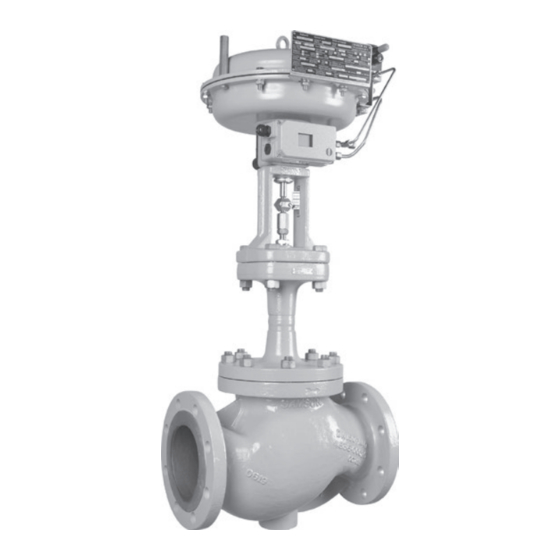
Design and principle of operation 3 Design and principle of oper- The signal pressure p is applied to the pilot valve whose coil is connected to the safety ation interlock circuit (switch 14, Fig. 3‑2 and See Fig. 3‑1 Fig. 3‑3). During operation, the coil is ener‑ gized and the signal pressure p acts on the The seat (4) and plug with plug stem (5) are... - Page 18 Body gasket Seat Bellows seal Plug (with plug stem) Plug stem with metal bellows Threaded bushing (packing nut) Test connection Stem connector nut Actuator stem Lock nut A26/27 Stem connector clamps Body nut Fig. 3-1: Type 3241-1-Gas Automatic Shut-off Valve EB 8020 EN...
- Page 19 Design and principle of operation Voltage Fig. 3-2: Functional diagram showing version without positioner Pilot valve Positioner Switch for safety interlock circuit Voltage P st Fig. 3-3: Functional diagram showing version with positioner EB 8020 EN...
-
Page 20: Versions
It prevents solid Depending on how the compression springs particles in the process medium from dam‑ are arranged in the SAMSON Type 3271 aging the valve. and Type 3277 Pneumatic Actuator, the valve has one of two different fail‑safe posi‑... -
Page 21: Valve Accessories
Information Sheet u T 8350 Leakage class according to DIN EN 161 Noise emissions 3.4 Technical data SAMSON is unable to make general state‑ The nameplates provide information on the ments about noise emissions. The noise emis‑ control valve version. See the 'Markings on sions depend on the valve version, plant fa‑... - Page 22 Design and principle of operation Table 3-1: Materials (material numbers according to DIN EN) Valve DN 15 to 150 DN 15 to 80 Strainer Forged stain‑ Cast steel Cast stainless Forged steel Cast steel Cast stainless Body less steel 1) 1.0619 steel 1.4408 1.0460 1.0619 steel 1.4408...
- Page 23 Design and principle of operation Table 3-2: Type 3241G Valve · Cast body: DN 15 to 150 · Forged body: DN 15 to 80 DIN DVGW test CE-0085CQ0516 mark Valve size Pressure rat‑ 0.4 1.6 0.4 1.6 6.3 6.3 16 6.3 16 25 40 25 40 60 80 63 100 160 160 260 coefficient (without flow 2.5 10 10...
- Page 24 Design and principle of operation Table 3-4: Pilot valves for Type 3241-1-Gas · Valid for closing time <5 s Valve Solenoid valve manufacturer and model number SAMSOMATIC model Norgren series Herion coefficient (Attachment: NAMUR (Attachment: threaded Valve size Actuator Fail-safe interface) connection) area [cm²]...
- Page 25 Design and principle of operation Dimensions and weights Table 3‑5 to Table 3‑7 provide a summary of the dimensions and weights of the standard version of Type 3241G Valve. Table 3-5: Dimensions for Type 3241G Valve Valve 1) 1) Length L Length L1 Height H1 with 175, 355 and 750 cm²...
- Page 26 Design and principle of operation Table 3-7: Weights Valve Weight without kg (approx.) actuator Strainer Weight kg (approx.) Actuator cm² 175v2 355v2 750v2 Weight of kg (approx.) Type 3271 Weight of kg (approx.) Type 3277 Solenoid valve kg (approx.) Dimensional drawings ØD ØD Type 3241‑1‑Gas Type 3241‑7‑Gas...
-
Page 27: Shipment And On-Site Transport
Shipment and on-site transport 4 Shipment and on-site trans- Î Leave the control valve in its transport container or on the pallet to transport it port on site. The work described in this section is only to Î Do not remove the protective caps from be performed by personnel qualified for the the inlet and outlet until immediately be‑... -
Page 28: Transporting The Valve
Î Observe the valve's center of gravity. Î Secure the valve against tipping over or A swivel hoist can be screwed into turning. SAMSON actuators with a female thread on the top diaphragm case in place of the eyebolt (see associated actuator WARNING documentation). -
Page 29: Lifting The Valve
Shipment and on-site transport 4.3.2 Lifting the valve − Do not damage the corrosion protection (paint, surface coatings). Repair any To install a large valve into the pipeline, use damage immediately. lifting equipment (e.g. crane or forklift) to lift − Protect the piping and any mounted valve accessories against damage. -
Page 30: Storing The Valve
At‑ Î Avoid long storage times. tach one sling to each flange of the body Î Contact SAMSON in case of different and to the rigging equipment of the storage conditions or long storage peri- crane or forklift (see Fig. 4‑1). - Page 31 Shipment and on-site transport − Do not damage the corrosion protection (paint, surface coatings). Repair any Our after-sales service can provide more de- damage immediately. tailed storage instructions on request. − Protect the control valve against moisture and dirt. Store it at a relative humidity of less than 75 %.
- Page 32 EB 8020 EN...
-
Page 33: Installation
To ensure that the valve functions properly, proceed as follows: 5.1 Installation conditions Î Observe the inlet and outlet lengths (see Table 5‑1). Contact SAMSON if the Work position valve conditions or states of the medium The work position for the control valve is the process deviate. -
Page 34: Preparation For Installation
− The valve is clean. Î Contact SAMSON if the mounting posi‑ − The valve and all valve accessories (in‑ tion is not as specified above. cluding piping) are not damaged. -
Page 35: Mounting The Valve
7. Attach a support or suspension on the leakage. valve, if necessary. Î Observe the specified tightening torques (u AB 0100). NOTICE Risk of valve damage due to the use of un- suitable tools. Î Only use tools approved by SAMSON (u AB 0100). EB 8020 EN... -
Page 36: Testing The Installed Valve
Installation 5.4 Testing the installed valve cessories not fitted with noise-reducing fit- tings. Both can damage hearing. Î Wear hearing protection when working DANGER near the valve. Risk of bursting due to incorrect opening of pressurized equipment or components. Valves and pipelines are pressure equipment WARNING WARNING that may burst when handled incorrectly. -
Page 37: Vent Holes
6. Depressurize the pipeline section and documentation). valve. 7. Rework any parts that leak and repeat SAMSON valves are delivered ready for the leak test. use. To test the valve functioning before start‑ up or putting back the valve into operation, Î... -
Page 38: Pressure Test
Installation Î Check whether the valve moves to the fail‑safe position (see the 'Design and principle of operation' section). 5.4.5 Pressure test The plant operator is responsible for per‑ forming the pressure test. Our after-sales service can support you to plan and perform a pressure test for your plant. -
Page 39: Start-Up
Start-up 6 Start-up Î Wear hearing protection when working near the valve. The work described in this section is only to be performed by personnel qualified for the assignment accordingly. WARNING WARNING Crush hazard arising from actuator and WARNING plug stem moving. Risk of burn injuries due to hot or cold com- Î... - Page 40 Start-up Before start‑up or putting the valve back into service, make sure the following conditions are met: − The valve is properly installed into the pipeline (see the 'Installation' section). − The leak and function tests have been completed successfully (see the 'Testing the installed valve' section).
-
Page 41: Operation
Operation 7 Operation WARNING WARNING Immediately after completing start‑up or put‑ Crush hazard arising from actuator and ting the valve back into operation (see the plug stem moving. 'Start‑up' section), the valve is ready for use. Î Do not insert hands or finger into the yoke while the air supply is connected to the actuator. - Page 42 EB 8020 EN...
-
Page 43: Malfunctions
Malfunctions 8 Malfunctions 8.1 Troubleshooting Malfunction Possible reasons Recommended action Actuator and plug stem Actuator is blocked. Check attachment. does not move on Unblock the actuator. demand. WARNING! A blocked actuator or plug stem (e.g. due to seizing up after remaining in the same position for a long time) can suddenly start to move uncontrollably. -
Page 44: Emergency Action
Malfunctions Malfunction Possible reasons Recommended action The valve leaks to the Defective packing Contact our after‑sales service. atmosphere (fugitive Defective bellows seal Contact our after‑sales service. emissions). Flange joint loose or Check the flange joint. gasket worn out Replace gasket at the flanged joint (see the 'Servicing' section) or contact our after‑sales service. -
Page 45: Servicing
Servicing 9 Servicing Î Allow components and pipelines to cool down or heat up. The work described in this section is only to Î Wear protective clothing and safety be performed by personnel qualified for the gloves. assignment accordingly. The following documents are also necessary WARNING for servicing the valve: Risk of personal injury due to pressurized... - Page 46 Risk of valve damage due to the use of un- springs. suitable tools. Actuators with preloaded springs are under Î Only use tools approved by SAMSON tension. They can be identified by the long (u AB 0100). bolts protruding from the bottom of the actu- ator.
-
Page 47: Periodic Testing
Servicing 9.1 Periodic testing Note The control valve was checked by SAMSON Depending on the operating conditions, before it left the factory. check the valve at certain intervals to prevent − Certain test results certified by SAMSON a possible failure before it can occur. Opera‑... - Page 48 Servicing Inspection and testing Corrective action Check the pipe connections and gaskets Check the bolted joint (tightening torque). on the valve and actuator for leakage. Put the control valve out of operation (see the 'Decommis‑ sioning' section). Replace the gasket on the flanged joint as described in section 9.4.
- Page 49 Threaded bushing (packing nut) Stem connector nut Lock nut P st Body nut Packing Body gasket Bellows seal Plug stem with bellows seal Test connection Strainer Actuator stem A26/27 Stem connector clamps Fig. 9-1: Type 3241-1-Gas Automatic Shut-off Valve EB 8020 EN...
-
Page 50: Preparing The Valve For Service Work
Servicing 9.2 Preparing the valve for 3. Test the valve (see Table 9‑1). The tests must be documented. service work 4. Put the control valve back into operation 1. Lay out the necessary material and tools (see the 'Start‑up' section). Make sure the to have them ready for the service work. - Page 51 Servicing Table 9-1: Required tests Seat leakage testing Standard IEC 60534‑4 or ANSI/FCI 70‑2 Test medium Use dry compressed air free of oil and grease Inlet: 4 bar (standard); max. 40 bar Test pressure Outlet: atmospheric pressure or connection to a flow meter 1. Move the plug out of the seat (valve closed). 2.
-
Page 52: Service Work
Servicing 9.4 Service work Aligning the V-port plug To achieve the best flow conditions inside the Î Before performing any service work, valve, the V‑port plug must always be in‑ preparations must be made to the control stalled with the port that releases the flow valve (see section 9.2). -
Page 53: Ordering Spare Parts And Operating Supplies
Servicing 9.5 Ordering spare parts and operating supplies Contact your nearest SAMSON subsidiary or SAMSON's After‑sales Service for infor‑ mation on spare parts, lubricants and tools. Spare parts See Annex for details on spare parts. Lubricant See document u AB 0100 for details on suitable lubricants. - Page 54 9-10 EB 8020 EN...
-
Page 55: Decommissioning
Decommissioning 10 Decommissioning WARNING The work described in this section is only to Risk of personal injury due to pressurized be performed by personnel qualified for the components and process medium escaping assignment accordingly. under pressure. Î Do not loosen the screw of the test con- nection while the valve is pressurized. - Page 56 Decommissioning (e.g. due to seizing up after remaining in 3. Disconnect and lock the pneumatic air the same position for a long time), re- supply to depressurize the actuator. lease any stored energy in the actuator 4. If necessary, allow the pipeline and valve (e.g.
-
Page 57: Removal
Removal 11 Removal WARNING WARNING The work described in this section is only to Risk of personal injury due to residual pro- be performed by personnel qualified for the cess medium in the valve. assignment accordingly. While working on the valve, residual process medium can escape and, depending on its properties, may lead to personal injury, e.g. -
Page 58: Removing The Actuator From The Valve
Removal 3. Remove the valve from the pipeline (see the 'Shipment and on‑site transport' sec‑ tion). 11.2 Removing the actuator from the valve See associated actuator documentation. 11-2 EB 8020 EN... -
Page 59: Repairs
Î Do not perform any repair work on your outside of your shipment so that the own. documents are clearly visible. Î Contact SAMSON's After-sales Service 4. Send the shipment to the address given for repair work. on the RMA. - Page 60 12-2 EB 8020 EN...
-
Page 61: Disposal
Disposal 13 Disposal Î Observe local, national and internation‑ al refuse regulations. Î Do not dispose of components, lubricants and hazardous substances together with your household waste. EB 8020 EN 13-1... - Page 62 13-2 EB 8020 EN...
-
Page 63: Certificates
Certificates 14 Certificates The following certificates are included on the next pages: − Declaration of conformity in compliance with Machinery Directive 2006/42/EC for Types 3241‑1 and 3241‑7 Control Valves on page 14‑2 − Declaration of incorporation in compliance with Machinery Directive 2006/42/EC for the Type 3241 Valve with other actuators other than Types 3271 and 3277 Actuators on page 14‑3... - Page 64 14-2 EB 8020 EN...
- Page 65 EB 8020 EN 14-3...
- Page 66 Frankfurt am Main, 06.07.2018 Dr. Michael Heß Klaus Hörschken Zentralabteilungsleiter Zentralabteilungsleiter Product Management & Technical Sales Entwicklung Ventile und Antriebe Revision 00 Classification: Public · SAMSON AKTIENGESELLSCHAFT · Weismüllerstraße 3 · 60314 Frankfurt am Main Seite 1 von 1 14-4 EB 8020 EN...
- Page 67 BNP Paribas N° compte 0002200215245 • Banque 3000401857 Tél.: +33 (0)4 72 04 75 00 • Fax: +33 (0)4 72 04 75 75 • E-mail: samson@samson.fr • Internet: www.samson.fr IBAN FR7630004018570002200215245 • BIC (code SWIFT) BNPAFRPPVBE Société par actions simpifiée au capital de 10 000 000 € • Siège social : Vaulx-en-Velin Crédit Lyonnais...
- Page 68 BNP Paribas N° compte 0002200215245 • Banque 3000401857 Tél.: +33 (0)4 72 04 75 00 • Fax: +33 (0)4 72 04 75 75 • E-mail: samson@samson.fr • Internet: www.samson.fr IBAN FR7630004018570002200215245 • BIC (code SWIFT) BNPAFRPPVBE Société par actions simpifiée au capital de 10 000 000 € • Siège social : Vaulx-en-Velin Crédit Lyonnais...
- Page 69 EB 8020 EN 14-7...
- Page 70 14-8 EB 8020 EN...
- Page 71 EB 8020 EN 14-9...
- Page 72 14-10 EB 8020 EN...
-
Page 73: Annex
Annex 15 Annex Valve nameplate Grooved pin 15.1 Tightening torques, lubri- Screw cants and tools Hanger u AB 0100 for tools, tightening torques and Travel indicator scale lubricants Protective cap Nameplate for gas version 15.2 Spare parts Plate with DVGW register number Body (valve) Body (strainer) Flange... - Page 74 Annex Note The exploded diagram shows a Type 3241G with a Type 3271 Pneumatic Actuator with 350 cm² actuator area. Contact our af- ter-sales service for other exploded dia- grams. 15-2 EB 8020 EN...
- Page 75 A20/22 A106 A100 A26/27 EB 8020 EN 15-3...
-
Page 76: After-Sales Service
You can reach our after‑sales service at aftersalesservice@samsongroup.com. Addresses of SAMSON AG and its subsid- iaries The addresses of SAMSON AG, its subsid‑ iaries, representatives and service facilities worldwide can be found on our website (www.samsongroup.com) or in all SAMSON product catalogs. - Page 80 EB 8020 EN SAMSON AKTIENGESELLSCHAFT Weismüllerstraße 3 · 60314 Frankfurt am Main, Germany Phone: +49 69 4009-0 · Fax: +49 69 4009-1507 samson@samsongroup.com · www.samsongroup.com...
Need help?
Do you have a question about the 3241-1-Gas and is the answer not in the manual?
Questions and answers