Table of Contents

Related Manuals for Samson 3246


Summary of Contents for Samson 3246
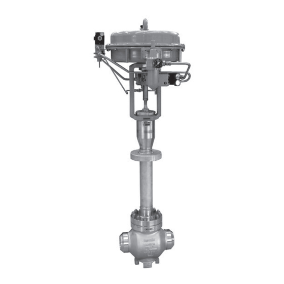
- Page 1 EB 8046 EN Translation of original instructions Type 3246 as globe and three-way valve Type 3246 Valve · ANSI and DIN versions In combination with an actuator, e.g. a Type 3271 or Type 3277 Pneumatic Actuator Edition February 2022...
- Page 2 Note on these mounting and operating instructions These mounting and operating instructions assist you in mounting and operating the device safely. The instructions are binding for handling SAMSON devices. The images shown in these instructions are for illustration purposes only. The actual product may vary.
-
Page 3: Table Of Contents
Contents Safety instructions and measures ..............1-1 Notes on possible severe personal injury ............1-4 Notes on possible personal injury ..............1-5 Notes on possible property damage .............1-7 Notes on the use of an RFID tag ..............1-8 Warnings on the device ................1-9 Markings on the device ................2-1 Valve nameplate ..................2-1 Actuator nameplate ..................2-2 Material identification number ..............2-2... - Page 4 Removal ....................11-1 11.1 Removing the valve from the pipeline ............11-2 11.2 Removing the actuator from the valve ............11-2 Repairs ....................12-1 12.1 Returning devices to SAMSON ..............12-1 Disposal ....................13-1 Certificates ....................14-1 Annex......................15-1 15.1 Tightening torques, lubricants and tools ............15-1 15.2 Spare parts ....................15-1 15.3...
-
Page 5: Safety Instructions And Measures
In case operators intend to use the control valve in other applica- tions or conditions than specified, contact SAMSON. SAMSON does not assume any liability for damage resulting from the failure to use the de- vice for its intended purpose or for damage caused by external forces or any other external factors. - Page 6 (see associated actuator documentation). When the valve is combined with a SAMSON Type 3271 or Type 3277 Pneumatic Actuator, the valve moves to a certain fail- safe position (see the 'Design and principle of operation' section) upon supply air or control signal failure.
- Page 7 Start-up and shutdown procedures fall within the scope of the operator's duties and, as such, are not part of these mounting and operating instructions. SAMSON is unable to make any statements about these procedures since the operative details (e.g. differential pressures and temperatures) vary in each individual case and are only known to the operator.
-
Page 8: Notes On Possible Severe Personal Injury
Safety instructions and measures − u AB 0100 for tools, tightening torques and lubricant − Manual u H 02: Appropriate Machinery Components for SAMSON Pneumatic Control Valves with a Declaration of Conformity of Final Machinery − For oxygen service: Manual u H 01 The packaging of valve constructed and sized for oxygen service has the following label... -
Page 9: Notes On Possible Personal Injury
All SAMSON staff receives appropriate training before performing any activities in connec- tion with oxygen service. SAMSON's After-sales Service also offers such training courses for service staff to allow them to learn how to handle devices for the above listed applications correctly and safely. - Page 10 Risk of personal injury due to preloaded springs. Valves in combination with pneumatic actuators with preloaded springs are under ten- sion. These control valves with SAMSON pneumatic actuators can be identified by the long bolts protruding from the bottom of the actuator.
-
Page 11: Notes On Possible Property Damage
Safety instructions and measures WARNING Risk of personal injury due to residual process medium in the valve. While working on the valve, residual medium can flow out of the valve and, depending on its properties, cause personal injury, e.g. (chemical) burns. Î... -
Page 12: Notes On The Use Of An Rfid Tag
Risk of valve damage due to the use of unsuitable tools. Certain tools are required to work on the valve. Î Only use tools approved by SAMSON (u AB 0100). Risk of valve damage due to the use of unsuitable lubricants. The lubricants to be used depend on the valve material. Unsuitable lubricants may cor- rode and damage surfaces. -
Page 13: Warnings On The Device
Safety instructions and measures 1.5 Warnings on the device Warning Meaning of the warning Location on the device Warning against moving parts There is a risk of injury to hands or fingers through the stroking movement of the actuator and plug stem if they are inserted into the yoke while the air supply is con- nected to the actuator. - Page 14 1-10 EB 8046 EN...
-
Page 15: Markings On The Device
Fig. 2-1 and the inscription table list all pos- 2.1 Valve nameplate sible characteristics and options that may appear on a valve nameplate. Only the in- scriptions relevant to the ordered Type 3246 Valve actually appear on the nameplate. Fig. 2-1: Inscriptions on the valve nameplate Item Inscription meaning... -
Page 16: Actuator Nameplate
Markings on the device 2.2 Actuator nameplate The nameplate is affixed to the intermediate piece or yoke of the valve (see Fig. 2-2). See associated actuator documentation. 2.3 Material identification number The seat and plug of the valves have an item number written on them. -
Page 17: Design And Principle Of Operation
The stem connector clamps connect To withstand low temperatures, the the actuator stem of the mounted actuator. Type 3246 Valve is always fitted with a long The plug stem or plug stem extension is insulating section (21). A circulation inhibitor... - Page 18 Design and principle of operation Fig. 3-1: Type 3246 Globe Valve with welding ends, Class 150 and 300/PN 16 and 40 Body Insulating section Intermediate piece Plug stem extension Seat Bolt Plug Threaded bushing (pack- Gasket (at the ing nut) intermediate piece) Stem connector nut...
- Page 19 Design and principle of operation Fig. 3-3: Type 3246 Globe Valve, Class 600 and 900/ PN 100 and 160 Body Yoke Seat Plug Threaded bushing (packing nut) Stem connector nut Lock nut Body nut Packing Body gasket Insulating section Circulation inhibitor Threaded bushing (circulation inhibitor)
-
Page 20: Fail-Safe Positions
Angle valve When the signal pressure is reduced or the air supply fails, the springs move the The Type 3246 Valve is also available as an actuator stem upwards and open the angle valve (special version) on request. valve. The valve closes when the signal pressure is increased enough to over- come the force exerted by the springs. -
Page 21: Additional Fittings
In these instructions, the preferable combina- tion with a SAMSON Type 3271 or Insulation Type 3277 Pneumatic Actuator is described. Control valves can be insulated to reduce The pneumatic actuator (with or without heat energy transfer. - Page 22 Type 3246 Valve. The lengths and heights in the dimensional Conformity drawings are shown on pages 3-10 and The Type 3246 Valve bears both the CE and 3-11. EAC marks of conformity. Temperature range The Type 3246 Valve is designed for a tem- perature range from –325 to +149 °F (–196...
- Page 23 Design and principle of operation Table 3-1: Dimensions of Type 3246 Globe Valve with welding ends · Class 150 and 300/ PN 16 and 40 ½ ¾ 1½ Valve size in 8.00 8.25 8.25 9.88 11.25 13.25 15.50 20.00 24.00 29.62 32.35 Length L Class 150...
- Page 24 Design and principle of operation Table 3-2: Dimensions of Type 3246 Globe Valve with welding ends · Class 600 and 900/ PN 100 and 160 ½ ¾ 1½ Valve size 8.00 8.25 8.25 9.88 11.25 13.25 15.50 20.00 24.00 Class 600/ PN 100 Length L 8.50...
- Page 25 33.66 39.29 6.30 9.06 5.98 7.99 10.0 Ød Cover plate 1.57 Table 3-4: Weights for Type 3246 ½ ¾ 1½ Valve size Globe valve, Class 150 and 300/PN 16 and 40 1202 1929 Weight, approx. Globe valve, Class 600 and 900/PN 100 and 160 1102 Class 600/...
- Page 26 Design and principle of operation Dimensional drawings Ød Ød Type 3246 · NPS ½ to 12 (DN 15 to 300), Type 3246 · NPS ½ to 8 (DN 15 to 200), Class 150 and 300 (PN 16 and 40) Class 600 and 900 (PN 100 and 160) 3-10 EB 8046 EN...
- Page 27 Design and principle of operation Dimensional drawing Ød Type 3246 as three-way valve · NPS ½ to 6 (DN 15 to 150), Class 150 and 300 (PN 16 and 40) Note The associated actuator documentation applies to actuators, e.g. SAMSON pneumatic actu- ators: u T 8310-1 for Type 3271 or Type 3277 Pneumatic Actuators up to 750 cm² actuator area u T 8310-2 for Type 3271 Actuator with 1000 cm²...
- Page 28 3-12 EB 8046 EN...
-
Page 29: Shipment And On-Site Transport
2. Check the shipment for transportation Î Stay clear of suspended or moving damage. Report any damage to loads. SAMSON and the forwarding agent Î Close off and secure the transport paths. (refer to delivery note). 3. Determine the weight and dimensions of... - Page 30 Risk of personal injury due to the control A swivel hoist can be screwed into valve tipping over. SAMSON actuators with a female thread on Î Observe the valve's center of gravity. the top diaphragm case in place of the Î...
-
Page 31: Transporting The Valve
Shipment and on-site transport 4.3.1 Transporting the valve ping off the hook during lifting and transporting. The control valve can be transported using − Secure slings against slipping. lifting equipment (e.g. crane or forklift). − Make sure the slings can be removed Î... - Page 32 Shipment and on-site transport 3. Carefully lift the control valve. Check whether the lifting equipment and acces- sories can bear the weight. 4. Move the control valve at an even pace to the site of installation. 5. Install the valve into the pipeline (see the 'Installation' section).
- Page 33 Shipment and on-site transport Fig. 4-1: Lifting points on the control valve: with flanges and insulating section (left) · With welding ends and insulating section (right) EB 8046 EN...
-
Page 34: Storing The Valve
Elastomer, e.g. actuator diaphragm Î Avoid long storage times. − To keep elastomers in shape and to pre- Î Contact SAMSON in case of different vent cracking, do not bend them or hang storage conditions or longer storage them up. -
Page 35: Installation
The work position for the control valve is the ommendations. Contact SAMSON if the front view looking onto the operating con- trols (including valve accessories). Table 5-1: Inlet and outlet lengths... -
Page 36: Preparation For Installation
Î Observe the recommended inlet and make sure that they are easily accessible outlet lengths (see Table 5-1). Contact and can be operated safely from the SAMSON if the valve conditions or states work position. of the medium process deviate. Vent plugs Î... -
Page 37: Mounting The Device
NOTICE work. Risk of valve damage due to the use of Î Flush the pipelines. unsuitable tools. Î Only use tools approved by SAMSON Note (u AB 0100). The plant operator is responsible for clean- ing the pipelines in the plant. 5.3.1... - Page 38 Installation Actuator, observe the mounting and operat- NOTICE ing instructions of the hand-operated actua- Impaired functioning due to incorrectly tor (handwheel) to mount the anti-rotation applied lubricant. fixture u EB 8312-X. Î Do not apply any lubricant to the threads of the clamps (301) or the plug stem. a) Standard version for Series 240 Valves in valve 8.
- Page 39 Installation 14. Extend the actuator stem again and mount the stem connector clamps. Plug stem Legend Yoke Screws Hanger Travel indicator scale Screws Castellated nut Warning label Ball bearing Fig. 5-1: Overview of yoke assembly with travel indicator scale in the standard version EB 8046 EN...
- Page 40 Installation Plug stem Legend Stem Lubricant Gleitmo 1763 V Clamps Screws Washers Sliding washers Fig. 5-2: Overview of anti-rotation fixture assembly in the standard version EB 8046 EN...
- Page 41 Installation b) Special version for 8. Thread the stem (9) upwards until the head of the stem rests on the extended Series 250 Valves, DN 50 to actuator stem. 100/NPS 2 to 4 9. Retract the actuator stem to relieve the stem (9). See Fig. 5-3 and Fig. 5-4 10.
- Page 42 Installation Legend Yoke Screws Hanger Plug stem Travel indicator scale Castellated nut Warning label Holder Screws Washers Fig. 5-3: Overview of yoke assembly with travel indicator scale in the special version EB 8046 EN...
- Page 43 Installation Plug stem Legend Stem Lubricant Gleitmo 1763 V Clamps Screws Washers Sliding washers Fig. 5-4: Overview of anti-rotation fixture assembly in the special version EB 8046 EN...
- Page 44 Installation Table 5-4: Mounting dimensions for Types 3271 and 3277 Pneumatic Actuators · See Fig. 5-5 for dimensional drawing Trav- Actuator Actuator preloading Dimension when the valve is closed [mm] [cm²] [mm] [mm] DN 50 to 100/NPS 2 to 4 · Special version 3.75 –...
- Page 45 Installation Trav- Actuator Actuator preloading Dimension when the valve is closed [mm] [cm²] [mm] [mm] DN 200 to 250/NPS 8 to 10 up to seat bore 200 · Standard version 1000 1400-60 87.5 1400-120 2800 5600 DN 250/NPS 10, seat bore 250 and DN 300 to 500/NPS 12 to 20 · Standard version 1000 1400-60 1400-120...
- Page 46 Installation Ball bearings (standard version only) Fig. 5-5: Dimensional drawing with mounting dimensions for Types 3271 and 3277 Pneumatic Actuators 5-12 EB 8046 EN...
-
Page 47: Mounting The Actuator Onto The Valve
Installation 5.3.2 Mounting the actuator Depending on the version, SAMSON control valves are either delivered with the actuator onto the valve already mounted on the valve or the valve and actuator are delivered separately. When WARNING delivered separately, the valve and actuator Risk of personal injury due to preloaded must be assembled together on site. - Page 48 Installation Versions with perforated plug Only one hole is located near the seal facing of perforated plugs with equal percentage characteristic. Depending on the valve size, the hole pattern varies and is partly unsym- Plug metrical. The process medium in the valve stem flows through the holes as soon as the plug is lifted out of the seat.
-
Page 49: Installing The Valve Into The Pipeline
Installation 2. Loosen the screws on the travel indicator 3. Remove the protective caps from the scale. valve ports before installing the valve. 3. Align the travel indicator scale. 4. Lift the valve using suitable lifting equip- ment to the site of installation (see infor- 4. - Page 50 Installation process medium under pressure can cause Î Before unblocking the actuator and plug serious injury or even death. stem after they have become blocked Before working on the control valve: (e.g. due to seizing up after remaining in Î Depressurize all plant sections affected the same position for a long time), re- and the valve (including the actuator).
-
Page 51: Leak Test
Installation 5. Check the valve for leakage to the atmo- WARNING sphere. Risk of personal injury due to preloaded 6. Depressurize the pipeline section and springs. valve. Actuators with preloaded springs are under 7. Rework any parts that leak and repeat tension. - Page 52 Installation − Retract the plug stem to open the valve. − Observe the maximum permissible pres- sure for both the valve and plant. 5-18 EB 8046 EN...
-
Page 53: Start-Up
Start-up 6 Start-up Î Before working on the control valve, disconnect and lock the pneumatic air The work described in this section is only to supply as well as the control signal. be performed by personnel appropriately Î Do not impede the movement of the actu- qualified to carry out such tasks. - Page 54 Start-up 'Intended use' in the 'Safety instructions and measures' section). Start-up/putting the valve back into opera- tion 1. Allow the valve to cool down or warm up to reach ambient temperature before start-up when the ambient temperature and process medium temperature differ greatly or the medium properties require such a measure.
-
Page 55: Operation
Operation 7 Operation Î Before working on the control valve, disconnect and lock the pneumatic air Immediately after completing start-up or put- supply as well as the control signal. ting the valve back into operation, the valve Î Do not impede the movement of the is ready for use. -
Page 56: Normal Operation
Operation 7.1 Normal operation The handwheel of valves with actuators fitted with a handwheel must be in the neutral po- sition during normal operation. 7.2 Manual operation Valves with actuators fitted with a handwheel can be manually closed or opened in case of supply air failure. -
Page 57: Malfunctions
Malfunctions 8 Malfunctions Read hazard statements, warnings and caution notes in the 'Safety instructions and mea- sures' section. 8.1 Troubleshooting Malfunction Possible reasons Recommended action Actuator and plug stem Actuator is blocked. Check attachment. does not move on de- Remove the blockage. mand. -
Page 58: Emergency Action
Malfunctions Malfunction Possible reasons Recommended action The valve leaks to the Defective packing Replace packing (see the 'Servicing' section) or con- atmosphere (fugitive tact our after-sales service. emissions). Flange joint loose or Check the flange joint. gasket worn out Replace gasket at the flanged joint (see the 'Servic- ing' section) or contact our after-sales service. -
Page 59: Servicing
Servicing 9 Servicing Î Allow components and pipelines to reach ambient temperature. The work described in this section is only to Î Wear protective clothing and safety be performed by personnel appropriately gloves. qualified to carry out such tasks. The following documents are also required WARNING for servicing the valve: Risk of hearing loss or deafness due to loud... - Page 60 NOTICE Risk of valve damage due to the use of un- suitable tools. WARNING Î Only use tools approved by SAMSON Risk of personal injury due to preloaded (u AB 0100). springs. Actuators with preloaded springs are under tension.
-
Page 61: Periodic Testing
Servicing 9.1 Periodic testing − Only use original spare parts by SAMSON, which comply with the original Depending on the operating conditions, specifications. check the valve at certain intervals to prevent possible failure before it can occur. Plant op- erators are responsible for drawing up an inspection and test plan. -
Page 62: Preparing The Valve For Service Work
Servicing Inspection and testing Action to be taken in the event of a negative result: Check to ensure that the actuator and Unblock a blocked actuator and plug stem. plug stem move smoothly. WARNING! A blocked actuator or plug stem (e.g. due to seizing up after remaining in the same position for a long time) can suddenly start to move uncontrollably. -
Page 63: Installing The Valve After Service Work
Servicing 9.3 Installing the valve after − Replacing the seat and plug -> ‘Globe valve, Class 600 and 900/ service work PN 100 and 160’ 1. Mount actuator. See associated actuator The actuator can remain mounted on the documentation and the 'Installation' sec- valve for the following service work. - Page 64 Servicing Fig. 9-1: Type 3246 Globe valve · Class 150 and 300/PN 16 and 40 (left) · Class 600 and 900/ PN 100 and 160 (right) EB 8046 EN...
- Page 65 Servicing − For Class 150 and 300/PN 16 and Class 600 and 900/PN 100 and 160: 40: The valve size is place the insulating section (21) together ≤NPS 6/≤DN 150. with the yoke (3) and plug (5) onto the − For Class 600 and 900/PN 100 and body (1). 160: The valve size is The following points must be observed: ≤NPS 4/≤DN 100.
-
Page 66: Replacing The Circulation Inhibitor
Servicing 9.4.2 Replacing the circulation 1. Undo the body nuts (14) gradually in a crisscross pattern. inhibitor 2. Lift the insulating section (21) together with the intermediate piece (2), plug (5) a) Globe and three-way valve, and plug stem extension (25) off the Class 150 and 300/PN 16 body (1). - Page 67 Servicing 6. Carefully pull all the individual parts of V-shaped port of the V-port plug faces the circulation inhibitor out of the pack- toward the valve outlet. ing chamber using a suitable tool. Versions with perforated plug: align the plug (5), making sure that the hole clos- 7.
- Page 68 Servicing 4. Lift the insulating section (21) together 14. Lightly screw in the threaded bushing with the plug stem and plug (5) off the (87), but do not tighten it yet. body (1). 15. Slide the plug with plug stem (5) into the 5.
-
Page 69: Replacing The Packing
Servicing 9.4.3 Replacing the packing a) Globe and three-way valve, Class 150 and 300/PN 16 and 40 NOTICE Risk of control valve damage due to 1. Unscrew the stem connector nut (9) and incorrect servicing. lock nut (10) from the plug stem exten- Î... - Page 70 Servicing 7. Remove the gasket (39). Carefully clean 4. Pull the entire packing out of the packing the sealing faces in the intermediate chamber using a suitable tool. piece (2) and on the insulating section 5. Renew the damaged parts and carefully (21).
-
Page 71: Replacing The Seat And Plug
Servicing 9.4.4 Replacing the seat and 2. Lift the insulating section (21) together with the plug stem extension (25), plug plug stem and plug (5) off the body (1). 3. Replace the gasket (see section 9.4.1) NOTICE NOTICE 4. Undo the grub screw (88) at the bottom Risk of damage to the facing of the seat threaded bushing (87) using a hex sock- and plug due to incorrect servicing. - Page 72 Servicing b) Globe valve, Class 600 and 13. Screw the new plug and plug stem (5) onto the plug stem extension (25) using a 900/PN 100 and 160 suitable tool. Observe tightening torques. 14. Tighten the bottom threaded bushing NOTICE (87). Observe tightening torques. Risk of control valve damage due to incor- 15.
- Page 73 Servicing Version with V-port plug: align the plug Note (5), making sure that the largest Do not completely unscrew the grub screw. V-shaped port of the V-port plug faces toward the valve outlet. 9. Loosen threaded bushing (87). Versions with perforated plug: align the plug (5), making sure that the hole clos- Note est to the seal facing of the plug faces to-...
-
Page 74: Ordering Spare Parts And Operating Supplies
Servicing 9.5 Ordering spare parts and operating supplies Contact your nearest SAMSON subsidiary or SAMSON's After-sales Service for infor- mation on spare parts, lubricants and tools. Spare parts See Annex for details on spare parts. Lubricant See document u AB 0100 for details on suitable lubricants. -
Page 75: Decommissioning
Decommissioning 10 Decommissioning WARNING The work described in this section is only to Risk of hearing loss or deafness due to loud be performed by personnel appropriately noise. qualified to carry out such tasks. Noise emission (e.g. cavitation or flashing) may occur during operation caused by the process medium and the operating DANGER... - Page 76 Decommissioning 5. If necessary, allow the pipeline and valve WARNING WARNING components to cool down or warm up to Risk of personal injury due to exhaust air the ambient temperature. being vented. While the valve is operating, air is vented from the actuator, for example, during closed-loop operation or when the valve opens or closes.
-
Page 77: Removal
Removal 11 Removal WARNING WARNING The work described in this section is only to Risk of personal injury due to residual be performed by personnel appropriately process medium in the valve. qualified to carry out such tasks. While working on the valve, residual me- dium can flow out of the valve and, depend- ing on its properties, cause personal injury, WARNING... -
Page 78: Removing The Valve From The Pipeline
Removal actuator springs is transmitted to the 3. Remove the valve from the pipeline (see actuator stem and the stem (9). the 'Shipment and on-site transport' sec- Î First remove the actuator from the valve tion). or ensure it cannot transmit any forces to 11.2 Removing the actuator the actuator stem before removing the anti-rotation fixture on the plug stem. -
Page 79: Repairs
Î Do not perform any repair work on your outside of your shipment so that the own. documents are clearly visible. Î Contact SAMSON's After-sales Service 4. Send the shipment to the address given for repair work. on the RMA. - Page 80 12-2 EB 8046 EN...
-
Page 81: Disposal
Disposal 13 Disposal Î Observe local, national and internation- al refuse regulations. Î Do not dispose of components, lubricants and hazardous substances together with your household waste. EB 8046 EN 13-1... - Page 82 13-2 EB 8046 EN...
-
Page 83: Certificates
− Country of origin: France, see page 14-3 to 14-4 − Declaration of conformity in compliance with Machinery Directive 2006/42/EC for Types 3246-1 and 3246-7 Control Valves on page 14-5 − Declaration of incorporation in compli- ance with Machinery Directive 2006/42/EC for the Type 3246 Valve with other actuators other than Types 3271 and 3277 Actuators on... - Page 84 14-2 EB 8046 EN...
- Page 85 Module H / Modul H, N°/ Nr CE-0062-PED-H-SAM 001-20-FRA-rev-A 2021-06 Par la présente, SAMSON REGULATION SAS déclare sous sa seule responsabilité pour les produits suivants : For the following products, SAMSON REGULATION SAS hereby declares under its sole responsibility: SAMSON REGULATION SAS erklärt in alleiniger Verantwortung für folgende Produkte: Appareils / Devices / Geräte...
- Page 86 Das Qualitätssicherungssystem des Herstellers wird von folgender benannter Stelle überwacht: Bureau Veritas Services SAS N°/Nr 0062, 8 Cours du Triangle, 92800 PUTEAUX - LA DEFENSE Fabricant / manufacturer / Hersteller : Samson Régulation SAS, 1, rue Jean Corona, FR-69120 VAULX-EN-VELIN Vaulx-en-Velin, le 11/06/21 Bruno Soulas Joséphine Signoles-Fontaine...
- Page 87 EB 8046 EN 14-5...
- Page 88 14-6 EB 8046 EN...
-
Page 89: Annex
Annex 15 Annex 15.1 Tightening torques, lubricants and tools u AB 0100 for tools, tightening torques and lubricants 15.2 Spare parts 1 Body 80 Nameplate 2 Intermediate piece 81 Grooved pin 3 Yoke 82 Screw 4 Seat 83 Hanger 1) 5 Plug (with plug stem) 84 Travel indicator scale 8 Threaded bushing (packing nut) 85 Screw... - Page 90 15-2 EB 8046 EN...
- Page 91 EB 8046 EN 15-3...
-
Page 92: After-Sales Service
You can reach our after-sales service at aftersalesservice@samsongroup.com. Addresses of SAMSON AG and its subsid- iaries The addresses of SAMSON AG, its subsid- iaries, representatives and service facilities worldwide can be found on our website (www.samsongroup.com) or in all SAMSON product catalogs. - Page 96 EB 8046 EN SAMSON AKTIENGESELLSCHAFT Weismüllerstraße 3 · 60314 Frankfurt am Main, Germany Phone: +49 69 4009-0 · Fax: +49 69 4009-1507 samson@samsongroup.com · www.samsongroup.com...
Need help?
Do you have a question about the 3246 and is the answer not in the manual?
Questions and answers