
Related Manuals for Samson 3248


Summary of Contents for Samson 3248
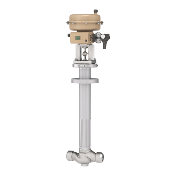
- Page 1 EB 8093-1 EN Translation of original instructions Type 3248 Valve · ANSI version In combination with an actuator, e.g. a Type 3271 or Type 3277 Pneumatic Actuator Edition November 2020...
- Page 2 Note on these mounting and operating instructions These mounting and operating instructions assist you in mounting and operating the device safely. The instructions are binding for handling SAMSON devices. The images shown in these instructions are for illustration purposes only. The actual product may vary.
-
Page 3: Table Of Contents
Contents Safety instructions and measures ..............1-1 Notes on possible severe personal injury ............1-5 Notes on possible personal injury ..............1-6 Notes on possible property damage .............1-7 Warnings on the device ................1-9 Markings on the device ................2-1 Valve nameplate ..................2-1 Actuator nameplate ..................2-2 Material identification number ..............2-2 Design and principle of operation ...............3-1 Fail-safe positions ..................3-4... - Page 4 Removal ....................11-1 11.1 Removing the valve from the pipeline ............11-1 11.2 Removing the actuator from the valve ............11-2 Repairs ....................12-1 12.1 Returning devices to SAMSON ..............12-1 Disposal ....................13-1 Certificates ....................14-1 Annex......................15-1 15.1 Tightening torques, lubricants and tools ............15-1 15.2 Spare parts ....................15-1 15.3...
-
Page 5: Safety Instructions And Measures
In case operators intend to use the control valve in other applications or conditions than specified, contact SAMSON. SAMSON does not assume any liability for damage resulting from the failure to use the de- vice for its intended purpose or for damage caused by external forces or any other external factors. - Page 6 (see associated actuator documentation). When the valve is combined with a SAMSON Type 3271 or Type 3277 Pneumatic Actuator, the valve moves to a certain fail- safe position (see the 'Design and principle of operation' section) upon supply air or control signal failure.
- Page 7 Start-up and shutdown procedures fall within the scope of the operator's duties and, as such, are not part of these mounting and operating instructions. SAMSON is unable to make any statements about these procedures since the operative details (e.g. differential pressures and temperatures) vary in each individual case and are only known to the operator.
- Page 8 − Mounting and operating instructions for mounted valve accessories (positioner, solenoid valve etc.) − u AB 0100 for tools, tightening torques and lubricant − For oxygen service: Manual u H 01 − Manual u H 02: Appropriate Machinery Components for SAMSON Pneumatic Control Valves with a Declaration of Conformity of Final Machinery EB 8093-1 EN...
-
Page 9: Notes On Possible Severe Personal Injury
Risk of injury due to incorrect handling of oxygen or cryogenic gases in applica- tions. The Type 3248 Valve is frequently used for oxygen service or applications with cryo- genic gases. Oxygen is a hazardous substance, which reacts quickly, leading to com- bustion and explosions. -
Page 10: Notes On Possible Personal Injury
Safety instructions and measures 1.2 Notes on possible personal injury WARNING Risk of burn injuries due to cold components and pipelines. Depending on the process medium, valve components and pipelines may get extremely cold and cause cryogenic burns. Î Allow components and pipelines to reach ambient temperature. Î... - Page 11 Risk of personal injury due to preloaded springs. Valves in combination with pneumatic actuators with preloaded springs are under ten- sion. These control valves with SAMSON pneumatic actuators can be identified by the long bolts protruding from the bottom of the actuator.
-
Page 12: Notes On Possible Property Damage
Risk of valve damage due to the use of unsuitable tools. Certain tools are required to work on the valve. Î Only use tools approved by SAMSON (u AB 0100). Risk of valve damage due to the use of unsuitable lubricants. The lubricants to be used depend on the valve material. Unsuitable lubricants may cor- rode and damage surfaces. -
Page 13: Warnings On The Device
Safety instructions and measures 1.4 Warnings on the device Warning Meaning of the warning Location on the device Warning against moving parts There is a risk of injury to hands or fingers through the stroking movement of the actuator and plug stem if they are inserted into the yoke while the air supply is con- nected to the actuator. - Page 14 1-10 EB 8093-1 EN...
-
Page 15: Markings On The Device
2.1 Valve nameplate possible characteristics and options that may appear on a valve nameplate. Only the inscriptions relevant to the ordered Type 3248 Valve actually appear on the nameplate. Fig. 2-1: Inscriptions on the valve nameplate Item Inscription meaning Item Inscription meaning... -
Page 16: Actuator Nameplate
Markings on the device 2.3 Material identification The nameplate is affixed to the valve bonnet (see Fig. 2-2). number The seat and plug of the valves have an item number written on them. You can contact us stating this item number to find out which material is used. -
Page 17: Design And Principle Of Operation
(2) is designed as a yoke (see ation Fig. 3-1). In the Class 600 version, the valve bonnet (2) is designed as an intermediate The Type 3248 is available in the following versions: piece. A yoke (3) is fastened onto the valve bonnet with a castellated nut (92) (see −... - Page 18 Bonnet gasket A26/27 Plug stem with metal bellows Bellows nut Test connection Spacer stem Actuator stem A26/27 Stem connector clamps Cover plate Fig. 3-1: Type 3248 Globe Valve with stainless steel body (Class 150 to 300) · With Type 3271 Pneumatic Actuator EB 8093-1 EN...
- Page 19 Plug (with plug stem) Threaded bushing (packing nut) Stem connector nut Lock nut Packing Bonnet gasket Bolt Plug stem with metal bellows Bellows nut Test connection Spacer stem Castellated nut Fig. 3-2: Type 3248 Angle Valve with stainless steel body, Class 600 EB 8093-1 EN...
-
Page 20: Fail-Safe Positions
− Actuator stem extends (FA) Larger valve sizes When the signal pressure is reduced or The Type 3248 Valve is available up to valve the air supply fails, the springs move the size NPS 8. actuator stem downward and close the valve. -
Page 21: Additional Fittings
Conformity Refer to the instructions in the 'Installation' section. The Type 3248 Valve bears both the CE and EAC marks of conformity. Test connection The test connection at the valve bonnet can be used to monitor the sealing ability of the bellows. - Page 22 Dimensions and weights Table 3-1 to Table 3-6 provide an overview of the dimensions of the various versions of Type 3248 Valve. Table 3-7 lists the weights of the various versions of Type 3248 Valve. The lengths and heights in the dimensional drawings are shown on pages 3-10 and...
- Page 23 Design and principle of operation Table 3-1: Dimensions of globe valve with stainless steel body, short pattern, Class 150 to 300, without cover plate (Fig. 3-3) Valve 1½ Socket weld ends Butt weld ends (Schedule 10s) 7.75 9.25 10.50 12.50 14.50 17.75 29.75 29.90 29.90...
- Page 24 Design and principle of operation Valve 1½ Socket weld ends Butt weld ends (Schedule 10s) 21.0 21.0 21.0 21.0 22.0 27.0 3.15 3.94 3.94 – – – – – – 41.34 35.43 35.43 35.43 43.31 43.31 1050 1100 1100 9.84 10.63 10.63 14.57...
- Page 25 Design and principle of operation Table 3-4: Dimensions of globe valve with stainless steel body, long pattern, Class 600, with cover plate (Fig. 3-4) Valve 1½ Socket weld ends Butt weld ends (Schedule 10s) 8.25 9.88 11.25 13.25 15.50 20.0 32.36 32.17 32.17 32.76 38.74...
- Page 26 Design and principle of operation (X 1:2) (X 1:2) Fig. 3-3: Globe valve (without cover plate) Fig. 3-4: Globe valve (with cover plate) * Dimension H6 only in Class 150 to 300 and NPS 1 to 2 Table 3-5: Dimensions of angle valve with stainless steel body, Class 300 (Fig. 3-5) Valve 1½...
- Page 27 SCH 40S pipe connection Note Refer to the following data sheets for dimensions and weights of the SAMSON pneumatic actuators: u T 8310-1 for Type 3271 or Type 3277 Pneumatic Actuators up to 750 cm² actuator area u T 8310-2 for Type 3271 Actuator with 1000 cm² actuator area and larger u T 8310-3 for Type 3271 Actuator with 1400-60 cm²...
- Page 28 Design and principle of operation Fig. 3-5: Angle valve Ød Table 3-7: Weights of Type 3248 Valve without actuator Valve 1½ Globe valve with stainless steel body, short and long pattern, Class 150 to 300 Weight Globe valve with stainless steel body, long pattern, Class 600 Weight Angle valve with stainless steel body, Class 300...
-
Page 29: Shipment And On-Site Transport
2. Check the shipment for transportation Î Stay clear of suspended or moving damage. Report any damage to loads. SAMSON and the forwarding agent Î Close off and secure the transport paths. (refer to delivery note). 3. Determine the weight and dimensions of... -
Page 30: Transporting The Valve
Risk of personal injury due to the control A swivel hoist can be screwed into valve tipping over. SAMSON actuators with a female thread on Î Observe the valve's center of gravity. the top diaphragm case in place of the Î... -
Page 31: Lifting The Valve
Shipment and on-site transport a) Lifting with the actuator − Protect the piping and any mounted valve accessories against damage. mounted − Protect the control valve against moisture and dirt. The control valve can be lifted in the hori- zontal position either using one hook −... - Page 32 Shipment and on-site transport Fig. 4-1: Lifting points on the control valve: lifting in the horizontal position using one hook Fig. 4-2: Lifting points on the control valve: lifting in the horizontal position using a beam EB 8093-1 EN...
- Page 33 Shipment and on-site transport b) Lifting with the protective cover mounted 1. Attach two slings to the cryogenic exten- sion bonnet and to the rigging equip- ment (e.g. hook) of the crane or forklift (see Fig. 4-3). 2. NPS 4 and larger: attach additional sling to support the valve at the body.
- Page 34 Shipment and on-site transport c) Lifting the control valve with 4. Carefully lift the control valve. Check whether the lifting equipment and acces- mounted actuator in the up- sories can bear the weight. right position 5. Move the control valve at an even pace to the site of installation.
- Page 35 Shipment and on-site transport Fig. 4-4: Lifting points on the control valve: Fig. 4-5: Lifting points on the control valve: lifting of a globe valve in the upright lifting of an angle valve in the upright position position EB 8093-1 EN...
-
Page 36: Storing The Valve
Elastomer, e.g. actuator diaphragm Î Avoid long storage times. − To keep elastomers in shape and to pre- Î Contact SAMSON in case of different vent cracking, do not bend them or hang storage conditions or longer storage them up. -
Page 37: Installation
5.1 Installation conditions vary depending on several variables and process conditions and are intended as Work position recommendations. Contact SAMSON if the lengths are significantly shorter than the The work position for the control valve is the recommended lengths. front view looking onto the operating con- trols (including valve accessories). -
Page 38: Preparation For Installation
Î Observe the recommended inlet and Î Avoid supporting or suspending in the outlet lengths (see Table 5-1). Contact area around bellows nut (41). SAMSON if the valve conditions or states Valve accessories of the medium process deviate. Î During connection of valve accessories, Î... -
Page 39: Mounting The Device
NOTICE work. Risk of valve damage due to the use of Î Flush the pipelines. unsuitable tools. Î Only use tools approved by SAMSON Note (u AB 0100). The plant operator is responsible for clean- ing the pipelines in the plant. Î For steam applications, dry the pipelines. -
Page 40: Installing The Valve Into The Pipeline
Installation 5.3.1 Installing the valve into valve. The arrow on the valve indicates the direction of flow. the pipeline 5. Completely retract the actuator stem to protect the plug from sparks during weld- NOTICE ing. Risk of valve damage due to work being With mounted protective cover: turn the carried out by personnel not qualified for adjustment bolt (95.2) clockwise. - Page 41 Installation with bellows seal (37) is completely screwed 2. Carefully place the valve bonnet (2) to- into the adjustment bolt (95.2). gether with the spacer stem (71) on the valve body (1). Place the spacer stem Moving the plug stem over the thread of the plug stem (37) and Î...
- Page 42 Installation 95.3 Class 150 to 300 95.4 95.9 95.1 95.6 95.5 95.7 95.2 Body 95.1 Cover of protective cover Valve bonnet 95.2 Stud/adjustment bolt Yoke 95.3 Axial retaining ring Stem connector nut 95.4 O-ring Lock nut 95.5 Gasket Bonnet gasket 95.6 Screw plug (test Bolt connection) 95.7 O-ring (glued)
-
Page 43: Mounting The Actuator Onto The Valve
(see associated actuator documentation). 1x large V-port: Depending on the version, SAMSON control First to release the flow when the valves are either delivered with the actuator plug is lifted out of the seat. -
Page 44: Testing The Installed Valve
Installation 5.4 Testing the installed valve seal facing and is uncovered first when the plug is lifted out of the seat. Î On mounting the actuator, make sure DANGER that the hole uncovered first faces toward Risk of bursting due to incorrect opening of the valve outlet: pressurized equipment or components. -
Page 45: Leak Test
Installation cessories not fitted with noise-reducing fit- WARNING tings. Both can damage hearing. Risk of personal injury due to preloaded Î Wear hearing protection when working springs. near the valve. Actuators with preloaded springs are under tension. They can be identified by the long bolts protruding from the bottom of the actu- WARNING WARNING... -
Page 46: Travel Motion
Installation 5. Check the valve for leakage to the atmo- − Observe the maximum permissible pres- sphere. sure for both the valve and plant. 6. Depressurize the pipeline section and Pressure test with mounted actuator valve. 1. Retract the plug stem to open the valve. 7. -
Page 47: Start-Up
Start-up 6 Start-up WARNING WARNING The work described in this section is only to Crush hazard arising from actuator and be performed by personnel appropriately plug stem moving. qualified to carry out such tasks. Î Do not insert hands or finger into the yoke while the air supply is connected to the actuator. - Page 48 Start-up − The leak and function tests have been completed successfully (see 'Testing the installed valve' in the 'Installation' sec- tion). − The prevailing conditions in the plant section concerned meet the valve sizing requirements (see information under 'In- tended use' in the 'Safety instructions and measures' section).
-
Page 49: Operation
Operation 7 Operation WARNING WARNING Immediately after completing start-up or put- Crush hazard arising from actuator and ting the valve back into operation, the valve plug stem moving. is ready for use. Î Do not insert hands or finger into the yoke while the air supply is connected to the actuator. -
Page 50: Normal Operation
Operation 7.1 Normal operation The handwheel of valves with actuators fitted with a handwheel must be in the neutral po- sition during normal operation. 7.2 Manual operation Valves with actuators fitted with a handwheel can be manually closed or opened in case of supply air failure. -
Page 51: Malfunctions
Malfunctions 8 Malfunctions Read hazard statements, warnings and caution notes in the 'Safety instructions and mea- sures' section. 8.1 Troubleshooting Malfunction Possible reasons Recommended action Actuator and plug stem Actuator is blocked. Check attachment. does not move on de- Remove the blockage. mand. -
Page 52: Emergency Action
Malfunctions Malfunction Possible reasons Recommended action The valve leaks to the Defective packing Contact our after-sales service. atmosphere (fugitive Defective bellows seal Contact our after-sales service. emissions). Flange joint loose or Check the flange joint. gasket worn out Replace gasket at the flanged joint (see the 'Servic- ing' section) or contact our after-sales service. -
Page 53: Servicing
Servicing 9 Servicing Î Allow components and pipelines to reach ambient temperature. The work described in this section is only to Î Wear protective clothing and safety be performed by personnel appropriately gloves. qualified to carry out such tasks. The following documents are also necessary WARNING for servicing the valve: Risk of personal injury due to pressurized... - Page 54 Risk of valve damage due to the use of Actuators with preloaded springs are under unsuitable tools. tension. They can be identified by the long Î Only use tools approved by SAMSON bolts protruding from the bottom of the actu- (u AB 0100). ator.
-
Page 55: Periodic Testing
Servicing 9.1 Periodic testing Note The control valve was checked by SAMSON Depending on the operating conditions, before it left the factory. check the valve at certain intervals to prevent − Certain test results certified by SAMSON a possible failure before it can occur. Plant... - Page 56 Servicing Inspection and testing Action to be taken in the event of a negative result: Check the valve for external damage Remove any damage immediately. If necessary, put the (e.g. corrosion). control valve out of operation (see the 'Decommissioning' section). Check the valve accessories to ensure Tighten the connections of the valve accessories.
-
Page 57: Preparing The Valve For Service Work
Servicing 9.2 Preparing the valve for 9.3 Mounting the valve after service work service work 1. Lay out the necessary material and tools 1. Mount actuator. See associated actuator to have them ready for the service work. documentation and in the 'Installation' section. -
Page 58: Replacing The Gasket
Servicing 9.4.1 Replacing the gasket 4. Insert a new gasket (17) into the body (1). 5. Carefully place the valve bonnet (2) on a) Globe or angle valve, the valve body (1) over the spacer stem Class 150 to 300 (71). The following points must be observed: 1. - Page 59 Servicing est to the seal facing of the plug faces to- The following points must be observed: ward the valve outlet. Version with V-port plug: align the plug See relevant information under 'Mount- (5), making sure that the largest ing the actuator onto the valve' in the 'In- V-shaped port of the V-port plug faces stallation' section.
-
Page 60: Replacing The Packing
Servicing 9.4.2 Replacing the packing ber using a suitable tool. Observe the proper sequence (see Fig. 9-2). 10. Carefully place the valve bonnet (2) on NOTICE the valve body (1) over the spacer stem Risk of control valve damage due to incor- (71). - Page 61 Servicing Valve bonnet 12 Washer 19 Bushing Threaded bushing 15 Packing 71 Spacer stem 11 Spring 16 V-ring packing Fig. 9-2: Packing 4. Pull the entire packing out of the packing chamber using a suitable tool. 5. Renew the damaged parts and carefully clean the packing chamber.
-
Page 62: Replacing The Seat And Plug
See document u AB 0100 for details on suitable tools. NOTICE Risk of control valve damage due to incor- rect servicing. Î To replace seat and plug in the Type 3248 Valve, contact our after-sales service. 9.4.4 Replacing the bellows seal NOTICE Risk of control valve damage due to incor- rect servicing. -
Page 63: Decommissioning
Decommissioning 10 Decommissioning WARNING The work described in this section is only to Risk of personal injury due to pressurized be performed by personnel appropriately components and process medium being qualified to carry out such tasks. discharged. Î Do not loosen the screw of the test con- nection while the valve is pressurized. - Page 64 Decommissioning (e.g. due to seizing up after remaining in 2. Completely drain the pipelines and the same position for a long time), re- valve. lease any stored energy in the actuator 3. Disconnect and lock the pneumatic air (e.g. spring compression). See associat- supply to depressurize the actuator.
-
Page 65: Removal
Removal 11 Removal WARNING WARNING The work described in this section is only to Risk of personal injury due to residual be performed by personnel appropriately process medium in the valve. qualified to carry out such tasks. While working on the valve, residual medium can flow out of the valve and, depending on its properties, cause personal WARNING... -
Page 66: Removing The Actuator From The Valve
Removal 3. Remove the valve from the pipeline (see the 'Shipment and on-site transport' sec- tion). 11.2 Removing the actuator from the valve See associated actuator documentation. 11-2 EB 8093-1 EN... -
Page 67: Repairs
Î Do not perform any repair work on your side of your shipment so that the docu- own. ments are clearly visible. Î Contact SAMSON's After-sales Service 4. Send the shipment to the address given for repair work. on the RMA. - Page 68 12-2 EB 8093-1 EN...
-
Page 69: Disposal
Disposal 13 Disposal Î Observe local, national and internation- al refuse regulations. Î Do not dispose of components, lubricants and hazardous substances together with your household waste. EB 8093-1 EN 13-1... - Page 70 13-2 EB 8093-1 EN...
-
Page 71: Certificates
− Country of origin: France, see page 14-3 to 14-4 − Declaration of conformity in compliance with Machinery Directive 2006/42/EC for Types 3248-1 and 3248-7 Control Valves on page 14-5 − Declaration of incorporation in compli- ance with Machinery Directive 2006/42/EC for the Type 3248 Valve with other actuators other than Types 3271 and 3277 Actuators on... - Page 72 14-2 EB 8093-1 EN...
- Page 73 BNP Paribas N° compte 0002200215245 • Banque 3000401857 Tél.: +33 (0)4 72 04 75 00 • Fax: +33 (0)4 72 04 75 75 • E-mail: samson@samson.fr • Internet: www.samson.fr IBAN FR7630004018570002200215245 • BIC (code SWIFT) BNPAFRPPVBE Société par actions simpifiée au capital de 10 000 000 € • Siège social : Vaulx-en-Velin Crédit Lyonnais...
- Page 74 BNP Paribas N° compte 0002200215245 • Banque 3000401857 Tél.: +33 (0)4 72 04 75 00 • Fax: +33 (0)4 72 04 75 75 • E-mail: samson@samson.fr • Internet: www.samson.fr IBAN FR7630004018570002200215245 • BIC (code SWIFT) BNPAFRPPVBE Société par actions simpifiée au capital de 10 000 000 € • Siège social : Vaulx-en-Velin Crédit Lyonnais...
- Page 75 EB 8093-1 EN 14-5...
- Page 76 14-6 EB 8093-1 EN...
-
Page 77: Annex
Annex 15 Annex 15.1 Tightening torques, lubricants and tools u AB 0100 for tools, tightening torques and lubricants 15.2 Spare parts Body Plug stem with metal bellows Valve bonnet Screw plug (test connection) Yoke Seal Seat Flange Plug (with plug stem) Flange Guide bushing Spacer stem Threaded bushing (packing nut) - Page 78 Class 600 Class 150…300 15-2 EB 8093-1 EN...
- Page 79 Globe valve with stainless steel body Class 150…300 Class 600 EB 8093-1 EN 15-3...
-
Page 80: After-Sales Service
You can reach our after-sales service at aftersalesservice@samsongroup.com. Addresses of SAMSON AG and its subsid- iaries The addresses of SAMSON AG, its subsid- iaries, representatives and service facilities worldwide can be found on our website (www.samsongroup.com) or in all SAMSON product catalogs. - Page 84 EB 8093-1 EN SAMSON AKTIENGESELLSCHAFT Weismüllerstraße 3 · 60314 Frankfurt am Main, Germany Phone: +49 69 4009-0 · Fax: +49 69 4009-1507 samson@samsongroup.com · www.samsongroup.com...
Need help?
Do you have a question about the 3248 and is the answer not in the manual?
Questions and answers