Samson 3241 Mounting And Operating Instructions
In combination with an actuator/pneumatic actuator
Hide thumbs
Also See for 3241:
- Mounting and operating instructions (86 pages) ,
- Manual (32 pages) ,
- Mounting and operating instructions (84 pages)
Table of Contents
Advertisement
Advertisement
Table of Contents

Related Manuals for Samson 3241


Summary of Contents for Samson 3241
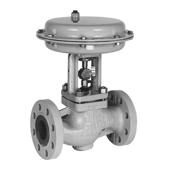
- Page 1 Type 3241 Valve In combination with an actuator, e.g. a SAMSON Type 3271 or Type 3277 Pneumatic Actuator ANSI and JIS version Type 3241 Valve with Type 3271 Actuator (left) and Type 3277 Actuator (right) Mounting and Operating Instructions EB 8012 EN Edition March 2016...
- Page 2 Î For the safe and proper use of these instructions, read them carefully and keep them for later reference. Î If you have any questions about these instructions, contact SAMSON‘s After-sales Service Department (aftersalesservice@samson.de). The mounting and operating instructions for the devices are included in the scope of delivery.
-
Page 3: Table Of Contents
Contents Safety instructions and measures ..............5 Notes on possible severe personal injury ............7 Notes on possible personal injury ..............8 Notes on possible property damage ..............9 Markings on the control valve ..............12 Valve nameplate ..................12 Actuator nameplate ..................13 Material number ..................13 Design and principle of operation ..............14 Fail-safe positions ..................16 Versions ......................16... - Page 4 Contents Maintenance ....................38 Replacing the gasket ..................39 7.1.1 Standard version..................39 7.1.2 Version with insulating section or bellows seal ..........41 Replacing the packing ..................41 7.2.1 Standard version..................41 7.2.2 Version with insulating section ...............42 Replacing the seat and plug ................44 7.3.1 Standard version..................44 7.3.2 Version with insulating section ...............46 Preparation for return shipment ..............47...
-
Page 5: Safety Instructions And Measures
SAMSON must be contacted. SAMSON does not assume any liability for damage resulting from the failure to use the valve for its intended purpose or for damage caused by external forces or any other external factors. - Page 6 Î Check with the plant operator for details on further protective equipment. Revisions and other modifications Revisions, conversions or other modifications to the product are not authorized by SAMSON. They are performed at the user's own risk and may lead to safety hazards, for example. Fur- thermore, the product may no longer meet the requirements for its intended use.
-
Page 7: Notes On Possible Severe Personal Injury
Safety instructions and measures Referenced standards and regulations The control valves comply with the requirements of the European Pressure Equipment Direc- tive 97/23/EC. Valves with a CE marking have a declaration of conformity which includes information about the applied conformity assessment procedure. This declaration of confor- mity is included in the Appendix of these instructions (see section 10.2). -
Page 8: Notes On Possible Personal Injury
Risk of personal injury due to preloaded springs. Valves in combination with pneumatic actuators with preloaded springs are un- der tension. These control valves with SAMSON pneumatic actuators can be identified by the long bolts protruding from the bottom of the actuator. -
Page 9: Notes On Possible Property Damage
Safety instructions and measures WARNING! Risk of burn injuries due to hot or cold components and pipelines. Depending on the process medium, valve components, and pipelines may get very hot or cold and cause burn injuries. Î Allow components and pipelines to cool down or heat up. Î... - Page 10 Risk of valve damage due to the use of unsuitable tools. Certain tools are required to work on the valve. Î Only use tools approved by SAMSON (u AB 0100). Risk of valve damage due to the use of unsuitable lubricants. The lubricants to be used depend on the valve material. Unsuitable lubricants may corrode and damage the valve surface.
- Page 11 Safety instructions and measures EB 8012 EN...
-
Page 12: Markings On The Control Valve
Markings on the control valve 2 Markings on the control valve 2.1 Valve nameplate SAMSON Fig. 1: Valve nameplate 1…5 14 15 16 17 18 1…5 PED (Pressure Equipment Directive), "Art. 3, Abs. 3" ID of the notified body, fluid group, and category... -
Page 13: Actuator Nameplate
Markings on the control valve The valve nameplate (80) in valve sizes NPS ½ to 6 is affixed to the flange (Fig. 2). The valve nameplate in valve sizes NPS 8 and larger is located on the yoke (Fig. 3). Fig. 2: Nameplate on Fig. 3: Nameplate on the flange the yoke 2.2 Actuator nameplate... -
Page 14: Design And Principle Of Operation
A rise in ation signal pressure causes the force acting on The single-seated Type 3241 Globe Valve is the diaphragm in the actuator to increase. preferably combined with a SAMSON The springs are compressed. Depending on Type 3271 or Type 3277 Pneumatic Actuator... - Page 15 Design and principle of operation Fig. 4: Type 3241‑1 Control Valve with Type 3271 Pneumatic Actuator, body up to NPS 6 Body Flange Yoke Seat Plug (with plug stem) Threaded bushing (packing nut) Stem connector nut Lock nut Spring Nuts Packing Body gasket Travel indicator scale...
-
Page 16: Fail-Safe Positions
Design and principle of operation 3.1 Fail-safe positions 3.2 Versions The fail-safe position depends on the actua- The modular design allows an insulating sec- tor used. tion or metal bellows to be fitted to the stan- dard valve version. Depending on how the compression springs are arranged in the pneumatic actuator, the Micro-flow valve version valve has two different fail-safe positions:... -
Page 17: Technical Data
Risk of hearing loss or deafness due More information is available in Da- to loud noise. ta Sheet u T 8012. Wear hearing protection when work- ing near the valve. Compliance The Type 3241 Valve bears both the CE and EAC marks of conformity. EB 8012 EN... - Page 18 Table 1 to Table 3 provide a summary of the dimensions and weights of the standard version of Type 3241 Valve. Table 4 and Table 5 show the dimensions and weights for the Type 3241 Valve with insulating section or bellows seal. The lengths and heights in the di- mensional drawings are shown on p. 22.
- Page 19 Design and principle of operation Table 2: Dimensions of Type 3241 Valve, NPS 8 (DN 200) and larger Valve seat bore 250 250/cast iron up to 200 mm mm and larg- seat bore 21.38 26.50 26.50 26.50 29.00 Class 125 and 150 Length 22.38 27.88 27.88...
- Page 20 Design and principle of operation Table 4: Dimensions and weights for the Type 3241 Valve with insulating section or bellows seal up to NPS 6 (DN 150) ½ ¾ 1½ 2½ Valve size Insulating section or bellows seal 16.10 16.14 17.76 25.04 26.46 Short ≤750 cm²...
- Page 21 Design and principle of operation Table 5: Dimensions and weights for the Type 3241 Valve with insulating section or bellows seal for NPS 8 (DN 200) and larger Version with Insulating section Bellows seal Up to Up to 250 mm 250 mm 200 mm 200 mm seat seat...
- Page 22 Design and principle of operation Dimensional drawings Type 3241 · NPS ½ to 6 (DN 15 to 150) Type 3241 · NPS 8 to 12 (DN 200 to 300) Type 3241 with insulating section or bel- Type 3241 with insulating section or bel- lows seal · NPS ½ to 6 (DN 15 to 150) lows seal ·...
- Page 23 Refer to the following data sheets for more dimensions and weights: u T 8012 for valves with bellows seal, insulating section or heating jacket The associated actuator documentation applies to actuators, e.g. for SAMSON pneu- matic actuators: u T 8310‑1 for Type 3271 and Type 3277 Actuators up to 750 cm² actuator area u T 8310‑2 for Type 3271 Actuator with 1000 cm²...
-
Page 24: Preparation
2. Check the shipment for transportation damage. Report any damage to WARNING! SAMSON and the forwarding agent (re- Risk of lifting equipment tipping and fer to delivery note). risk of damage to lifting accessories due to exceeding the rated lifting ca- 4.1 Unpacking... -
Page 25: Transporting
(e.g. crane or forklift). The welded-on lifting eyelet on Î Leave the control valve in its transport SAMSON actuators is only intended container or on the pallet to transport it. for mounting and removing the actu- Î Observe the transport instructions. - Page 26 Preparation − Prevent the control valve from tilting or than NPS 6. The sling only protects the tipping. control valve from tilting while being lift- ed. Before lifting the control valve, tight- − Do not leave loads suspended when in- en the sling. terrupting work for longer periods of time.
- Page 27 Preparation Version with flanges Version with welding ends 1. Attach one sling to each flange of the 1. Attach one sling to each welding end of body and to the rigging equipment (e.g. the body and to the rigging equipment hook) of the crane or forklift (see Fig. 7).
-
Page 28: Storage
− Observe storage instructions. − Do not place any objects on the control − Avoid long storage times. valve. − Contact SAMSON in case of differ- Special storage instructions for elastomers ent storage conditions or longer storage times. Elastomer, e.g. actuator diaphragm −... -
Page 29: Preparation For Installation
Preparation 4.4 Preparation for installation Proceed as follows: Î Flush the pipelines. Note: The plant engineering company is re- sponsible for cleaning the pipelines in the plant. Î Check the valve to make sure it is clean. Î Check the valve for damage. Î... -
Page 30: Mounting And Start-Up
Mounting and start-up 5 Mounting and start-up 5.1 Mounting the actuator onto the valve SAMSON valves are delivered ready for use. In special cases, the valve and actuator Proceed as described in the actuator docu- are delivered separately and must be assem- mentation if the valve and actuator have not bled on site. -
Page 31: Installing The Valve Into The Pipeline
− Valves with insulating section for low range of the actuator (see associat- temperatures below –10 °C (14 °F) ed actuator documentation). Î Contact SAMSON if the mounting posi- tion is not as specified here. 5.2 Installing the valve into the Support or suspension... - Page 32 Mounting and start-up Table 6: Inlet and outlet lengths Flow rate Inlet length Outlet length a x NPS b x NPS State of process Valve conditions Inlet length a Outlet length b medium Ma ≤ 0.3 0.3 ≤ Ma ≤ 0.7 Ma ≤ 0.3 1) 0.3 ≤ Ma ≤ 0.7 1) Vapor Saturated steam (percentage of condensate > 5 %) Free of cavitation/w < 10 m/s Cavitation producing noise/w ≤ 3 m/s...
-
Page 33: Additional Fittings
WARNING! Risk of personal injury due to compo- Strainers nents under pressure and process We recommend installing a SAMSON medium escaping under pressure. strainer upstream of the valve. It prevents sol- Do not loosen the screw of the test id particles in the process medium from connection while the valve is in oper- damaging the valve. -
Page 34: Quick Check
5.3 Quick check 6. Depending on the field of application, allow the valve to cool down or heat up SAMSON valves are delivered ready for to reach ambient temperature before use. To test the valve's ability to function, the start up. - Page 35 Adjustable packing The plant engineering company is re- sponsible for performing the pressure Tip: test. SAMSON's After‑sales Service A label on the flange (2) or yoke (3) department can support you to plan indicates whether an adjustable and perform a pressure test for your packing is installed.
-
Page 36: Operation
Operation 6 Operation 6.1 Working in manual mode Immediately after completing mounting and Valves fitted with actuators with a handwheel start-up (see section 5), the valve is ready for can be manually closed or opened in case of use. supply air failure. Î... - Page 37 Operation EB 8012 EN...
-
Page 38: Maintenance
WARNING! Tip: Risk of burn injuries due to hot or SAMSON's After‑sales Service de- cold components and pipeline. partment can support you to draw up Valve components and the pipeline a maintenance plan for your plant. -
Page 39: Replacing The Gasket
SAMSON's Af- ter‑sales Service department. Note: The control valve was checked by SAMSON before it left the factory. 7.1.1 Standard version − Certain test results (seat leakage and leak test) certified by 1. Remove the actuator from the valve. See SAMSON lose their validity when associated actuator documentation. - Page 40 Lock nut Actuator Spring Actuator stem Body nut Ring nut Packing Stem connector clamps Packing rings Body gasket Insulating section Fig. 8: Standard version of Type 3241 with Type 3271 Actuator (left) and Type 3241 in version with insulating section (right) EB 8012 EN...
-
Page 41: Version With Insulating Section Or Bellows Seal
(21). To replace the packing in other valve 5. Insert a new gasket (17) into the body. versions, contact SAMSON's After‑ sales Service department. 6. Place the insulating section (21) with valve bonnet (2) and plug with plug stem (5) onto the body. -
Page 42: Standard Version
Maintenance 7.2.1 Standard version 13. Press the plug (5) firmly into the seat (4), while fastening down the flange (2) with Standard packing (PTFE) the body nuts (14). Tighten the nuts gradually in a criss-cross pattern. Ob- 1. Remove the actuator from the valve. See serve tightening torques. - Page 43 Maintenance 15.1 15.2 Valve bonnet Plug with plug stem Threaded bushing (packing nut) Spring Washer Packing 15.1 Shim with retaining ring 15.2 Seals Packing rings Fig. 9: Standard packing (left) and ADSEAL packing (right) 7.2.2 Version with insulating 5. Carefully lift the valve bonnet (2) over the plug stem extension (25).
-
Page 44: Replacing The Seat And Plug
To replace seat and plug in other 1. Proceed as described in “Standard pack- valve versions, contact SAMSON's ing (PTFE)”, steps 1 to 9. After‑sales Service department. 2. Slide the parts of the packing over the... -
Page 45: Standard Version
Maintenance 13. Slide the new plug with plug stem (5) in- Tip: to the valve body (1). When replacing the seat and plug, 14. Place the flange (2) onto the body. we also recommend replacing the Version with V-port plug: place the packing. -
Page 46: Version With Insulating Section
Maintenance 7.3.2 Version with insulating 15. Apply a suitable lubricant to all packing parts and the end of the plug stem of the section new plug (5). 1. Remove the actuator from the valve. See We recommend replacing the packing as associated actuator documentation. -
Page 47: Preparation For Return Shipment
Contact your nearest SAMSON subsidiary 23. Screw in the threaded bushing (8) and or the SAMSON After-sales Service depart- tighten it. Observe tightening torques. ment for information on spare parts, lubri- 24. Loosely screw the lock nut (10) and stem cants, and tools. -
Page 48: Malfunctions
Depending on the operating conditions, check the valve at certain intervals to prevent possi- ble failure before it can occur. Operators are responsible for drawing up a test plan. Tip: SAMSON's After‑sales Service department can support you to draw up an inspection plan for your plant. 8.1 Troubleshooting... -
Page 49: Emergency Action
A label on the flange (2) or yoke (3) indicates whether an adjustable packing is installed. Note: Contact SAMSON's After‑sales Service department for malfunctions not listed in the table. 8.2 Emergency action Putting the valve back into operation after... -
Page 50: Decommissioning And Disassembly
Decommissioning and disassembly 9 Decommissioning and disas- − Allow components and pipelines to cool down or heat up. sembly − Wear protective clothing and gloves. DANGER! Risk of bursting in pressure equip- 9.1 Decommissioning ment. Control valves and pipelines are To decommission the control valve for service pressure equipment. -
Page 51: Removing The Actuator From The Valve
Decommissioning and disassembly 3. Remove the valve from the pipeline (see section 4.2). 9.3 Removing the actuator from the valve See associated actuator documentation. 9.4 Disposal Î Observe local, national, and internation- al refuse regulations. Î Do not dispose of components, lubri- cants, and hazardous substances togeth- er with your other household waste. -
Page 52: Appendix
You can reach the After-sales Service De- partment at aftersalesservice@samson.de. Addresses of SAMSON AG and its subsid- iaries The addresses of SAMSON AG, its subsid- iaries, representatives, and service facilities worldwide can be found on the SAMSON website, in all SAMSON product catalogs or on the back of these Mounting and Operat- ing Instructions. -
Page 53: Certificates
Für folgende Produkte/For the following pressure equipment: Geräte/Devices Bauart/Series Typ/Type Ausführung/Version DIN, Gehäuse GG/Cast iron-Body DN65-125, Gehäuse GGG/Sph. gr. Durchgangsventil/Globe Valve 3241 iron-Body DN50-80, Fluide/Fluids DIN, Geh. Stahl u.a./Body Steel etc., DN40-100 Durchgangsventil/Globe Valve 3241 Fluide/Fluids ANSI, Gehäuse GG/Cast iron-Body, Cl250 1 ½“-2“, Cl125 2 ½“-4“... - Page 54 Für folgende Produkte/For the following pressure equipment: Geräte/Devices Bauart/Series Typ/Type Ausführung/Version Stellgerät für Heißwasser und Dampf mit mit Typ/with Type No. 2811, 2814, 2823, 3321, 3241, 3267 Sicherheitsfunktion/Safety Accessories for 3374 (2000 N) Zertifikat-Nr./Certificate No.: 01 202 931-B-11-0017 Hot Water and Steam 3241-4362, Sicherheitsabsperreinrichtung für...
- Page 55 Bauart/Series Typ/Type Ausführung/Version DIN, Gehäuse GG/Cast iron-Body ab/from DN150, Gehäuse GGG/Sph. Durchgangsventil/Globe Valve 3241 gr. iron-Body ab/from DN100, Fluide/Fluids DIN/ANSI, Geh. Stahl u.a./Body Steel etc., alle Fluide/all Fluids DIN, Gehäuse GG ab DN150/Cast iron-Body from DN150; Gehäuse GGG Dreiwegeventil/Three-way Valve 3244 ab DN100/Sph.
-
Page 56: Declaration Of Conformity
. 2710); 3323, 3535 (2803); 3213, 3531 (2811); 3214 (2814); 2423E Type Model No. (2823); 241 (3241); 244 (3244); 267 (3267); wird hiermit bestätigt, dass sie mit den Anforderungen konform sind, die festgelegt sind in der we declare conformity with the demands of the Richtlinie des Rates zur Angleichung der Rechtsvorschriften vom 29.05.1997... - Page 57 2710); 3226, 3260* (2713*); 3323, 3535 (2803); 3213, 3531 (2811); Type Model No. 3214 (2814); 2423E (2823); 241 (3241); 244 (3244); 267 (3267); wird hiermit bestätigt, dass sie mit den Anforderungen konform sind, die festgelegt sind in der we declare conformity with the demands of the Richtlinie des Rates zur Angleichung der Rechts- vom 29.05.1997...
- Page 58 Appendix EB 8012 EN...
-
Page 59: Spare Parts
Appendix 10.3 Spare parts Legend Screw plug with seal Body Ring/ring nut 1) Flange/valve bonnet Packing ring 1) Yoke Gasket 1) Seat Support 1) Plug (with plug stem) Hexagon screw 1) Guide bushing (flange) Hexagon screw 1) Threaded bushing (packing nut) Lock 1) Stem connector nut... - Page 60 DN 15…150 NPS ½…6 14 33 30 33 EB 8012 EN...
- Page 61 80 81 DN 200…300 80 81 83 84 NPS 8…12 (DN 250, DN 300) (10", 12") 13 91 EB 8012 EN...
- Page 62 EB 8012 EN...
- Page 63 EB 8012 EN...
- Page 64 SAMSON AG · MESS- UND REGELTECHNIK Weismüllerstraße 3 · 60314 Frankfurt am Main, Germany Phone: +49 69 4009-0 · Fax: +49 69 4009-1507 EB 8012 EN samson@samson.de · www.samson.de...
Need help?
Do you have a question about the 3241 and is the answer not in the manual?
Questions and answers