Table of Contents
Advertisement
Quick Links
EB 8020-1 EN
Translation of original instructions
NOTICE on the scope of this document
These mounting and operating instructions
only apply to valves already in use.
For control valves of the valve class D, refer
to the updated mounting and operating
instructions u EB 8020
They can be downloaded from our website
u www.samsongroup.com > Service &
Support > Downloads > Documentation
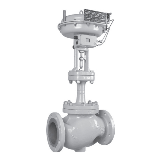
Type 3241‑7‑Gas with Type 3963 Solenoid Valve and Type 3730 Positioner
Type 3241-1-Gas and Type 3241-7-Gas
Automatic Shut-off Valves for Gases
Valve class D and valve class E
Edition February 2020
at
Advertisement
Table of Contents

Related Manuals for Samson 3241-1-Gas


Summary of Contents for Samson 3241-1-Gas
- Page 1 They can be downloaded from our website u www.samsongroup.com > Service & Support > Downloads > Documentation Type 3241‑7‑Gas with Type 3963 Solenoid Valve and Type 3730 Positioner Type 3241-1-Gas and Type 3241-7-Gas Automatic Shut-off Valves for Gases Valve class D and valve class E Edition February 2020...
- Page 2 Note on these mounting and operating instructions These mounting and operating instructions assist you in mounting and operating the device safely. The instructions are binding for handling SAMSON devices. The images shown in these instructions are for illustration purposes only. The actual product may vary.
-
Page 3: Table Of Contents
Contents Safety instructions and measures ..............5 Notes on possible severe personal injury ............8 Notes on possible personal injury ..............8 Notes on possible property damage ..............9 Markings on the device ................12 Nameplate for gas version................12 Valve nameplate ..................13 Actuator nameplate ..................14 Other markings ...................14 2.4.1 DVGW register number ................14... - Page 4 Contents Servicing.....................37 Replacing the gasket ..................38 Other service work ..................39 Aligning the V‑port plug ................39 Cleaning the strainer ..................40 Testing the control valve ................40 Preparation for return shipment ..............40 Ordering spare parts and operating supplies ..........40 Malfunctions ....................43 Troubleshooting ...................43 Emergency action ..................44 Decommissioning and removal ..............45 Decommissioning ..................45...
-
Page 5: Safety Instructions And Measures
SAMSON. SAMSON does not assume any liability for damage resulting from the failure to use the de‑ vice for its intended purpose or for damage caused by external forces or any other external factors. - Page 6 Î Check with the plant operator for details on further protective equipment. Revisions and other modifications Revisions, conversions or other modifications of the product are not authorized by SAMSON. They are performed at the user's own risk and may lead to safety hazards, for example. Fur‑...
- Page 7 Safety instructions and measures Responsibilities of the operator The operator is responsible for proper operation and compliance with the safety regulations. Operators are obliged to provide these mounting and operating instructions as well as the referenced documents to the operating personnel and to instruct them in proper operation. Furthermore, the operator must ensure that operating personnel or third persons are not ex‑...
-
Page 8: Notes On Possible Severe Personal Injury
Safety instructions and measures 1.1 Notes on possible severe personal injury DANGER Risk of bursting in pressure equipment. Valves and pipelines are pressure equipment. Improper opening can lead to valve components bursting. Î Before starting any work on the control valve, depressurize all plant sections affect‑ ed as well as the valve. -
Page 9: Notes On Possible Property Damage
Risk of personal injury due to preloaded springs. Valves in combination with pneumatic actuators with preloaded springs are under ten‑ sion. These control valves with SAMSON pneumatic actuators can be identified by the long bolts protruding from the bottom of the actuator. - Page 10 Risk of valve damage due to the use of unsuitable tools. Certain tools are required to work on the valve. Î Only use tools approved by SAMSON (u AB 0100). Risk of valve damage due to the use of unsuitable lubricants. The lubricants to be used depend on the valve material. Unsuitable lubricants may cor‑...
- Page 11 EB 8020-1 EN...
-
Page 12: Markings On The Device
Markings on the device 2 Markings on the device 2.1 Nameplate for gas version SAMSON AG Stellventil Control Valve Vanne de réglage Auftrags-Nr. Weismüllerstraße 3 Meßstelle Type TAG No. Order No. D-60314 Frankfurt/M de commande Repère Material Characteristic on-off lin. -
Page 13: Valve Nameplate
Markings on the device 2.2 Valve nameplate 14 15 Fig. 2: Inscriptions on the valve nameplate Item Inscription meaning Item Inscription meaning Data Matrix code Noise reduction: 1: flow divider (ST) 1 · 2: ST 2 · 3: ST 3 Type designation 1/PSA: ST 1 standard and integrated in Material seat for PSA valve ·... -
Page 14: Actuator Nameplate
Markings on the device 2.3 Actuator nameplate A100 See associated actuator documentation. 2.4 Other markings 2.4.1 DVGW register number Typ 3241-G 0085 DVGW-PIN Klasse D, p zul. Zul. Außentemp. –20…+60°C Fig. 3: DVGW register number 2.4.2 Material numbers The seat and plug of the valves have an item number written on them. - Page 15 EB 8020-1 EN...
-
Page 16: Design And Principle Of Operation
The process medium flows through the strain‑ The Type 3241G Valve is a single‑seated er and the valve in the direction indicated by globe valve. It is combined with a SAMSON the arrow. A rise in signal pressure causes Type 3271 or Type 3277 Pneumatic Actua‑... - Page 17 Design and principle of operation Pilot valve A26/27 P st Strainer Body Packing Flange Body gasket Seat Bellows seal Plug (with plug stem) Plug stem with metal bellows Threaded bushing (packing nut) Test connection Stem connector nut Actuator stem Lock nut A26/27 Stem connector clamps Body nut Fig. 5: Type 3241‑1‑Gas Automatic Shut‑off Valve...
- Page 18 Design and principle of operation Voltage Fig. 6: Functional diagram showing version without positioner Pilot valve Positioner Switch for safety interlock circuit Voltage P st Fig. 7: Functional diagram showing version with positioner EB 8020-1 EN...
-
Page 19: Fail-Safe Positions
Design and principle of operation 3.1 Fail-safe positions 3.2 Versions The fail‑safe position depends on the mount‑ Actuators ed actuator. Î To select a suitable actuator, see Table 6 Depending on how the compression springs (valve class D) or Table 9 (valve class E). are arranged in the pneumatic actuator, the valve has two different fail‑safe positions: 3.3 Technical data... - Page 20 Design and principle of operation Noise emissions SAMSON is unable to make general state‑ ments about noise emissions. The noise emis‑ sions depend on the valve version, plant fa‑ cilities and process medium. WARNING Risk of hearing loss or deafness due to loud noise.
- Page 21 Design and principle of operation Dimensions and weights Table 2 to Table 4 provide a summary of the dimensions and weights of the standard version of Type 3241 Valve. Dimensions in mm · Weights in kg Table 2: Dimensions for Type 3241G Valve Valve 1) 1) Length L Length L1...
- Page 22 Design and principle of operation Table 4: Weights Valve Weight without kg (approx.) actuator Strainer Weight kg (approx.) Actuator cm² 175v2 355v2 750v2 Weight of kg (approx.) Type 3271 Weight of kg (approx.) Type 3277 Solenoid valve kg (approx.) Dimensional drawings ØD ØD Type 3241‑1‑Gas Type 3241‑7‑Gas EB 8020-1 EN...
-
Page 23: Technical Data Of Version For Valve Class D
Design and principle of operation 3.3.2 Technical data of version for valve class D Table 5: Type 3241G Valve Cast body: DN 15 to 150 · Forged body: DN 15 to 80 DIN DVGW test mark CE-0085CQ0516 Valve size Pressure rating 0.4 1.6 0.4 1.6 6.3 6.3 16 6.3 16 25 40 25 40 60 80 63 100 160 160 260 coefficient (without 2.5 10 10 –... - Page 24 Design and principle of operation Table 7: Pilot valves for Type 3241‑1‑Gas · Valid for closing time <5 s Valve Solenoid valve manufacturer and model number SAMSOMATIC model coefficient Norgren series Herion (attachment: threaded (Attachment: NAMUR interface) Valve size Actuator Fail-safe connection) area [cm²] position 3963-xxxxx13 3963-xxxxx14...
-
Page 25: Technical Data Of Version For Valve Class E
Design and principle of operation 3.3.3 Technical data of version for valve class E Table 8: Type 3241G Valve Cast body: DN 15 to 150 · Forged body: DN 15 to 80 DIN DVGW test CE-0085AQ 0787 -0734 1) mark Valve size 1) Pressure rating 0.4 1.6 0.4 1.6 6.3 6.3 16 6.3 16 25 40 25 40 60 80 60 80 63 100 160 160 160 260 coefficient (without flow... - Page 26 Design and principle of operation Table 9: Types 3271 and 3277 Pneumatic Actuators Actuator area in cm² Signal 1.85 to 1.4 to 0.4 to pressure 1.2 to 2.0 1.4 to 2.3 range Req. bar 2.2 2.4 2.1 2.2 2.6 2.6 2.5 2.6 2.5 supply pressure Max.
-
Page 27: Measures For Preparation
Measures for preparation 4 Measures for preparation 4.2 Transporting and lifting After receiving the shipment, proceed as fol‑ DANGER lows: Risk due to suspended loads falling. 1. Check the scope of delivery. Compare Stay clear of suspended or moving loads. the shipment received with the delivery note. -
Page 28: Transporting
The control valve can be transported using tached slings. lifting equipment (e.g. crane or forklift). The welded‑on lifting eyelet on SAMSON Î Leave the control valve in its transport actuators is only intended for mounting and container or on the pallet to transport it. - Page 29 Measures for preparation − Prevent the control valve from tilting or − Make sure that the sling around the tipping over. strainer is long enough and that the load that it bears is not too heavy. The sling − Do not leave loads suspended when in‑ must not bend the strainer upwards and terrupting work for longer periods of not place strain on the flanged joint.
-
Page 30: Storage
Elastomer, e.g. actuator diaphragm − Avoid long storage times. − To keep elastomers in shape and to pre‑ − Contact SAMSON in case of different stor‑ vent cracking, do not bend them or hang age conditions or long storage periods. -
Page 31: Preparation For Installation
Measures for preparation 4.4 Preparation for installation Proceed as follows: Î Flush the pipelines. Note The plant operator is responsible for clean‑ ing the pipelines in the plant. Î Check the valve to make sure that it is clean. Î Check the valve for damage. Î... -
Page 32: Mounting And Start-Up
Valve and actuator are delivered ready Î Contact SAMSON if the mounting posi‑ mounted. tion is not as specified above. Support and suspension Depending on the valve version and mount‑... -
Page 33: Additional Fittings
Mounting and start-up Table 11: Inlet and outlet lengths Flow rate Inlet length Outlet length a x DN b x DN State of process Valve conditions Inlet length a Outlet length b medium Ma ≤ 0.3 0.3 ≤ Ma ≤ 0.7 Î On mounting valve accessories, make NOTICE sure that they can be operated from the Premature wear and leakage due to insuffi‑... -
Page 34: Installing The Control Valve
5.3 Quick check WARNING Risk of personal injury due to pressurized SAMSON valves are delivered ready for components and process medium escaping use. To test the valve's ability to function, the under pressure. following quick checks can be performed: Do not loosen the screw of the test connec‑... - Page 35 Mounting and start-up Note The plant operator is responsible for performing the pressure test. SAMSON's After‑sales Service can support you to plan and perform a pressure test for your plant. EB 8020-1 EN...
-
Page 36: Operation
Operation 6 Operation Immediately after completing mounting and start‑up (see section 5), the valve is ready for use. WARNING Crush hazard arising from moving parts (ac‑ tuator and plug stem). Do not insert hands or fingers into the yoke while the valve is in operation. WARNING Risk of personal injury when the actuator vents. -
Page 37: Servicing
WARNING Risk of burn injuries due to hot or cold com‑ ponents and pipeline. SAMSON's After‑sales Service can support Valve components and the pipeline may be‑ you in drawing up an inspection and test come very hot or cold. Risk of burn injuries. -
Page 38: Replacing The Gasket
5. Insert a new gasket (17) into the body. 6. Place the bellows seal (22) with valve Note bonnet (2) and plug with plug stem (5) The control valve was checked by SAMSON onto the body. before it left the factory. Version with V-port plug: place the as‑... -
Page 39: Other Service Work
The process medium in the valve flows To replace seat and plug, packing or bellows through the V‑shaped ports as soon as the seal, contact SAMSON's After‑sales Service. plug is lifted out of the seat (i.e. the valve opens). -
Page 40: Cleaning The Strainer
Support > Checklists for after‑sales ser‑ vice > Declaration on Contamination. 4. Send the valve together with the filled‑in 7.4 Cleaning the strainer form to your nearest SAMSON subsidi‑ ary. SAMSON subsidiaries are listed on See associated device documentation. our website at u www.samsongroup.com >... - Page 41 Servicing Table 12: Required tests Seat leakage testing Standard IEC 60534‑4 or ANSI/FCI 70‑2 Test medium Use dry compressed air free of oil and grease Inlet: 4 bar (standard); max. 40 bar Test pressure Outlet: atmospheric pressure or connection to a flow meter 1. Move the plug out of the seat (valve closed). 2.
- Page 42 Servicing Tools See document u AB 0100 for details on suitable tools. EB 8020-1 EN...
-
Page 43: Malfunctions
Depending on the operating conditions, check the valve at certain intervals to prevent a pos‑ sible failure before it can occur. Operators are responsible for drawing up an inspection and test plan. SAMSON's After‑sales Service can support you in drawing up an inspection and test plan for your plant. 8.1 Troubleshooting... -
Page 44: Emergency Action
Malfunctions Note Contact SAMSON's After‑sales Service for malfunctions not listed in the table. 8.2 Emergency action Upon supply air or control signal failure, the valve moves to its fail‑safe position (see sec‑ tion 3.1). The plant operator is responsible for emer‑... -
Page 45: Decommissioning And Removal
Decommissioning and removal 9 Decommissioning and 9.1 Decommissioning removal To decommission the control valve for service and repair work or disassembly, proceed as follows: DANGER Risk of bursting in pressure equipment. 1. Depressurize the plant. Valves and pipelines are pressure equip‑ 2. -
Page 46: Annex
You can reach our after‑sales service at af‑ tersalesservice@samson.de. Addresses of SAMSON AG and its subsid- iaries The addresses of SAMSON AG, its subsid‑ iaries, representatives and service facilities worldwide can be found on our website (www.samson.de) or in all SAMSON prod‑... - Page 47 SAMSON erklärt in alleiniger Verantwortung für folgende Produkte: Stellventil Typ 3241-1-Gas (mit pneumatischem Antrieb Typ 3271) Stellventil Typ 3241-7-Gas (mit pneumatischem Antrieb Typ 3277) die Konformität mit nachfolgender Anforderung: Verordnung des Europäischen Parlaments und des Rates über Geräte zur Verbrennung gasförmiger Brennstoffe und zur (EU) 2016/426 9.
- Page 48 Modul/Module D / N° CE-PED-D-SAM 001-13-DEU SAMSON erklärt in alleiniger Verantwortung für folgende Produkte/explaines in sole resposibility for the following products: Geräte/Devices Bauart/Series Typ/Type Ausführung/Version Stellgerät für Heißwasser und Dampf mit Typ/with Type No. 2811, 2814, 2823, 3321, 3241, 3267...
- Page 49 EB 8020-1 EN...
- Page 50 EB 8020-1 EN...
- Page 51 EB 8020-1 EN...
- Page 52 EB 8020-1 EN...
-
Page 53: Spare Parts
10.3 Spare parts Body (valve) Top diaphragm case Flange Bottom diaphragm case Seat Diaphragm Plug (with plug stem) Diaphragm plate Guide bushing (flange) Hose clamp Threaded bushing (packing nut) Actuator stem Stem connector nut Ring nut Lock nut Hex nut Spring A10/ Spring... - Page 54 A20/22 A106 A100 A26/27 EB 8020-1 EN...
- Page 55 EB 8020-1 EN...
- Page 56 EB 8020-1 EN SAMSON AKTIENGESELLSCHAFT Weismüllerstraße 3 · 60314 Frankfurt am Main, Germany Phone: +49 69 4009-0 · Fax: +49 69 4009-1507 samson@samsongroup.com · www.samsongroup.com...
Need help?
Do you have a question about the 3241-1-Gas and is the answer not in the manual?
Questions and answers