
Related Manuals for Samson 3248


Summary of Contents for Samson 3248
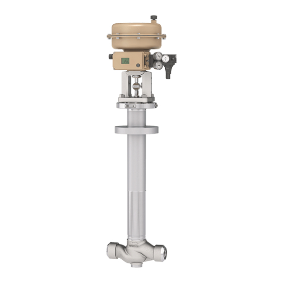
- Page 1 Type 3248 Valve In combination with an actuator, e.g. a SAMSON Type 3271 or Type 3277 Pneumatic Actuator DIN version Mounting and Operating Instructions EB 8093 EN Edition November 2016...
- Page 2 Î For the safe and proper use of these instructions, read them carefully and keep them for later reference. Î If you have any questions about these instructions, contact SAMSON‘s After-sales Service Department (aftersalesservice@samson.de). The mounting and operating instructions for the devices are included in the scope of delivery.
-
Page 3: Table Of Contents
Contents Safety instructions and measures ..............5 Notes on possible severe personal injury ............8 Notes on possible personal injury ..............9 Notes on possible property damage ..............10 Markings on the control valve ..............12 Valve nameplate ..................12 Actuator nameplate ..................13 Material number ..................13 Design and principle of operation ..............14 Fail-safe positions ..................17 Versions ......................17... - Page 4 Contents Servicing.....................42 Replacing the gasket ..................43 7.1.1 Globe or angle valve, PN 16 to 40 ...............43 7.1.2 Globe or angle valve, PN 63 and 100............44 Replacing the packing ..................45 7.2.1 Globe or angle valve, PN 16 to 40 ...............45 7.2.2 Globe or angle valve, PN 63 and 100............46 Replacing the seat and plug ................47 Replacing the bellows seal ................47 Preparation for return shipment ..............47...
-
Page 5: Safety Instructions And Measures
SAMSON must be contacted. SAMSON does not assume any liability for damage resulting from the failure to use the valve for its intended purpose or for damage caused by external forces or any other external factors. - Page 6 Î Check with the plant operator for details on further protective equipment. Revisions and other modifications Revisions, conversions or other modifications to the product are not authorized by SAMSON. They are performed at the user's own risk and may lead to safety hazards, for example. Fur- thermore, the product may no longer meet the requirements for its intended use.
- Page 7 Safety instructions and measures Referenced standards and regulations The control valves comply with the requirements of the European Pressure Equipment Direc- tive 2014/68/EU. Valves with a CE marking have a declaration of conformity, which in- cludes information about the applied conformity assessment procedure. This declaration of conformity is included in the Appendix of these instructions (see section 10.2).
-
Page 8: Notes On Possible Severe Personal Injury
Î Wear personal protective equipment. Risk of injury due to incorrect handling of oxygen or cryogenic gases. The Type 3248 Valve is frequently used for oxygen service or applications with cryo- genic gases. Oxygen is a hazardous substance, which reacts quickly, leading to com- bustion or explosions. -
Page 9: Notes On Possible Personal Injury
Risk of personal injury due to preloaded springs. Valves in combination with pneumatic actuators with preloaded springs are under ten- sion. These control valves with SAMSON pneumatic actuators can be identified by the long bolts protruding from the bottom of the actuator. -
Page 10: Notes On Possible Property Damage
Risk of valve damage due to the use of unsuitable tools. Certain tools are required to work on the valve. Î Only use tools approved by SAMSON (u AB 0100). Risk of valve damage due to the use of unsuitable lubricants. The lubricants to be used depend on the valve material. Unsuitable lubricants may corrode and damage the valve surface. - Page 11 Safety instructions and measures EB 8093 EN...
-
Page 12: Markings On The Control Valve
Markings on the control valve 2 Markings on the control valve 2.1 Valve nameplate SAMSON Fig. 1: Valve nameplate 1…5 14 15 16 17 1…5 PED (Pressure Equipment Directive), "Art. 4, Abs. 3" ID of the notified body, fluid group, and category... -
Page 13: Actuator Nameplate
Markings on the control valve The nameplate is affixed to the valve bonnet (see Fig. 2). 2.2 Actuator nameplate See associated actuator documentation. 2.3 Material number The seat and plug of the valves have an arti- cle number written on them. Specifying this article number, you can contact us to find out which material is used. -
Page 14: Design And Principle Of Operation
The packing consists of a spring-load- The Type 3248 is available in the following ed PTFE-carbon V-ring packing. versions: In the PN 16 to 40 version, the valve bonnet (2) is designed as a yoke (see Fig. 3). - Page 15 Bonnet gasket Plug stem with metal bellows A26/27 Bellows nut Test connection Spacer stem Actuator stem A26/27 Stem connector clamps Cover plate Fig. 3: Type 3248 Globe Valve with stainless steel body (PN 16 to 40) and with Type 3271 Pneumatic Actuator EB 8093 EN...
- Page 16 Design and principle of operation Fig. 4: Type 3248 Angle Valve with stainless steel Fig. 5: Type 3248 Angle Valve with aluminum body (PN 100) body (PN 16 to 40) EB 8093 EN...
-
Page 17: Fail-Safe Positions
Actuator stem extends (FA) Larger nominal sizes When the signal pressure is reduced or the The Type 3248 Valve is available up to nom- air supply fails, the springs move the actua- inal size DN 200. tor stem downward and close the valve. The... -
Page 18: Technical Data
WARNING Risk of hearing loss or deafness due to loud Compliance noise. The Type 3248 Valve bears both the CE and Wear hearing protection when working near EAC marks of conformity. the valve. Dimensions and weights Table 1 to Table 5 provide a summary of the... - Page 19 Design and principle of operation Note Height H7 is the minimum clearance for ser- vice work. The actuator dimensions must also be observed. The largest value applies. Height H1 and the specified weights are ref- erence values. The exact dimensions and weights depend on various factors, e.g.
- Page 20 Design and principle of operation Table 2: Dimensions of globe valve with stainless steel body, PN 63 and 100 Valve 1298 1050 1100 1100 Ød Welding ends/ Ø33.7 Ø48.3 Ø60.3 Ø88.9 Ø114.3 Ø168.3 pipe connection x 3.2 x 3.6 x 5.6 x 6.3 x 7.1 Dimension H1 + 85 mm applies when 1400-120 cm²...
- Page 21 Design and principle of operation Table 4: Dimensions of angle valve with stainless steel body, PN 100 Valve 795.5 1210 400/600 400/600 400/600 400/600 500/600 550/600 510/710 515/715 515/715 498/698 645/745 649/699 1050 1100 1100 Ød Welding ends/ Ø33.7 Ø48.3 Ø60.3 Ø88.9 Ø114.3 Ø168.3 pipe connection...
- Page 22 Design and principle of operation Dimensional drawings Ød Ød Globe valve with stainless steel body Angle valve with stainless steel body Angle valve with aluminum body Ød EB 8093 EN...
- Page 23 Angle valve in stainless steel version with aluminum body, PN 16 to 40 Weight 130.5 Note Refer to the following data sheets for dimensions and weights of the SAMSON pneumatic actuators: u T 8310‑1 for Type 3271 and Type 3277 Actuators up to 750 cm² actuator area u T 8310‑2 for Type 3271 Actuator with 1000 cm² actuator area and larger u T 8310‑3 for Type 3271 Actuator with 1400‑60 cm²...
-
Page 24: Measures For Preparation
2. Check the shipment for transportation WARNING damage. Report any damage to Risk of lifting equipment tipping and risk of SAMSON and the forwarding agent (re- damage to lifting accessories due to exceed- fer to delivery note). ing the rated lifting capacity. -
Page 25: Transporting
Risk of valve damage due to incorrectly at- tached slings. − Protect the control valve against external The welded-on lifting eyelet on SAMSON influences (e.g. impact). actuators is only intended for mounting and − Do not damage the corrosion protection removing the actuator as well as lifting the (paint, surface coatings). -
Page 26: Lifting
Measures for preparation 4.2.2 Lifting To install a large valve into the pipeline, use − We recommend using a hook with safety lifting equipment (e.g. crane or forklift) to lift latch (see Fig. 9). The safety latch prevents the slings from slipping during lifting and transporting. - Page 27 Measures for preparation Lifting with the actuator mounted 4. Move the control valve at an even pace to the site of installation. The control valve can be lifted in the hori- zontal position either using one hook (Fig. 6) 5. Install the valve into the pipeline (see sec- or using several hooks on a beam (Fig. 7).
- Page 28 Measures for preparation Lifting with the protective cover mounted − Make sure that the axis of the pipeline is always horizontal during lifting and the 1. Attach two slings to the cryogenic exten- axis of the plug stem is always vertical. sion bonnet and to the rigging equip- ment (e.g.
- Page 29 Measures for preparation Fig. 9: Lifting points on the control valve: globe valve (left) and angle valve (right) EB 8093 EN...
-
Page 30: Storage
2. Secure the slings attached to the body − Avoid long storage times. against slipping using a connector. − Contact SAMSON in case of different stor- 3. 700 cm² and larger: attach another age conditions or long storage periods. sling to the lifting eyelet on the actuator and to the rigging equipment. -
Page 31: Preparation For Installation
Measures for preparation 4.4 Preparation for installation Note Contact SAMSON's After-sales Service de- Proceed as follows: partment for the storage temperatures of oth- Î Flush the pipelines. er valve versions. Note − Do not place any objects on the control The plant operator is responsible for clean- valve. -
Page 32: Mounting And Start-Up
We recommend mounting the valve at an (u AB 0100). angle between 15 and 25° to the horizontal plane. Î Contact SAMSON if the mounting posi- tion is not as specified above. Support or suspension Depending on the valve version and mount- ing position, the control valve and pipeline must be supported or suspended. - Page 33 Mounting and start-up Table 7: Inlet and outlet lengths Flow rate Inlet length Outlet length a x DN b x DN State of process Valve conditions Inlet length a Outlet length b medium Ma ≤ 0.3 0.3 ≤ Ma ≤ 0.7 Free of cavitation/w < 10 m/s Cavitation producing noise/w ≤ 3 m/s Liquid Cavitation producing noise/3 < w < 5 m/s Critical cavitation/w ≤ 3 m/s...
-
Page 34: Additional Fittings
Mounting and start-up 3. Lift the valve using suitable lifting equip- Note ment to the site of installation (see sec- The workplace of operating personnel is the tion 4.2.2). Observe the flow direction location from which the valve, actuator, and through the valve. The arrow on the any mounted valve accessories can be ac- valve indicates the direction of flow. -
Page 35: Removing The Protective Cover
Mounting and start-up 5.2 Removing the protective Removing the protective cover cover 1. Remove nuts (33) and washers (95.9). 2. Turn the adjustment bolt (95.2) counter- To keep the overall height of valves for cold- clockwise. The plug is lowered and the box applications during transportation, the protective cover is lifted off the body. - Page 36 Mounting and start-up 95.3 PN 16 to 40 95.4 95.9 95.1 95.6 95.5 95.7 95.2 Body 95.2 Stud/adjustment bolt 95.3 Axial retaining ring Valve bonnet 95.4 O-ring Yoke 95.5 Gasket Stem connector nut 95.6 Screw plug (test Lock nut connection) Bonnet gasket 95.7 O-ring (glued) Bolt 95.9 Washer (spacer sleeve)
-
Page 37: Mounting The Actuator Onto The Valve
Make sure the V-port plug is installed Proceed as described in the actuator docu- correctly. mentation if the valve and actuator have not been assembled by SAMSON. If a protective cover is mounted, first remove Information it and mount the valve bonnet (see sec- −... -
Page 38: Quick Check
5.4 Quick check Pressure test with mounted protective cover With a mounted protective cover, perform SAMSON valves are delivered ready for the test pressure with an open valve as well use. To test the valve's ability to function, the as with a closed valve. - Page 39 Mounting and start-up Note The plant operator is responsible for performing the pressure test. SAMSON's After-sales Service department can support you to plan and perform a pressure test for your plant. EB 8093 EN...
-
Page 40: Operation
Operation 6 Operation 6.1 Working in manual mode Immediately after completing mounting and Valves fitted with actuators with a handwheel start-up (see section 5), the valve is ready for can be manually closed or opened in case of use. supply air failure. Î... - Page 41 EB 8093 EN...
-
Page 42: Servicing
Depending on the process medium, valve components and pipelines may get extremely SAMSON's After-sales Service department cold and cause cryogenic burns. can support you to draw up an inspection − Allow components and pipelines to cool plan for your plant. -
Page 43: Replacing The Gasket
4. Remove the gasket (17). Carefully clean the sealing faces in the valve bonnet (2) Note and on the body (1). The control valve was checked by SAMSON 5. Insert a new gasket (17) into the body before it left the factory. (1). -
Page 44: Globe Or Angle Valve, Pn 63 And 100
Servicing Body Stem connector nut Plug stem with metal bellows Valve bonnet Lock nut Spacer stem Yoke Bonnet gasket Castellated nut Threaded bushing Bolt (packing nut) Fig. 12: Valve bonnet: PN 16 to 40 (left) · PN 63 and 100 (right) 7.1.2 Globe or angle valve, 4. -
Page 45: Replacing The Packing
(71). To replace the packing in other valve ver- 12. Fasten the valve bonnet (2) using the nuts sions, contact SAMSON's After-sales Service (33) and bolts (32). Tighten the nuts department. gradually in a criss-cross pattern. Ob- serve tightening torques. -
Page 46: Globe Or Angle Valve, Pn 63 And 100
Servicing Valve bonnet 12 Washer 19 Bushing Threaded bushing 15 Packing 71 Spacer stem 11 Spring 16 V-ring packing Fig. 13: Packing 14. Loosely screw the lock nut (10) and stem 4. Unscrew the threaded bushing (8). connector nut (9) onto the spacer stem 5. -
Page 47: Replacing The Seat And Plug
Risk of control valve damage due to incorrect ary. SAMSON subsidiaries are listed on service or repair. our website at u www.samson.de > To replace seat and plug in the Type 3248 Contact. Valve, contact SAMSON's After-sales Ser- vice department. 7.6 Ordering spare parts and operating supplies 7.4 Replacing the bellows seal... -
Page 48: Malfunctions
Depending on the operating conditions, check the valve at certain intervals to prevent possi- ble failure before it can occur. Operators are responsible for drawing up an inspection plan. SAMSON's After-sales Service department can support you to draw up an inspection plan for your plant. -
Page 49: Emergency Action
Malfunctions Note Contact SAMSON's After-sales Service department for malfunctions not listed in the table. 8.2 Emergency action Upon supply air or control signal failure, the valve moves to its fail-safe position (see sec- tion 3.1). The plant operator is responsible for emer- gency action to be taken in the plant. -
Page 50: Decommissioning And Disassembly
Decommissioning and disassembly 9 Decommissioning and disas- 9.1 Decommissioning sembly To decommission the control valve for service and repair work or disassembly, proceed as follows: DANGER Risk of bursting in pressure equipment. 1. Close the shut-off valves upstream and Control valves and pipelines are pressure downstream of the control valve to stop equipment. - Page 51 Decommissioning and disassembly Î Do not dispose of components, lubri- cants, and hazardous substances togeth- er with your other household waste. EB 8093 EN...
-
Page 52: Appendix
You can reach the After-sales Service De- partment at aftersalesservice@samson.de. Addresses of SAMSON AG and its subsid- iaries The addresses of SAMSON AG, its subsid- iaries, representatives, and service facilities worldwide can be found on the SAMSON website, in all SAMSON product catalogs or on the back of these Mounting and Operat- ing Instructions. - Page 53 Modul/Module H / N° CE-PED-H-SAM 001-13-DEU SAMSON erklärt in alleiniger Verantwortung für folgende Produkte/explaines in sole resposibility for the following products: Geräte/Devices Bauart/Series Typ/Type Ausführung/Version DIN, Gehäuse GG/Cast iron-Body ab/from DN150, Gehäuse GGG/Sph. gr. iron-Body ab/from DN100, Fluide/Fluids G2, L1, L2...
- Page 54 EB 8093 EN...
-
Page 55: Spare Parts
Appendix 10.3 Spare parts Body Spacer stem Valve bonnet Plate (direction of flow) Yoke Nameplate Seat Grooved pin Plug (with plug stem) Fillister head screw Guide bushing Hanger Threaded bushing (packing nut) Travel indicator scale Stem connector nut Castellated nut Lock nut Support nut Spring... - Page 56 PN 63…100 PN 16…40 EB 8093 EN...
- Page 57 Globe valve with stainless steel body PN 16…40 PN 63…100 EB 8093 EN...
- Page 58 DN 25…100/PN 16…40 DN 15…150/PN 16…40 EB 8093 EN...
- Page 59 Angle valve with aluminum body EB 8093 EN...
- Page 60 SAMSON AG · MESS- UND REGELTECHNIK Weismüllerstraße 3 · 60314 Frankfurt am Main, Germany Phone: +49 69 4009-0 · Fax: +49 69 4009-1507 EB 8093 EN samson@samson.de · www.samson.de...
Need help?
Do you have a question about the 3248 and is the answer not in the manual?
Questions and answers