
Related Manuals for Samson 3244-1


Summary of Contents for Samson 3244-1
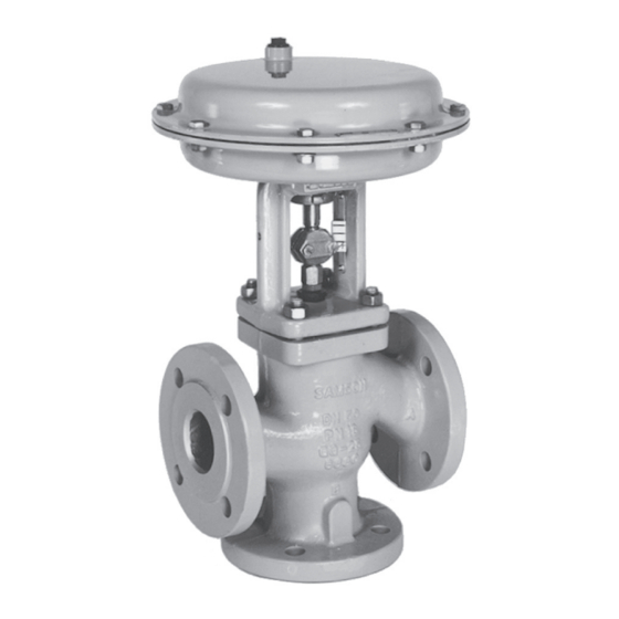
- Page 1 Type 3244-1 and Type 3244-7 Pneumatic Control Valves Type 3244 1 (left) and Type 3244-7 (right) Mounting and Operating Instructions EB 8026 EN Edition July 2014...
- Page 2 Definition of signal words DANGER! NOTICE Hazardous situations which, if not Property damage message or mal- avoided, will result in death or seri- function ous injury Note: WARNING! Additional information Hazardous situations which, if not avoided, could result in death or seri- Tip: ous injury Recommended action...
-
Page 3: Table Of Contents
Contents General safety instructions ................4 Design and principle of operation ..............6 Assembling valve and actuator ..............8 Assembly and adjustment ................8 Installation ....................9 Mounting position ..................9 Arrangement of the valve ................9 Signal pressure line ..................9 Strainer, bypass .....................9 Test connection.....................10 Operation ....................12 Maintenance –... -
Page 4: General Safety Instructions
General safety instructions 1 General safety instructions WARNING! − The control valves are to be mounted, started up or serviced by fully trained and qualified personnel only; the accepted industry codes and practices are to be ob- served. Make sure employees or third persons are not exposed to any danger. −... - Page 5 General safety instructions Note: According to the ignition risk assessment performed in accordance with EN 13463-1: 2001, section 5.2, the non-electrical actuators and valves do not have their own po- tential ignition source even in the rare incident of an operating fault. As a result, they do not fall within the scope of Directive 94/9/EC.
-
Page 6: Design And Principle Of Operation
Fail-safe position ation Depending on how the compression springs are arranged in the actuator, the valve has The Type 3244-1 and Type 3244-7 Pneu- two different fail-safe positions: matic Control Valves consist of the Actuator stem extends Type 3244 Three-way Valve and either a Type 3271 or Type 3277 Pneumatic Actua-... - Page 7 Design and principle of operation Nuts Threaded bushing Gasket Travel indicator scale Type 3277 Actuator Top seat Plug stem Bottom seat Stem connector nut Plug Lock nut Plug section Stem connector Screw Actuator Spring Actuator stem Packing Valve bonnet Type 3271 Actuator Plug arrangement for diverting service DN 32 to 150 Plug arrangement for mixing service,...
-
Page 8: Assembling Valve And Actuator
For actuators with "actuator stem re- Proceed as follows if the valve and actuator tracts" fail-safe action, apply a signal have not been assembled by SAMSON or if pressure that corresponds to the upper the actuator is to be replaced by an actuator bench range value (e.g. -
Page 9: Installation
"actuator stem ex- and downstream of the valve. Con- tends" fail-safe action to the connection on tact SAMSON if this distance cannot the bottom diaphragm case, and for valves be observed. with an actuator with "actuator stem re- Flush the pipeline thoroughly before tracts"... -
Page 10: Test Connection
Installation We recommend installing a shut-off valve both upstream of the strainer and down- stream of the valve to ensure that the plant does not need to be shut down for mainte- nance. In addition, install a bypass line. 4.5 Test connection Versions with bellows seal (Fig. 4) fitted with a test connection (G ) at the top flange al-... - Page 11 Installation Mixing service Diverting service Temperature control Q = constant Flow control Q = 0 to 100 % Fail-safe action: FA = "Actuator stem extends", FE = "Actuator stem retracts" In heating applications with FA, the heating medium (flow) is shut off in the fail-safe position, in cooling applications with FE, cooling is maintained in the fail-safe position.
-
Page 12: Operation
(8.2) can be un- ment u EB 029 EN. screwed. Contact your nearest SAMSON sub- sidiary or the SAMSON After-sales 1. Remove the stem connector (7) and un- Service department for information screw the ring nut (8.2). -
Page 13: Standard Valve Version
Maintenance – Replacing parts 2. Remove the actuator from the valve bon- 15. Loosely screw the lock nut (6.2) and stem net. connector nut (6.1) onto the plug stem. 16. Mount the actuator. Refer to section 3.1. 6.1 Standard valve version 17. Adjust the upper and lower bench range values. -
Page 14: Seat And Plug
(6). 6.2 Valve with insulating sec- Mixing valve tion or bellows seal 5. Unscrew the top seat ring (2.1) using a SAMSON seat wrench. 6.2.1 Packing 6. Lift out the plug stem (6) along with the plug (3). - Page 15 Maintenance – Replacing parts Nuts Gasket Plug Plug section Screws Packing Bonnet Gasket Threaded bushing Travel indicator scale Bolts Plug stem Stem connector nut Lock nut Plug stem extension Washers DN 15 to 80, order no. 8392-2317 DN 100 to 150, order no. 8382-2321 Metal bellows Test connection Intermediate piece...
-
Page 16: Seat And Plug
16. Mount the actuator. Refer to section 3.1. 7. Use the SAMSON plug tool to unscrew 17. Adjust the upper and lower bench range the plug out of the plug stem extension. -
Page 17: Metal Bellows
Maintenance – Replacing parts 6.2.4 Assembly 7. Lift the intermediate piece (12) along with the plug stem extension, plug stem 1. Insert the new gasket (1.2) into the body. and plug (3) out of the valve body (1). 2. Place on the intermediate piece (12) and 8. -
Page 18: Material Number
Material number 7 Material number 8 Description of nameplates Guide bushing, seat and plug have the fol- SAMSON lowing identifying marks: Guide bushing (groove on plane face) 11 12 − No groove: 1.4104 − Sharp recessed groove: 1.4404 CE marking or "Art. 3, Abs. 3", where −... -
Page 19: Customer Inquiries
Customer inquiries 9 Customer inquiries SAMSON Please submit the following details: − Order number − Type, position and nominal size of the Type designation Modification index valve Effective area − Pressure and temperature of the process Fail-safe action: medium FA Actuator stem extends −... - Page 20 SAMSON AG · MESS- UND REGELTECHNIK Weismüllerstraße 3 · 60314 Frankfurt am Main, Germany Phone: +49 69 4009-0 · Fax: +49 69 4009-1507 EB 8026 EN samson@samson.de · www.samson.de...
Need help?
Do you have a question about the 3244-1 and is the answer not in the manual?
Questions and answers