Table of Contents
Advertisement
Quick Links
Advertisement
Table of Contents

Related Manuals for Samson EB 8015 EN


Summary of Contents for Samson EB 8015 EN
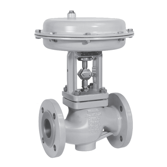
- Page 1 EB 8015 EN Translation of original instructions Type 3241 Valve with Type 3271 Actuator (left) and Type 3277 Actuator (right) Type 3241 Valve · DIN version In combination with an actuator, e.g. a Type 3271 or Type 3277 Pneumatic Actuator Edition April 2024...
- Page 2 Note on these mounting and operating instructions These mounting and operating instructions assist you in mounting and operating the device safely. The instructions are binding for handling SAMSON devices. The images shown in these instructions are for illustration purposes only. The actual product may vary.
-
Page 3: Table Of Contents
Mounting the external anti-rotation fixture .............5-4 5.3.2 Mounting the actuator onto the valve ............5-9 5.3.3 Installing the valve into the pipeline ............5-12 Testing the installed valve ................5-12 5.4.1 Leakage ....................5-14 5.4.2 Travel motion ....................5-15 5.4.3 Fail-safe position ..................5-15 5.4.4 Pressure test ....................5-15 EB 8015 EN... - Page 4 Removal ....................11-1 11.1 Removing the valve from the pipeline ............11-2 11.2 Removing the actuator from the valve ............11-2 Repairs ....................12-1 12.1 Returning devices to SAMSON ..............12-1 Disposal ....................13-1 Certificates ....................14-1 Appendix ....................15-1 15.1 Tightening torques, lubricants and tools ............15-1 15.2 Spare parts ....................15-1...
-
Page 5: Safety Instructions And Measures
SAMSON. SAMSON does not assume any liability for damage resulting from the failure to use the de- vice for its intended purpose or for damage caused by external forces or any other external factors. - Page 6 (see associated actuator documentation). When the valve is combined with a SAMSON Type 3271 or Type 3277 Pneumatic Actuator, the valve moves to a certain fail- safe position (see the 'Design and principle of operation' chapter) upon supply air or control signal failure.
- Page 7 Start-up and shutdown procedures fall within the scope of the operator's duties and, as such, are not part of these mounting and operating instructions. SAMSON is unable to make any statements about these procedures since the operative details (e.g. differential pressures and temperatures) vary in each individual case and are only known to the operator.
- Page 8 SAMSON > Environment, Social & Governance > Material Compliance > REACH If a device contains a substance listed as a substance of very high concern on the candi- date list of the REACH regulation, this is indicated on the SAMSON delivery note. EB 8015 EN...
-
Page 9: Notes On Possible Severe Personal Injury
Î Install the control valve in such a way that vent openings are not located at eye level and the actuator does not vent at eye level in the work position. Î Use suitable mufflers and vent plugs. Î Wear eye protection when working in close proximity to the control valve. EB 8015 EN... - Page 10 Risk of personal injury due to preloaded springs. Valves in combination with pneumatic actuators with preloaded springs are under ten- sion. These control valves with SAMSON pneumatic actuators can be identified by the long bolts protruding from the bottom of the actuator.
-
Page 11: Notes On Possible Property Damage
Î Observe the specified tightening torques (u AB 0100). Risk of valve damage due to the use of unsuitable tools. Certain tools are required to work on the valve. Î Only use tools approved by SAMSON (u AB 0100). EB 8015 EN... -
Page 12: Notes On The Use Of An Rfid Tag
The lubricants to be used depend on the valve material. Unsuitable lubricants may cor- rode and damage surfaces. Î Only use lubricants approved by SAMSON (u AB 0100). Risk of the process medium being contaminated through the use of unsuitable lubri- cants and/or contaminated tools and components. -
Page 13: Markings On The Device
M: mixing valve · V: diverting valve Fig. 2-3 and the inscription table list all pos- sible characteristics and options that may appear on a valve nameplate. Only the in- scriptions relevant to the ordered Type 3241 Valve actually appear on the nameplate. EB 8015 EN... -
Page 14: Actuator Nameplate
15 Noise reduction: 1: flow divider (ST) 1 · 2: ST 2 · by SAMSON. The material number enables 3: ST 3 · 1/PSA: ST 1 standard and inte- you to view the device's technical data as grated in seat for PSA valve ·... -
Page 15: Label When An Adjustable Packing Is Installed
Data Matrix code on the elec- tronic nameplate. It can be read using a smartphone, tablet or RFID reader. Application range according to the technical data (see the 'Design and principle of opera- tion' chapter). EB 8015 EN... - Page 16 EB 8015 EN...
-
Page 17: Design And Principle Of Operation
Fail-safe action globe valve. This valve is preferably com- The fail-safe position of the control valve up- bined with a SAMSON Type 3271 or on air supply or control signal failure de- Type 3277 Pneumatic Actuator. It can also pends on the actuator used (see associated be combined with other actuators. - Page 18 Plug (with plug stem) Threaded bushing (packing nut) Stem connector nut Lock nut Spring Nuts Packing Body gasket Travel indicator scale Castellated nut Actuator Actuator stem Ring nut A26 Stem connector clamps Fig. 3-2: Type 3241 Valve, body DN 200 to 300 EB 8015 EN...
-
Page 19: Versions
(see Information Sheet u T 8300). Seat body Spring Seat Plug stem Plug Fig. 3-3: Micro-trim element Actuators In these instructions, the preferable combina- tion with a SAMSON Type 3271 or Type 3277 Pneumatic Actuator is described. The pneumatic actuator (with or without EB 8015 EN... -
Page 20: Additional Fittings
Strainers used. The decision is based on the risk posed by the plant and its operating conditions. We recommend installing a SAMSON strainer upstream of the valve. It prevents sol- Noise emissions id particles in the process medium from Trims with flow dividers can be used to re- damaging the valve. -
Page 21: Technical Data
Design and principle of operation 3.4 Technical data Noise emissions SAMSON is unable to make general state- The nameplates on the valve and actuator ments about noise emissions. The noise emis- provide information on the control valve ver- sions depend on the valve version, plant fa- sion. - Page 22 The flange dimensions comply with the corresponding flange stan- dard. Table 3-2: Dimensions of Type 3241 Valve, DN 200 and larger (cast iron up to up to seat bore 200 (cast 200 mm 200 mm 250 mm Valve iron) seat bore) seat bore and larger Length EB 8015 EN...
- Page 23 The weights specified apply to a specific standard device configuration. Weights of other valve con- figurations may differ depending on the version (material, trim etc.). Dimensional drawings Type 3241 · DN 15 to 150 Type 3241 · DN 200 to 300 EB 8015 EN...
- Page 24 (cast (cast 200 mm 200 mm iron) 250 mm iron) 250 mm seat bore seat bore Height mm 830 1065 1065 1150 1036 1036 1492 1492 1520 1000 cm² 1400- – – H8 for 60 cm² actua- 1400- 120 cm² 2800 cm² Weight, approx. 1010 EB 8015 EN...
- Page 25 Refer to the following data sheets for more dimensions and weights: u T 8015 for valves with bellows seal, insulating section or heating jacket The associated actuator documentation applies to actuators, e.g. SAMSON pneumatic actu- ators: u T 8310-1 for Type 3271 or Type 3277 Pneumatic Actuators up to 750 cm² actuator area u T 8310-2 for Type 3271 Actuator with 1000 cm²...
- Page 26 3-10 EB 8015 EN...
-
Page 27: Shipment And On-Site Transport
4.2 Removing the packaging valve (including actuator and packaging, from the valve if applicable). Observe the following sequence: Î Do not open or remove the packaging until immediately before lifting to install the valve into the pipeline. EB 8015 EN... -
Page 28: Transporting The Valve
Risk of personal injury due to the control A swivel hoist can be screwed into valve tipping over. SAMSON actuators with a female thread on Î Observe the valve's center of gravity. the top diaphragm case in place of the Î... - Page 29 –20 to +65 °C. Fig. 4-1: Lifting points on the control valve: up to DN 150 with flanges (left) and with welding ends (middle) · DN 150 and larger with additional lifting eyelet on the actuator (right) EB 8015 EN...
-
Page 30: Lifting The Valve
3. DN 150 and larger: attach another sling to the lashing point on the actuator and to the rigging equipment. 4. Carefully lift the control valve. Check whether the lifting equipment and acces- sories can bear the weight. EB 8015 EN... -
Page 31: Storing The Valve
Î Observe the storage instructions. the following valves upright with the ac- Î Avoid long storage times. tuator on top: Î Contact SAMSON in case of different − ≥DN 100 for versions with pressure storage conditions or longer storage balancing times. - Page 32 Shipment and on-site transport EB 8015 EN...
-
Page 33: Installation
Outlet length b medium Ma ≤ 0.3 0.3 ≤ Ma ≤ 0.7 Ma ≤ 0.3 1) 0.3 ≤ Ma ≤ 0.7 1) Vapor Wet steam (percentage of condensate > 5 %) Free of cavitation/w < 10 m/s Cavitation producing noise/w ≤ 3 m/s Liquid Cavitation producing noise/3 < w < 5 m/s Critical cavitation/w ≤ 3 m/s Critical cavitation/3 < w < 5 m/s Flashing – Multi-phase – No wet steam EB 8015 EN... -
Page 34: Preparation For Installation
− Valves with insulating section or bellows seal for low temperatures below –10 °C Before installation, make sure the following Î Contact SAMSON if the mounting posi- conditions are met: tion is not as specified above. − The valve is clean. - Page 35 Î When the valve and actuator are deliv- ered already assembled, check the tight- ening torques of the bolted joints (u AB 0100). Components may loosen during transport. EB 8015 EN...
-
Page 36: Mounting The Device
Risk of valve damage due to the use of un- their beveled part first (without using any suitable tools. lubricant) into the recesses of the clamps Î Only use tools approved by SAMSON (301) as far as they will go. Remove any (u AB 0100). excess material. - Page 37 (see detailed view Y in Fig. 5-3). − The anti-rotation fixture does not get stuck on the yoke and can move free- ly in the direction of travel. 14. Extend the actuator stem again and mount the stem connector clamps. EB 8015 EN...
- Page 38 Installation Plug stem Legend Yoke Screws Hanger Travel indicator scale Screws Castellated nut Warning label Ball bearing Fig. 5-2: Overview of yoke assembly with travel indicator scale EB 8015 EN...
- Page 39 Installation Plug stem Legend Stem Lubricant Gleitmo 1763 V Clamps Screws Washers Sliding washers Fig. 5-3: Overview of anti-rotation fixture assembly EB 8015 EN...
- Page 40 DN 250/NPS 10, seat bore 250 and DN 300 to 500/NPS 12 to 20 · Standard version 1000 1400-60 1400-120 = 115 1) = 86 2) 2800 5600 = 86 2) FA = Actuator stem extends (fail-close) FE = Actuator stem retracts (fail-open) EB 8015 EN...
-
Page 41: Mounting The Actuator Onto The Valve
Î Before starting any work on the actuator, relieve the compression from the pre- WARNING loaded springs (see associated actuator Risk of personal injury due to preloaded documentation). springs. Actuators with preloaded springs are under tension. They can be identified by the long EB 8015 EN... - Page 42 Fig. 5-5: V-port plug Depending on the version, SAMSON control Versions with perforated plug valves are either delivered with the actuator Only one hole is located near the seal facing...
- Page 43 Type 3241 Valves, NPS <8/DN <200: scale. 3. Align the travel indicator scale. Travel in Dimension H Actuator size in mm 4. Fix the travel indicator scale into place 120 to by tightening the screws. 750v2 cm² 355v2 to 1400-60 cm² EB 8015 EN 5-11...
-
Page 44: Installing The Valve Into The Pipeline
4. Lift the valve using suitable lifting equip- and the valve (including the actuator). ment to the site of installation (see the Release any stored energy. 'Lifting the valve' chapter). Observe the flow direction through the valve. The ar- 5-12 EB 8015 EN... - Page 45 Î Before working on the control valve, dis- To test the valve functioning before start-up connect and lock the pneumatic air sup- or putting back the valve into operation, per- ply as well as the control signal. form the following tests: EB 8015 EN 5-13...
-
Page 46: Leakage
“Adjusting the pack- ing”) and repeat the leak test. Adjusting the packing A label on the flange or yoke indicates whether an adjustable packing is installed (see the 'Markings on the device' chapter). 5-14 EB 8015 EN... -
Page 47: Travel Motion
During the pressure test, make sure the fol- lowing conditions are met: − Retract the plug stem to open the valve. − Observe the maximum permissible pres- sure for both the valve and plant. EB 8015 EN 5-15... - Page 48 5-16 EB 8015 EN...
-
Page 49: Start-Up
Additionally, a brief loud noise may close proximity to the control valve. occur through the sudden venting of the pneumatic actuator (see 'Fail-safe position') or pneumatic valve accessories not fitted with noise-reducing fittings. Both can damage hearing. EB 8015 EN... - Page 50 2. Slowly open the shut-off valves in the pipeline. Slowly opening these valves prevents a sudden surge in pressure and high flow velocities which can damage the valve. 3. Check the valve to ensure it functions properly. EB 8015 EN...
-
Page 51: Operation
Î Wear eye protection when working in conditions. Additionally, a loud noise may close proximity to the control valve. briefly occur through the sudden venting of the pneumatic actuator or pneumatic valve accessories not fitted with noise-reducing fittings. Both can damage hearing. EB 8015 EN... -
Page 52: Normal Operation
7.2 Manual operation Valves with actuators fitted with a handwheel can be manually closed or opened in the event of failure of the auxiliary energy sup- ply. EB 8015 EN... -
Page 53: Malfunctions
Shut off the section of the pipeline and flush the closed valve (seat particles deposited valve. leakage) between the seat and plug. Valve trim, particularly Replace seat and plug (see the 'Servicing' chapter) with soft seat, is worn. or contact our after-sales service. EB 8015 EN... -
Page 54: Emergency Action
2. Perform troubleshooting (see Chap- ter 8.1). 3. Rectify those malfunctions that can be remedied following the information given in this document. Contact our after-sales service in all other cases. EB 8015 EN... -
Page 55: Servicing
Î Do not insert hands or finger into the components and pipeline. yoke while the air supply is connected to Valve components and the pipeline may be- the actuator. come very hot or cold. Risk of burn injuries. EB 8015 EN... - Page 56 Risk of valve damage due to the use of un- Risk of personal injury due to preloaded suitable tools. springs. Î Only use tools approved by SAMSON Actuators with preloaded springs are under (u AB 0100). tension. They can be identified by the long bolts protruding from the bottom of the actu- ator.
- Page 57 Servicing Note The control valve was checked by SAMSON before delivery. − Certain test results certified by SAMSON lose their validity when the valve is opened. Such testing includes seat leakage and leak tests. − The product warranty becomes void if...
-
Page 58: Periodic Testing
Plant op- your plant. erators are responsible for drawing up an inspection and test plan. SAMSON recommends the following inspections and tests: Inspection and testing Recommended action to be taken in the event of a negative result... - Page 59 Before unblocking the actuator, release any stored energy in the actuator (e.g. spring compression). See associated actuator documentation. SAMSON recommends the use of positioners with integrated diagnostic firmware for valves used for on/off service. The partial stroke test included in this software helps prevent a shut-off valve normally in its end position from seizing up or getting jammed.
- Page 60 1) Dynamic sealing 2) Fig. 9-1: Possible points of leakage on the control valve: version with standard bonnet (left) and ver- sion with bellows seal (right), which also applies to versions with insulating section or inter- mediate piece EB 8015 EN...
- Page 61 Lock nut Actuator Spring Actuator stem Body nut Ring nut Packing Stem connector clamps Packing rings Body gasket Insulating section Fig. 9-2: Standard version of Type 3241 with Type 3271 Actuator (left) and Type 3241 in version with insulating section (right) EB 8015 EN...
-
Page 62: Service Work Preparations
WARNING Risk of personal injury due to incorrect re- moval of the anti-rotation fixture under ten- SAMSON recommends removing the valve sion. from the pipeline before performing any ser- Once the actuator has been mounted on the... -
Page 63: Service Work
(2) and plug with plug stem 4. Insert a new gasket (17) into the body. (5) onto the body. Version with V-port plug: place the as- 5. Place the flange (2) onto the body. sembly onto the valve body, making sure EB 8015 EN... - Page 64 (14). Tighten the nuts 15.1 15.2 Valve bonnet Plug with plug stem Threaded bushing (packing nut) Spring Washer Packing 15.1 Spacer ring with retaining ring 15.2 Seals Packing rings Fig. 9-3: Standard packing (left) and ADSEAL packing (right) 9-10 EB 8015 EN...
-
Page 65: Replacing The Packing
(9) onto the plug stem. chamber using a suitable tool. ADSEAL packing 7. Renew damaged parts. Clean the pack- 1. Proceed as described in 'Standard pack- ing chamber thoroughly. ing (PTFE)', steps 1 to 10. EB 8015 EN 9-11... - Page 66 7. Apply a suitable lubricant to all the pack- − Spring (11) ing parts and to the plug stem extension − Washer (12) (25). 9-12 EB 8015 EN...
-
Page 67: Replacing The Seat And Plug
Î To replace seat and plug in other valve 10. Screw in the seat (4). Observe tightening versions, contact our after-sales service. torques. 11. Apply a suitable lubricant to all the pack- ing parts and to the new plug stem (5). EB 8015 EN 9-13... - Page 68 Servicing b) Version with insulating sec- SAMSON recommends replacing the packing as well (see Chapter 9.4.2, sec- tion tion a)). 12. Slide the new plug with plug stem (5) in- 1. Unscrew the stem connector nut (9) and to the valve body (1).
-
Page 69: Ordering Spare Parts And Operating Supplies
(21) onto the valve body, Contact your nearest SAMSON subsidiary making sure that the largest V-shaped or SAMSON's After-sales Service for infor- port of the V-port plug faces towards the mation on spare parts, lubricants and tools. valve outlet. - Page 70 Servicing 9-16 EB 8015 EN...
-
Page 71: Decommissioning
Î Wear protective clothing and safety Î Do not impede the movement of the actu- gloves. ator and plug stem by inserting objects into the yoke. Î Before unblocking the actuator and plug stem after they have become blocked EB 8015 EN 10-1... - Page 72 1. Close the shut-off valves upstream and downstream of the control valve to stop the process medium from flowing through the valve. 2. Completely drain the pipelines and valve. 10-2 EB 8015 EN...
-
Page 73: Removal
Î Do not loosen the screws (303) of the (e.g. spring compression). See associat- anti-rotation fixture while the force ed actuator documentation. generated by the supply air and/or the EB 8015 EN 11-1... -
Page 74: Removing The Valve From The Pipeline
Version with welding ends 1. Support the valve to hold it in place when separated from the pipeline (see the 'Shipment and on-site transport' chapter). 2. Cut the pipeline in front of the weld seam. 11-2 EB 8015 EN... -
Page 75: Repairs
Î Do not perform any repair work on your ration on Decontamination) to the out- own. side of your shipment so that the docu- Î Contact SAMSON's After-sales Service ments are clearly visible. for service and repair work. 4. Send the shipment to the address given on the RMA. - Page 76 12-2 EB 8015 EN...
-
Page 77: Disposal
Disposal 13 Disposal SAMSON is a producer registered at the following European institution u https://www.ewrn.org/national- registers/national-registers. WEEE reg. no.: DE 62194439/ FR 02566 Î Observe local, national and internation- al refuse regulations. Î Do not dispose of components, lubricants and hazardous substances together with your household waste. - Page 78 13-2 EB 8015 EN...
-
Page 79: Certificates
Certificates 14 Certificates These declarations of conformity are includ- The certificates shown were up to date at the ed on the next pages: time of publishing. The latest certificates can be found on our website: − Declaration of conformity in compliance with Pressure Equipment Directive u www.samsongroup.com >... - Page 80 Modul A/Module A SAMSON erklärt in alleiniger Verantwortung für folgende Produkte:/For the following products, SAMSON hereby declares under its sole responsibility: Geräte/Devices Bauart/Series Typ/Type Ausführung/Version DIN, Gehäuse GG, DN 65-125, Gehäuse GGG, DN 50-80, Fluide G2, L1, L2 Durchgangsventil/Globe valve...
- Page 81 EB 8015 14-3...
- Page 82 14-4 EB 8015...
- Page 83 DC014 Module A / Modul A 2022-05 Par la présente, SAMSON REGULATION SAS déclare sous sa seule responsabilité pour les produits suivants : For the following products, SAMSON REGULATION SAS hereby declares under its sole responsibility: Appareils / Exécution / Matériel du corps / body...
- Page 84 Modul A Normes techniques appliquées / Technical standards applied : DIN EN 12516-2, DIN EN 12516-3, ASME B16.34, DIN-EN 60534-4, DIN-EN 1092-1 Fabricant / manufacturer : Samson Régulation SAS, 1, rue Jean Corona, FR-69120 VAULX-EN-VELIN Vaulx-en-Velin, le 23/05/22 Bruno Soulas Joséphine Signoles-Fontaine...
- Page 85 Module H / Modul H, N°/ Nr CE-0062-PED-H-SAM 001-23-FRA 2023-06 Par la présente, SAMSON REGULATION SAS déclare sous sa seule responsabilité pour les produits suivants : For the following products, SAMSON REGULATION SAS hereby declares under its sole responsibility: Appareils / Exécution /...
- Page 86 The manufacturer’s quality management system is monitored by the following notified body: Bureau Veritas Services SAS N°/Nr 0062, 8 Cours du Triangle, 92800 PUTEAUX - LA DEFENSE Fabricant / manufacturer : Samson Régulation SAS, 1, rue Jean Corona, FR-69120 VAULX-EN-VELIN Vaulx-en-Velin, le 19/06/23 Bruno Soulas Joséphine Signoles-Fontaine...
- Page 87 § 35 and § 46 of the Guide to Application of the Machinery Directive 2006/42/EC issued by the European Commission. In the SAMSON Manual H 02 titled "Appropriate Machinery Components for SAMSON Pneumatic Control Valves with a Declaration of Conformity of Final Machinery", SAMSON defines the specifications and properties of appropriate machinery components that can be mounted onto the above specified final machinery.
- Page 88 Norbert Tollas Norbert Tollas Peter Scheermesser Senior Vice President Director Global Operations Product Maintenance & Engineered Products Revision no. 01 Classification: Public · SAMSON AKTIENGESELLSCHAFT · Weismüllerstraße 3 · 60314 Frankfurt am Main, Germany Page 1 of 1 14-10 EB 8015...
- Page 89 EB 8015 14-11...
- Page 90 14-12 EB 8015...
- Page 91 Machinery components can be mounted onto the above specified final ma- chinery if they comply with the specifications and properties defined by SAMSON Manual H 02 “Ap- propriate Machinery Components for SAMSON Pneumatic Control Valves with a Declaration of Con- formity of Final Machinery”.
- Page 92 Peter Scheermesser Director Director Product Management Product Life Cycle Management and ETO Development for Valves and Actuators Revision 00 Classification: Public · SAMSON AKTIENGESELLSCHAFT · Weismuellerstrasse 3 · 60314 Frankfurt am Main, Germany Page 1 of 1 14-14 EB 8015...
- Page 93 Operating temperature: -29° C ≤ T ≤425° C. SAMSON REGULATION S.A. SAMSON REGULATION S.A. Bruno Soulas Joséphine Signoles-Fontaine Head of Administration QSE Manager SAMSON REGULATION S.A. · 1, rue Jean Corona · 69511 Vaulx-en-Velin, France · samson@samson.fr EB 8015 14-15...
- Page 94 14-16 EB 8015...
-
Page 95: Appendix
Plug for version with bellows seal Bellows bonnet Retaining washers Screw with snap ring (only for version 1) Bolt with bellows seal) Plug stem with bellows seal Version with balanced valve plug Version with flow divider Gasket EB 8015 EN 15-1... - Page 96 DN 15…150 NPS ½…6 14 33 30 33 15-2 EB 8015 EN...
- Page 97 80 81 DN 200…300 80 81 83 84 NPS 8…12 (DN 250, DN 300) (10", 12") 13 91 EB 8015 EN 15-3...
-
Page 98: After-Sales Service
Northern Ireland. Addresses of SAMSON AG and its subsid- Importer iaries SAMSON Controls Ltd The addresses of SAMSON AG, its subsid- Perrywood Business Park iaries, representatives and service facilities Honeycrock Lane worldwide can be found on our website Redhill, Surrey RH1 5JQ... - Page 99 EB 8015 EN...
- Page 100 EB 8015 EN...
- Page 101 EB 8015 EN...
- Page 102 EB 8015 EN SAMSON AKTIENGESELLSCHAFT Weismüllerstraße 3 · 60314 Frankfurt am Main, Germany Phone: +49 69 4009-0 · Fax: +49 69 4009-1507 samson@samsongroup.com · www.samsongroup.com...
Need help?
Do you have a question about the EB 8015 EN and is the answer not in the manual?
Questions and answers