Sign In
Upload
Download
Table of Contents
Contents
Add to my manuals
Delete from my manuals
Share
URL of this page:
HTML Link:
Bookmark this page
Add
Manual will be automatically added to "My Manuals"
Print this page
×
Bookmark added
×
Added to my manuals
Manuals
Brands
Samson Manuals
Control Unit
3241-7
Mounting and operating instructions
Samson 3241-7 Mounting And Operating Instructions
Pneumatic control valves
Hide thumbs
1
2
3
4
5
6
7
8
9
10
11
12
13
14
15
16
17
18
19
20
21
22
23
24
Table Of Contents
25
page
of
25
Go
/
25
Contents
Table of Contents
Bookmarks
Table of Contents
Design and Principle of Operation
Pretensioning Springs in Actuator Version "Actuator Stem Extends
Valve and Actuator with Different Rated Travels
Installation
Maintenance – Replacing Parts
Standard Valve Version
Seat And/Or Plug
Valve with Extension Bonnet or Metal Bellows Seal
Seat
Reassembly
Material Identification
Seat Code
Description of Nameplates
Customer Inquiries
Advertisement
Quick Links
1
Design and Principle of Operation
2
Valve and Actuator with Different Rated Travels
3
Installation
4
Maintenance – Replacing Parts
Download this manual
Pneumatic Control Valves
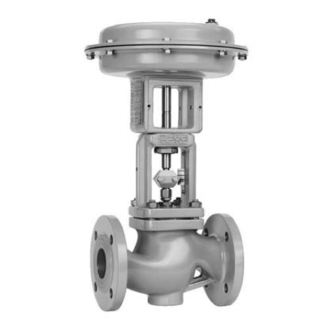
Type 3241-1 and Type 3241-7
Type 3241-1
Fig. 1 · Type 3241 Valve with Type 3271 Actuator and with Type 3277 Actuator
Mounting and
Operating Instructions
EB 8015 EN
Edition September 2009
Type 3241-7
Table of
Contents
Previous
Page
Next
Page
1
2
3
4
5
Advertisement
Table of Contents
Need help?
Do you have a question about the 3241-7 and is the answer not in the manual?
Ask a question
Questions and answers
Related Manuals for Samson 3241-7
Control Unit Samson 3241 Mounting And Operating Instructions
In combination with an actuator/pneumatic actuator (64 pages)
Control Unit Samson 3241 Manual
Competence in functional safety (32 pages)
Control Unit Samson 3256 Mounting And Operating Instructions
In combination with an actuator, e.g. a type 3271 or type 3277 pneumatic actuator (84 pages)
Control Unit Samson 3241 Series Mounting And Operating Instructions
Valve din version in combination with an actuator, e.g. a type 3271 or type 3277 pneumatic actuator (86 pages)
Control Unit Samson EB 8015 EN Mounting And Operating Instructions
(102 pages)
Control Unit Samson 3248 Mounting And Operating Instructions
(60 pages)
Control Unit Samson 3248 Mounting And Operating Instructions
Ansi version (84 pages)
Control Unit Samson 3241-1 Mounting And Operating Instructions
Pneumatic control valves (25 pages)
Control Unit Samson 3244 Operating Instructions Manual
(52 pages)
Control Unit Samson 3244 Mounting And Operating Instructions
Din and ansi versions in combination with an actuator, e.g. a type 3271 or type 3277 pneumatic actuator (72 pages)
Control Unit Samson 3244 Mounting And Operating Instructions
Din and ansi versions (88 pages)
Control Unit Samson 3244-1 Mounting And Operating Instructions
Pneumatic control valves (20 pages)
Control Unit Samson 3249 Mounting And Operating Instructions
Aseptic angle valve (60 pages)
Control Unit Samson 3241-1-Gas Mounting And Operating Instructions
Automatic shut-off valves for gases, class d (80 pages)
Control Unit Samson 3241-1-Gas Mounting And Operating Instructions
Automatic shut-off valves for gases (56 pages)
Control Unit Samson 3246 Mounting And Operating Instructions
(96 pages)
This manual is also suitable for:
3241-1
Table of Contents
Print
Rename the bookmark
Delete bookmark?
Delete from my manuals?
Login
Sign In
OR
Sign in with Facebook
Sign in with Google
Upload manual
Upload from disk
Upload from URL


Need help?
Do you have a question about the 3241-7 and is the answer not in the manual?
Questions and answers