Table of Contents
Advertisement
Quick Links
EB 8048 EN
Translation of original instructions
Ball body version
Special version with packing
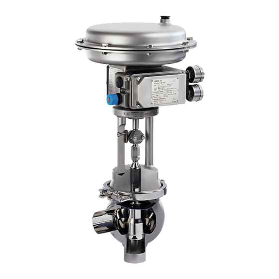
Type 3249 Valves with Type 3277 Actuator and integral positioner
Type 3249 Aseptic Angle Valve
In combination with an actuator,
e.g. a SAMSON Type 3271 or Type 3277 Pneumatic Actuator
Edition December 2019
Advertisement
Table of Contents

Related Manuals for Samson 3249


Summary of Contents for Samson 3249
- Page 1 EB 8048 EN Translation of original instructions Ball body version Special version with packing Type 3249 Valves with Type 3277 Actuator and integral positioner Type 3249 Aseptic Angle Valve In combination with an actuator, e.g. a SAMSON Type 3271 or Type 3277 Pneumatic Actuator Edition December 2019...
- Page 2 Note on these mounting and operating instructions These mounting and operating instructions assist you in mounting and operating the device safely. The instructions are binding for handling SAMSON devices. The images shown in these instructions are for illustration purposes only. The actual product may vary.
-
Page 3: Table Of Contents
Contents Safety instructions and measures ..............5 Notes on possible severe personal injury ............8 Notes on possible personal injury ..............8 Notes on possible property damage ..............10 Markings on the device ................12 Body inscription ...................12 Actuator nameplate ..................12 Material numbers ..................12 Label when an adjustable packing is installed ..........12 Design and principle of operation ..............14 Fail-safe positions ..................14 Versions ......................15... - Page 4 Disassembly ....................47 11.1 Removing the valve from the pipeline .............48 11.2 Removing the actuator from the valve ............48 Repairs .......................49 12.1 Returning devices to SAMSON ..............49 Disposal ......................50 Certificates ....................51 Annex......................54 15.1 Tightening torques, lubricants and tools ............54 15.2 Spare parts ....................54 15.3...
-
Page 5: Safety Instructions And Measures
In case operators intend to use the control valve in other applica- tions or conditions than specified, contact SAMSON. SAMSON does not assume any liability for damage resulting from the failure to use the de- vice for its intended purpose or for damage caused by external forces or any other external factors. - Page 6 (see associated actuator documentation). When the valve is combined with a SAMSON Type 3271 or Type 3277 Pneumatic Actuator, the valve moves to a certain fail- safe position upon supply air or control signal failure (see section 3.1). The fail-safe action of the actuator is the same as its direction of action and is specified on the nameplate of SAMSON actuators.
- Page 7 Safety instructions and measures Furthermore, the operator must ensure that operating personnel or third persons are not exposed to any danger. Hazards resulting from the special working conditions at the installation site of the valve must be identified in a risk assessment and prevented through the corresponding safety instruc- tions drawn up by the operator.
-
Page 8: Notes On Possible Severe Personal Injury
Safety instructions and measures 1.1 Notes on possible severe personal injury DANGER Risk of bursting in pressure equipment. Valves and pipelines are pressure equipment. Impermissible pressure or improper opening can lead to valve components bursting. Î Observe the maximum permissible pressure for valve and plant. Î... - Page 9 Risk of personal injury due to preloaded springs. Valves in combination with pneumatic actuators with preloaded springs are under tension. These control valves with SAMSON pneumatic actuators can be identified by the long bolts protruding from the bottom of the actuator.
-
Page 10: Notes On Possible Property Damage
Parts that are too loose may cause leakage. Î Observe the specified tightening torques (u AB 0100). Risk of valve damage due to the use of unsuitable tools. Certain tools are required to work on the valve. Î Only use tools approved by SAMSON (u AB 0100). EB 8048 EN... - Page 11 The lubricants to be used depend on the valve material. Unsuitable lubricants may cor- rode and damage the surface. Î Only use lubricants approved by SAMSON (u AB 0100). Risk of valve damage due to the use of unsuitable lubricants. The lubricants to be used depend on the valve material. Unsuitable lubricants may cor- rode and damage the surface.
-
Page 12: Markings On The Device
Markings on the device 2 Markings on the device 2.4 Label when an adjustable packing is installed 2.1 Body inscription An instructional label is affixed to the valve when an adjustable packing is installed (see The details on the valve version are lasered Fig. 2). - Page 13 2014/68/EU) Max. operating temperature °C/°F If applicable, EAC mark including month and year of production Flow coefficient: · C SAMSON material marking Characteristic: % = equal percentage · L = linear Seat/plug seal: ME: metal PK: soft PEEK seal PT: soft PTFE seal...
-
Page 14: Design And Principle Of Operation
(4.1, 4.2, 4.3). ation 3.1 Fail-safe positions The Type 3249 Angle Valve is preferably combined with either a Type 3271 Pneumat- The fail-safe position of the control valve up- ic Actuator or a Type 3277 Pneumatic Actu- on air supply or control signal failure de- ator with integral positioner attachment. -
Page 15: Versions
(e.g. 1.4435). so that the travel ranges match. See associ- Connections ated actuator documentation. The Type 3249 Valve can also be delivered As an alternative, the control valve can be with the following end connections: combined with a Type 3274 Electropneumat- −... - Page 16 Design and principle of operation Valve with Type 3271 Actuator (120 cm²) Valve with Type 3271 Actuator Special version with backup packing Type 3277 Actuator Fig. 4: Functional diagram EB 8048 EN...
-
Page 17: Additional Fittings
Design and principle of operation Legend for Fig. 4 Valve body Plug stem Plug Stem connector nut Spring Lock nut Packing Diaphragm Washer Grub screw Test connection Stem connector Valve bonnet Actuator Guide bushing Actuator stem Threaded bushing Ring nut Yoke Compression spring Screws Rolling diaphragm... -
Page 18: Technical Data
The noise emis- Type 3277 Actuator. sions depend on the valve version, plant fa- cilities and process medium. Conformity The Type 3249 Valve bears both the CE and EAC marks of conformity. · Application range DIN or ANSI valve versions for aseptic ap- plications in the food and pharmaceutical in- dustries. - Page 19 Design and principle of operation Dimensions and weights Table 1: Dimensions for Types 3249-1 and 3249-7 Control Valves · Dimensions in mm Table 1.1: Standard version (N) with ball body and special version (S) with backup packing Valve ½ ¾ 1¼ 1½ 2½...
- Page 20 Design and principle of operation Valve ½ ¾ 1¼ 1½ 2½ Clamp L3 (N) 60.3 60.3 60.3 88.9 88.9 88.9 88.9 95.3 1) 1) 1) 1) 1) 1) 1) 1) 1) 1) connections acc. Ød1 22.6 31.3 35.6 48.6 60.3 72.9 97.6 to ISO 2852...
- Page 21 Design and principle of operation Table 2: Weights for Type 3249 Valve · Weights in kg Valve ½ ¾ 1¼ 1½ 2½ Weight with weld- kg (approx.) (30 mm ing ends travel) Dimensional drawings ØD ØD ØD Ød2 Ød2 Ød2 Type 3249-7, ball body with Type 3249-1, ball body with...
-
Page 22: Shipment And On-Site Transport
2. Check the shipment for transportation Î Stay clear of suspended or moving damage. Report any damage to loads. SAMSON and the forwarding agent Î Close off and secure the transport paths. (refer to delivery note). 3. Determine the weight and dimensions of... -
Page 23: Transporting The Valve
Shipment and on-site transport Î Secure the valve against tipping over or turning. A swivel hoist can be screwed into SAMSON actuators with a female thread on the top diaphragm case in place of the WARNING eyebolt (see associated actuator Risk of injury due to incorrect lifting without documentation). -
Page 24: Lifting The Valve
− Secure slings against slipping. Fig. 5: Special version Fig. 6: Ball body − Make sure the slings can be removed of Type 3249 version of from the valve once it has been installed with Type 3249 Type 3271 with into the pipeline. -
Page 25: Storing The Valve
NOTICE Risk of valve damage due to improper stor- age. Î Observe the storage instructions. Fig. 7: Ball body version of Type 3249 with Î Avoid long storage times. Type 3271 Actuator fitted with a lifting Î Contact SAMSON in case of different... -
Page 26: Mounting
Elastomer, e.g. actuator diaphragm conditions and are intended as recommen- − To keep elastomers in shape and to pre- dations. Contact SAMSON if the lengths are vent cracking, do not bend them or hang significantly shorter than the recommended them up. - Page 27 Mounting Î Contact SAMSON if the mounting posi- vices. They ensure that any exhaust air that tion is not as specified above. forms can be vented to the atmosphere (to avoid excess pressure in the device). Further- Support or suspension...
-
Page 28: Preparation For Installation
Risk of valve damage due to the use of un- valve. suitable tools. Î Check any mounted pressure gauges to Î Only use tools approved by SAMSON make sure they function properly. (u AB 0100). Î When the valve and actuator are al-... -
Page 29: Mounting The Actuator Onto The Valve
Undo the clamp (5.6) and remove the documentation). entire valve-actuator extension from the valve body. Depending on the version, SAMSON control 6. Weld the valve body free of stress into valves are either delivered with the actuator the pipeline. already mounted on the valve or the valve and actuator are delivered separately. -
Page 30: Testing The Installed Valve
Mounting 5.4 Testing the installed valve cessories not fitted with noise-reducing fit- tings. Both can damage hearing. Î Wear hearing protection when working DANGER near the valve. Risk of bursting due to incorrect opening of pressurized equipment or components. Valves and pipelines are pressure equipment WARNING WARNING that may burst when handled incorrectly. -
Page 31: Leak Test
Mounting WARNING Risk of personal injury due to preloaded Our after-sales service can support you to springs. plan and perform a leak test for your plant. Actuators with preloaded springs are under tension. They can be identified by the long NOTICE bolts protruding from the bottom of the actu- Valve malfunction due to a leaking dia-... -
Page 32: Travel Motion
Mounting 5.4.4 Pressure test NOTICE Impaired valve functioning due to increased The plant operator is responsible for per- friction as a result of the threaded bushing forming the pressure test. being tightened too far. Î Make sure that the plug stem can still move smoothly after the threaded bush- Our after-sales service can support you to ing has been tightened. -
Page 33: Start-Up
Start-up 6 Start-up Î Wear hearing protection when working near the valve. The work described in this section is only to be performed by personnel qualified for the assignment accordingly. WARNING WARNING Crush hazard arising from actuator and WARNING plug stem moving. Risk of burn injuries due to hot or cold com- Î... - Page 34 Start-up Start-up/putting the regulator back into op- NOTICE eration Risk of impairment of aseptic or hygienic 1. Allow the valve to cool down or warm up service. to reach ambient temperature before In the version with backup packing, the test start-up when the ambient temperature connection is sealed by a stopper.
-
Page 35: Operation
Operation 7 Operation WARNING WARNING Immediately after completing start-up or put- Crush hazard arising from actuator and ting the valve back into operation (see sec- plug stem moving. tion 6), the valve is ready for use. Î Do not insert hands or finger into the yoke while the air supply is connected to the actuator. -
Page 36: Cip (Cleaning-In-Place)
Operation closed may lead to the diaphragm rupturing in plants with liquid media flowing through them. Î Only close the valve when the shut-off valves upstream and downstream of the valve are open. NOTICE Diaphragm damage due to uncontrolled pressure surges. Î... -
Page 37: Malfunctions
Malfunctions 8 Malfunctions 8.1 Troubleshooting Malfunction Possible reasons Recommended action Actuator and plug stem Actuator is blocked. Check attachment. does not move on Unblock the actuator. demand. WARNING! A blocked actuator or plug stem (e.g. due to seizing up after remaining in the same position for a long time) can suddenly start to move uncontrollably. -
Page 38: Emergency Action
Malfunctions Malfunction Possible reasons Recommended action The valve leaks to the Defective packing Replace packing (see section 9.4.2) or contact our atmosphere (fugitive after-sales service. emissions). Version with adjustable Adjust the packing (see information under Adjusting packing : packing not the packing in section 5.4). Contact our after-sales 1) tightened correctly service when it continues to leak. -
Page 39: Servicing
Servicing 9 Servicing Î Allow components and pipelines to cool down or heat up. The work described in this section is only to Î Wear protective clothing and safety be performed by personnel qualified for the gloves. assignment accordingly. The following documents are also necessary WARNING for servicing the valve: Risk of personal injury due to pressurized... - Page 40 Risk of valve damage due to the use of un- springs. suitable tools. Actuators with preloaded springs are under Î Only use tools approved by SAMSON tension. They can be identified by the long (u AB 0100). bolts protruding from the bottom of the actu- ator.
-
Page 41: Periodic Testing
Standard version 1. Put the control valve out of operation (see Note section 10). The control valve was checked by SAMSON 2. Remove the actuator from the valve. See before it left the factory. associated actuator documentation. − Certain test results certified by SAMSON 3. -
Page 42: Mounting The Valve After Service Work
Servicing 5. Lift the valve bonnet (5) together with the 5. Repeat this procedure several times to plug stem (6), plug (3) and diaphragm tighten the clamp as far as it will go. (6.3) off the body (1). 6. Screw the lock nut (6.2) and stem con- 6. -
Page 43: Service Work
5. Screw a new plug (3) onto the plug stem Instead of aligning the plug, the assembly (6) using a suitable tool. Observe tight- (consisting of plug stem, diaphragm and plug) can be ordered from SAMSON. ening torques. EB 8048 EN... -
Page 44: Replacing The Packing
9.5 Ordering spare parts and operating supplies Contact your nearest SAMSON subsidiary or SAMSON's After-sales Service for infor- mation on spare parts, lubricants and tools. Spare parts See Annex for details on spare parts. Lubricant See document u AB 0100 for details on... -
Page 45: Decommissioning
Decommissioning 10 Decommissioning WARNING The work described in this section is only to Risk of personal injury due to pressurized be performed by personnel qualified for the components and process medium escaping assignment accordingly. under pressure. Î Do not loosen the screw of the test con- nection while the valve is pressurized. - Page 46 Decommissioning (e.g. due to seizing up after remaining in Î Only close the valve when the shut-off the same position for a long time), valves upstream and downstream of the release any stored energy in the actuator valve are open. (e.g.
-
Page 47: Disassembly
Disassembly 11 Disassembly WARNING WARNING The work described in this section is only to Risk of personal injury due to residual pro- be performed by personnel qualified for the cess medium in the valve. assignment accordingly. While working on the valve, residual process medium can escape and, depending on its properties, may lead to personal injury, e.g. -
Page 48: Removing The Valve From The Pipeline
Disassembly 11.1 Removing the valve from the pipeline 1. Support the valve to hold it in place when separated from the pipeline (see section 4.3). 2. Cut the pipeline in front of the weld seam. Special version: Undo the pipe joint depending on the type of end connection used (see sec- tion 5.3.2). -
Page 49: Repairs
Î Do not perform any repair work on your outside of your shipment so that the own. documents are clearly visible. Î Contact SAMSON's After-sales Service 4. Send the shipment to the address given for repair work. on the RMA. -
Page 50: Disposal
Disposal 13 Disposal Î Observe local, national and internation- al refuse regulations. Î Do not dispose of components, lubricants and hazardous substances together with your household waste. EB 8048 EN... -
Page 51: Certificates
Certificates 14 Certificates The declaration of conformity in accordance with Pressure Equipment Directive 2014/68/ EU is provided on the following two pages: EB 8048 EN... - Page 52 BNP Paribas N° compte 0002200215245 • Banque 3000401857 Tél.: +33 (0)4 72 04 75 00 • Fax: +33 (0)4 72 04 75 75 • E-mail: samson@samson.fr • Internet: www.samson.fr IBAN FR7630004018570002200215245 • BIC (code SWIFT) BNPAFRPPVBE Société par actions simpifiée au capital de 10 000 000 € • Siège social : Vaulx-en-Velin Crédit Lyonnais...
- Page 53 BNP Paribas N° compte 0002200215245 • Banque 3000401857 Tél.: +33 (0)4 72 04 75 00 • Fax: +33 (0)4 72 04 75 75 • E-mail: samson@samson.fr • Internet: www.samson.fr IBAN FR7630004018570002200215245 • BIC (code SWIFT) BNPAFRPPVBE Société par actions simpifiée au capital de 10 000 000 € • Siège social : Vaulx-en-Velin Crédit Lyonnais...
-
Page 54: Annex
Annex 15 Annex 15.1 Tightening torques, lubri- cants and tools u AB 0100 for tools, tightening torques and lubricants 15.2 Spare parts Standard version for Type 3271 and Type 3277 Actuators Valve body Plug Bearing sleeve Valve bonnet Yoke Travel indicator scale Clamp Retaining plate Screw Plug stem Stem connector nut... - Page 55 Annex Special version with packing Valve body Plug Bearing sleeve Spring Packing Washer Test connection Seal for test connection Valve bonnet Threaded bushing Yoke Screws Travel indicator scale Retaining plate Screw Plug stem Stem connector nut Lock nut Diaphragm Grub screw EB 8048 EN...
-
Page 56: After-Sales Service
You can reach our after-sales service at aftersalesservice@samsongroup.com. Addresses of SAMSON AG and its subsid- iaries The addresses of SAMSON AG, its subsid- iaries, representatives and service facilities worldwide can be found on our website (www.samsongroup.com) or in all SAMSON product catalogs. - Page 57 EB 8048 EN...
- Page 58 EB 8048 EN...
- Page 59 EB 8048 EN...
- Page 60 EB 8048 EN SAMSON AKTIENGESELLSCHAFT Weismüllerstraße 3 · 60314 Frankfurt am Main, Germany Phone: +49 69 4009-0 · Fax: +49 69 4009-1507 samson@samsongroup.com · www.samsongroup.com...
Need help?
Do you have a question about the 3249 and is the answer not in the manual?
Questions and answers