Samson 3244 Mounting And Operating Instructions
Din and ansi versions
Hide thumbs
Also See for 3244:
- Operating instructions manual (52 pages) ,
- Mounting and operating instructions (72 pages)
Table of Contents
Advertisement
Quick Links
Advertisement
Table of Contents

Related Manuals for Samson 3244


Summary of Contents for Samson 3244
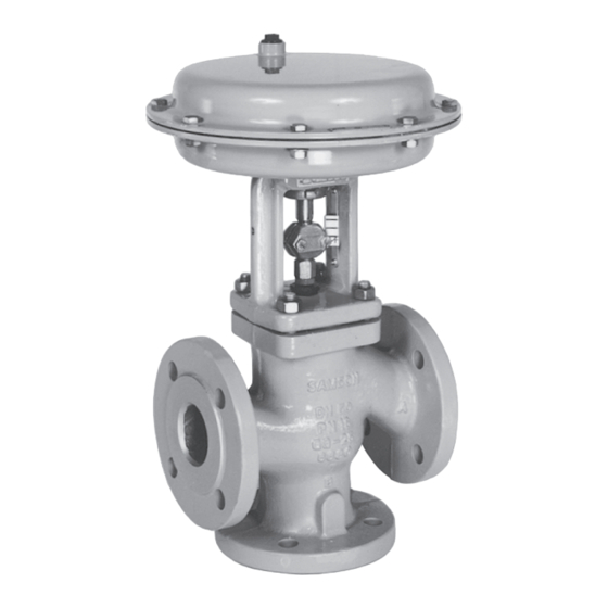
- Page 1 EB 8026 EN Translation of original instructions Type 3244 Valve with Type 3271 Actuator (left) and Type 3277 Actuator (right) Type 3244 Valve · DIN and ANSI versions In combination with an actuator, e.g. a Type 3271 or Type 3277 Pneumatic Actuator Edition April 2024...
- Page 2 Note on these mounting and operating instructions These mounting and operating instructions assist you in mounting and operating the device safely. The instructions are binding for handling SAMSON devices. The images shown in these instructions are for illustration purposes only. The actual product may vary.
-
Page 3: Table Of Contents
Contents Safety instructions and measures ..............1-1 Notes on possible severe personal injury ............1-5 Notes on possible personal injury ..............1-5 Notes on possible property damage .............1-7 Warnings on the device ................1-8 Markings on the device ................2-1 Valve nameplate ..................2-1 Actuator nameplate ..................2-2 Material identification number ..............2-2 Label when an adjustable packing is installed ..........2-3 Design and principle of operation ...............3-1... - Page 4 Removal ....................11-1 11.1 Removing the valve from the pipeline ............11-2 11.2 Removing the actuator from the valve ............11-2 Repairs ....................12-1 12.1 Returning devices to SAMSON ..............12-1 Disposal ....................13-1 Certificates ....................14-1 Appendix ....................15-1 15.1 Tightening torques, lubricants and tools ............15-1 15.2 Spare parts ....................15-1...
-
Page 5: Safety Instructions And Measures
SAMSON. SAMSON does not assume any liability for damage resulting from the failure to use the de- vice for its intended purpose or for damage caused by external forces or any other external factors. - Page 6 (see associated actuator documentation). When the valve is combined with a SAMSON Type 3271 or Type 3277 Pneumatic Actuator, the valve moves to a certain fail- safe position (see the 'Design and principle of operation' chapter) upon supply air or control signal failure.
- Page 7 Start-up and shutdown procedures fall within the scope of the operator's duties and, as such, are not part of these mounting and operating instructions. SAMSON is unable to make any statements about these procedures since the operative details (e.g. differential pressures and temperatures) vary in each individual case and are only known to the operator.
- Page 8 SAMSON > Environment, Social & Governance > Material Compliance > REACH If a device contains a substance listed as a substance of very high concern on the candi- date list of the REACH regulation, this is indicated on the SAMSON delivery note. EB 8026 EN...
-
Page 9: Notes On Possible Severe Personal Injury
Safety instructions and measures 1.1 Notes on possible severe personal injury DANGER Risk of bursting in pressure equipment. Valves and pipelines are pressure equipment. Excessive pressurization or improper opening can lead to valve components bursting. Î Observe the maximum permissible pressure for valve and plant. Î... - Page 10 Risk of personal injury due to preloaded springs. Valves in combination with pneumatic actuators with preloaded springs are under ten- sion. These control valves with SAMSON pneumatic actuators can be identified by the long bolts protruding from the bottom of the actuator.
-
Page 11: Notes On Possible Property Damage
Safety instructions and measures WARNING Risk of personal injury due to residual process medium in the valve. While working on the valve, residual medium can flow out of the valve and, depending on its properties, cause personal injury, e.g. (chemical) burns. Î... -
Page 12: Warnings On The Device
Risk of valve damage due to the use of unsuitable tools. Certain tools are required to work on the valve. Î Only use tools approved by SAMSON (u AB 0100). Risk of valve damage due to the use of unsuitable lubricants. The lubricants to be used depend on the valve material. Unsuitable lubricants may cor- rode and damage surfaces. -
Page 13: Markings On The Device
Only the 3: ST 3 · 1/PSA: ST 1 standard and inte- inscriptions relevant to the ordered grated in seat for PSA valve · Type 3244 Valve actually appear on the AC-1/AC-2/AC-3/AC-5: anti-cavitation trim, versions 1 to 5 nameplate. LK: perforated plug · LK1/LK2/LK3: perfo- rated plug with flow divider ST 1 to ST 3 ·... -
Page 14: Actuator Nameplate
The serial number enables you to view the device's current technical data as configured by SAMSON. The material number enables you to view the device's technical data as configured by SAMSON upon delivery of the device. To view these data, go to our website at u www.samsongroup.com >... -
Page 15: Label When An Adjustable Packing Is Installed
Markings on the device 2.4 Label when an adjustable packing is installed An instructional label is affixed to the valve when an adjustable packing is installed (see Fig. 2-3). Fig. 2-3: Label when an adjustable packing is installed EB 8026 EN... - Page 16 EB 8026 EN...
-
Page 17: Design And Principle Of Operation
The design of the mixing and divert- ing valves in sizes DN 15 to 25 (NPS ½ to In mixing valves, the process media to be 1) is identical. The Type 3244 Valve is pref- mixed enter at valve ports A and B. The erably combined with a SAMSON combined flow exits the valve at port AB (see Fig. 3-1). - Page 18 Design and principle of operation Fig. 3-2: Type 3244 Valve (as diverting valve) Fig. 3-1: Type 3244 Valve (as mixing valve) with Type 3271 Pneumatic Actuator A26/27 EB 8026 EN...
-
Page 19: Versions
The bypass ensures that the plant does dard valve version. not need to be shut down for service and re- Actuators pair work on the valve. In these instructions, the preferable combina- tion with a SAMSON Type 3271 or EB 8026 EN... -
Page 20: Valve Accessories
Refer to the instructions in the 'Installation' chapter. Conformity Test connection The Type 3244 Valve bears the CE, UKCA Versions with bellows seal fitted with a test and EAC mark of conformity. connection (G ) at the top flange allow the sealing ability of the bellows to be moni- tored. - Page 21 Table 3-1 to Table 3-4 provide an overview of the dimensions and weights of the standard version of Type 3244 Valve as well as the version with insulating section or bellows seal. The lengths and heights in the dimensional drawings are shown on page 3-6.
- Page 22 28.54 29.92 35.24 35.43 Dimensional drawings Standard version of Type 3244 Type 3244 with insulating section or bellows seal Table 3-4: Weights of Type 3244 Valve · Without actuator Valve ½ ¾ – 1½ 2½ – Standard version 15.5 17.5 28.7 37.5...
-
Page 23: Shipment And On-Site Transport
Shipment and on-site transport 4 Shipment and on-site trans- Î Leave the control valve in its transport container or on the pallet to transport it port on site. The work described in this chapter is only to Î Do not remove the protective caps from be performed by personnel appropriately the inlet and outlet until immediately be- qualified to carry out such tasks. -
Page 24: Transporting The Valve
Risk of personal injury due to the control A swivel hoist can be screwed into valve tipping over. SAMSON actuators with a female thread on Î Observe the valve's center of gravity. the top diaphragm case in place of the Î... -
Page 25: Lifting The Valve
Shipment and on-site transport − Protect the piping and any mounted Lifting instructions valve accessories against damage. − Use a hook with safety latch (see − Protect the control valve against moisture Fig. 4-1) to secure the slings from slip- and dirt. ping off the hook during lifting and transporting. -
Page 26: Storing The Valve
Î Observe the storage instructions. valve. Î Avoid long storage times. − For storage periods longer than 4 Î Contact SAMSON in case of different months, we recommend storing the con- storage conditions or longer storage trol valves in nominal sizes DN 150/ times. - Page 27 Shipment and on-site transport SAMSON's After-sales Service can provide more detailed storage instructions on re- quest. EB 8026 EN...
- Page 28 EB 8026 EN...
-
Page 29: Installation
Plant operators must ensure that, after instal- Î Observe the inlet and outlet lengths (see lation of the device, the operating personnel Table 5-1). Contact SAMSON if the can perform all necessary work safely and Table 5-1: Inlet and outlet lengths... - Page 30 − Valves in DN 100/NPS 4 and larger − Valves with insulating section for low temperatures below –10 °C (14 °F) Î Contact SAMSON if the mounting posi- tion is not as specified above. Support or suspension Note The plant engineering company is responsi-...
- Page 31 Installation Mixing service Diverting service Temperature control Q = constant Flow control Q = 0 to 100 % Fail-safe action: FA = "Actuator stem extends", FE = "Actuator stem retracts" In heating applications with FA, the heating medium (flow) is shut off in the fail-safe position, in cooling applications with FE, cooling is maintained in the fail-safe position.
-
Page 32: Preparation For Installation
Installation 5.2 Preparation for installation Before installation, make sure the following conditions are met: − The valve is clean. − The valve and all valve accessories (in- cluding piping) are not damaged. − The valve data on the nameplate (type ... -
Page 33: Mounting The Device
This is the largest of the three NOTICE V-shaped ports (see Fig. 5-3). Risk of valve damage due to the use of un- 2x small V-ports suitable tools. Î Only use tools approved by SAMSON (u AB 0100). 5.3.1 Mounting the actuator onto the valve WARNING Risk of personal injury due to preloaded springs. -
Page 34: Installing The Valve Into The Pipeline
Installation Î Before mounting the actuator, determine 6. Bolt the pipe to the valve free of stress. which V-shaped port is uncovered first 7. Attach a support or suspension on the when the plug is lifted out of the seat. valve, if necessary. - Page 35 Installation tions. Additionally, a loud noise may briefly WARNING occur through the sudden venting of the Risk of personal injury due to preloaded pneumatic actuator or pneumatic valve ac- springs. cessories not fitted with noise-reducing fit- Actuators with preloaded springs are under tings.
-
Page 36: Leakage
Installation To test the valve functioning before start-up NOTICE or putting back the valve into operation, per- Impaired valve functioning due to increased form the following tests: friction as a result of the threaded bushing being tightened too far. 5.5.1 Leakage Î... -
Page 37: Pressure Test
Installation 5.5.4 Pressure test The plant operator is responsible for per- forming the pressure test. Our after-sales service can support you to plan and perform a pressure test for your plant. During the pressure test, make sure the fol- lowing conditions are met: −... - Page 38 Installation 5-10 EB 8026 EN...
-
Page 39: Start-Up
Start-up 6 Start-up Î Wear hearing protection when working near the valve. The work described in this chapter is only to be performed by personnel appropriately qualified to carry out such tasks. WARNING WARNING Crush hazard arising from actuator and WARNING plug stem moving. - Page 40 Start-up Before start-up or putting the valve back into service, make sure the following conditions are met: − The valve is properly installed into the pipeline (see the 'Installation' chapter). − The leak and function tests have been completed successfully (see the 'Testing the installed valve' chapter).
-
Page 41: Operation
Operation 7 Operation Î Wear hearing protection when working near the valve. Immediately after completing start-up or put- ting the valve back into operation, the valve is ready for use. WARNING WARNING Crush hazard arising from actuator and WARNING plug stem moving. Risk of burn injuries due to hot or cold Î... -
Page 42: Normal Operation
Operation 7.1 Normal operation The handwheel of valves with actuators fitted with a handwheel must be in the neutral po- sition during normal operation. 7.2 Manual operation Valves with actuators fitted with a handwheel can be manually closed or opened in case of supply air failure. -
Page 43: Malfunctions
Malfunctions 8 Malfunctions Read hazard statements, warnings and caution notes in the 'Safety instructions and mea- sures' chapter. 8.1 Troubleshooting Malfunction Possible reasons Recommended action Actuator and plug stem Actuator is blocked. Put the control valve out of operation (see the does not move on 'Decommissioning' chapter) and remove the demand. -
Page 44: Emergency Action
Malfunctions Malfunction Possible reasons Recommended action The valve leaks to the Defective packing Replace packing (see the 'Servicing' chapter) or atmosphere (fugitive contact our after-sales service. emissions). Version with adjustable Tighten the packing correctly (see section 'Adjusting packing : packing not the packing' in the 'Installation' chapter >... -
Page 45: Servicing
Servicing 9 Servicing Î Allow components and pipelines to cool down or warm up to the ambient tem- The work described in this chapter is to be perature. performed only by personnel appropriately Î Wear protective clothing and safety qualified to carry out such tasks. gloves. - Page 46 Risk of valve damage due to the use of Risk of personal injury due to preloaded unsuitable tools. springs. Î Only use tools approved by SAMSON Actuators with preloaded springs are under (u AB 0100). tension. They can be identified by the long bolts protruding from the bottom of the actu- ator.
-
Page 47: Periodic Testing
Servicing 9.1 Periodic testing Note The control valve was checked by SAMSON Depending on the operating conditions, before delivery. check the valve at certain intervals to prevent − Certain test results certified by SAMSON possible failure before it can occur. Plant op-... - Page 48 Before unblocking the actuator, release any stored energy in the actuator (e.g. spring compression). See associated actuator documentation. SAMSON recommends the use of positioners with integrated diagnostic firmware for valves used for on/off service. The partial stroke test included in this software helps prevent a shut-off valve normally in its end position from seizing up or getting jammed.
- Page 49 Servicing External leakage: External leakage: Body gaskets at bellows seal/insulating Plug stem section/intermediate piece guide (packing) 2) External leakage: Body gaskets Test connection External leakage: Seat leakage: to monitor Metal bellows • Seat/body 2) bellows for • Plug/seat leakage External leakage: At pipeline joint 1)
-
Page 50: Service Work Preparations
'Installation' chap- disconnected again and locked. ter). SAMSON recommends removing the valve from the pipeline before performing any ser- vice work (see the 'Removing the valve from the pipeline' chapter). - Page 51 Stem connector clamps ing nut) 25 Plug stem extension 9 Stem connector nut 33 Nuts Fig. 9-2: Standard version of Type 3244 (as mixing valve) with Type 3271 Actuator (left) and Type 3244 (as diverting valve) in version with insulating section (right) EB 8026 EN...
-
Page 52: Replacing The Gasket
Servicing 9.4.1 Replacing the gasket Diverting valve ≥DN 32: firmly press the plug (5) into the top seat (4). Mixing valve: firmly press the plug (5) NOTICE into the bottom seat (141). Risk of control valve damage due to incor- Tighten the nuts gradually in a crisscross rect servicing. - Page 53 Servicing 5. Lift the flange (2) over the plug stem ex- 15. Firmly press the plug (5) into the bottom tension (25) off the insulating section seat (141). (21). Fasten down the insulating section (21) with the body nuts (14). Tighten the nuts 6.
- Page 54 Servicing 13. Push the two retaining washers (30) onto 5. Lift the insulating section (21) or bellows the plug stem (5). seal (22) together with the flange (2) and plug with plug stem (5) off the body (1). 14. Screw the plug stem with bellows (37) to the plug stem (5), making sure that the 6.
-
Page 55: Replacing The Packing
Servicing 15.1 15.2 Flange Plug with plug stem Threaded bushing (packing nut) Spring Washer Packing 15.1 Spacer ring with retaining ring 15.2 Seals Packing rings Fig. 9-3: Standard packing (left) and ADSEAL packing (right) 9.4.2 Replacing the packing Î To replace the packing in other valve ver- sions, contact our after-sales service. - Page 56 Servicing 4. Lift the flange (2) over the plug stem (5) 2. Slide the parts of the packing over the off the body (1). plug stem in the specified order: − Spring (11) 5. Pull the entire packing out of the packing −...
-
Page 57: Replacing The Seat And Plug
Servicing 8. Carefully place the flange (2) over the 4. Insert the red spacer ring (15.1) between plug stem extension (25) onto the insulat- the threaded bushing (8) and retaining ing section (21). ring. See Fig. 9-3. V-port plug: align the V-port plug, mak- 5. -
Page 58: Ordering Spare Parts And Operating Supplies
Servicing 9.5 Ordering spare parts and operating supplies Contact your nearest SAMSON subsidiary or SAMSON's After-sales Service for infor- mation on spare parts, lubricants and tools. Spare parts See Appendix for details on spare parts. Lubricant See document u AB 0100 for details on suitable lubricants. -
Page 59: Decommissioning
Decommissioning 10 Decommissioning WARNING The work described in this chapter is only to Risk of personal injury due to pressurized be performed by personnel appropriately components and process medium being qualified to carry out such tasks. discharged. Î Do not loosen the screw of the test con- nection while the valve is pressurized. - Page 60 Decommissioning Î Before unblocking the actuator and plug To decommission the control valve for service stem after they have become blocked work or to remove it from the pipeline, pro- (e.g. due to seizing up after remaining in ceed as follows: the same position for a long time), re- 1.
-
Page 61: Removal
Removal 11 Removal WARNING WARNING The work described in this chapter is only to Risk of personal injury due to residual be performed by personnel appropriately process medium in the valve. qualified to carry out such tasks. While working on the valve, residual me- dium can flow out of the valve and, depend- ing on its properties, cause personal injury, WARNING... -
Page 62: Removing The Valve From The Pipeline
Removal Before removing the valve, make sure the fol- lowing conditions are met: − The control valve is put out of operation (see the 'Decommissioning' chapter). 11.1 Removing the valve from the pipeline 1. Support the valve to hold it in place when separated from the pipeline (see the 'Shipment and on-site transport' chapter). -
Page 63: Repairs
Î Do not perform any repair work on your side of your shipment so that the docu- own. ments are clearly visible. Î Contact SAMSON's After-sales Service 4. Send the shipment to the address given for service and repair work. on the RMA. - Page 64 12-2 EB 8026 EN...
-
Page 65: Disposal
Disposal 13 Disposal SAMSON is a producer registered at the following European institution u https://www.ewrn.org/national- registers/national-registers. WEEE reg. no.: DE 62194439/ FR 02566 Î Observe local, national and internation- al refuse regulations. Î Do not dispose of components, lubricants and hazardous substances together with your household waste. - Page 66 13-2 EB 8026 EN...
-
Page 67: Certificates
Other optional certificates are available on see page 14-4 to 14-7 request. − Declaration of conformity in compliance with Machinery Directive 2006/42/EC for Types 3244-1 and 3244-7 Control Valves on page 14-8 − Declaration of incorporation in compli- ance with Machinery Directive 2006/42/EC for the Type 3244 Valve with other actuators other than Types 3271 and 3277 Actuators on... - Page 68 Modul A/Module A SAMSON erklärt in alleiniger Verantwortung für folgende Produkte:/For the following products, SAMSON hereby declares under its sole responsibility: Geräte/Devices Bauart/Series Typ/Type Ausführung/Version DIN, Gehäuse GG, DN 65-125, Gehäuse GGG, DN 50-80, Fluide G2, L1, L2 Durchgangsventil/Globe valve...
- Page 69 EB 8026 EN 14-3...
- Page 70 DC014 Module A / Modul A 2022-05 Par la présente, SAMSON REGULATION SAS déclare sous sa seule responsabilité pour les produits suivants : For the following products, SAMSON REGULATION SAS hereby declares under its sole responsibility: Appareils / Exécution / Matériel du corps / body...
- Page 71 Modul A Normes techniques appliquées / Technical standards applied : DIN EN 12516-2, DIN EN 12516-3, ASME B16.34, DIN-EN 60534-4, DIN-EN 1092-1 Fabricant / manufacturer : Samson Régulation SAS, 1, rue Jean Corona, FR-69120 VAULX-EN-VELIN Vaulx-en-Velin, le 23/05/22 Bruno Soulas Joséphine Signoles-Fontaine...
- Page 72 Module H / Modul H, N°/ Nr CE-0062-PED-H-SAM 001-23-FRA 2023-06 Par la présente, SAMSON REGULATION SAS déclare sous sa seule responsabilité pour les produits suivants : For the following products, SAMSON REGULATION SAS hereby declares under its sole responsibility: Appareils / Exécution /...
- Page 73 The manufacturer’s quality management system is monitored by the following notified body: Bureau Veritas Services SAS N°/Nr 0062, 8 Cours du Triangle, 92800 PUTEAUX - LA DEFENSE Fabricant / manufacturer : Samson Régulation SAS, 1, rue Jean Corona, FR-69120 VAULX-EN-VELIN Vaulx-en-Velin, le 19/06/23 Bruno Soulas Joséphine Signoles-Fontaine...
- Page 74 14-8 EB 8026 EN...
- Page 75 EB 8026 EN 14-9...
- Page 76 14-10 EB 8026 EN...
- Page 77 Machinery components can be mounted onto the above specified final ma- chinery if they comply with the specifications and properties defined by SAMSON Manual H 02 “Ap- propriate Machinery Components for SAMSON Pneumatic Control Valves with a Declaration of Con- formity of Final Machinery”.
- Page 78 For the following product: Type 3244 Pneumatic Control Valve We certify that the Type 3244 Pneumatic Control Valves are partly completed machinery as defined in the in Directive 2008 No. 1597 Supply of Machinery (Safety) Regulations 2008 and that the safety requirements stip- ulated in Annex I, 1.1.2, 1.1.3, 1.1.5, 1.3.2, 1.3.4 and 1.3.7 are observed.
- Page 79 Operating temperature: -29° C ≤ T ≤425° C. SAMSON REGULATION S.A. SAMSON REGULATION S.A. Bruno Soulas Joséphine Signoles-Fontaine Head of Administration QSE Manager SAMSON REGULATION S.A. · 1, rue Jean Corona · 69511 Vaulx-en-Velin, France · samson@samson.fr EB 8026 EN 14-13...
- Page 80 14-14 EB 8026 EN...
-
Page 81: Appendix
Appendix 15 Appendix 15.1 Tightening torques, lubricants and tools u AB 0100 for tools, tightening torques and lubricants 15.2 Spare parts Body Guide bushing (bellows seal) Flange Plug stem extension Top seat Label (bellows seal or insulating sec- tion) Plug (with plug stem) Retaining washers Guide bushing (flange) Bolt... - Page 82 15-2 EB 8026 EN...
- Page 83 EB 8026 EN 15-3...
-
Page 84: After-Sales Service
Addresses of SAMSON AG and its subsid- Importer iaries SAMSON Controls Ltd The addresses of SAMSON AG, its subsid- Perrywood Business Park iaries, representatives and service facilities Honeycrock Lane worldwide can be found on our website Redhill, Surrey RH1 5JQ (www.samsongroup.com) or in all SAMSON Phone: +44 1737 766391... - Page 88 EB 8026 EN SAMSON AKTIENGESELLSCHAFT Weismüllerstraße 3 · 60314 Frankfurt am Main, Germany Phone: +49 69 4009-0 · Fax: +49 69 4009-1507 samson@samsongroup.com · www.samsongroup.com...
Need help?
Do you have a question about the 3244 and is the answer not in the manual?
Questions and answers