Samson 3241 Series Mounting And Operating Instructions
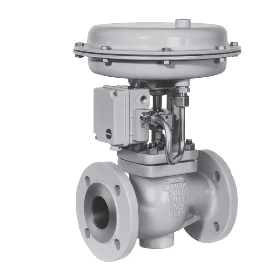
Valve din version in combination with an actuator, e.g. a type 3271 or type 3277 pneumatic actuator
Hide thumbs
Also See for 3241 Series:
- Mounting and operating instructions (64 pages) ,
- Manual (32 pages) ,
- Mounting and operating instructions (84 pages)
Table of Contents
Advertisement
Quick Links
Advertisement
Table of Contents

Related Manuals for Samson 3241 Series


Summary of Contents for Samson 3241 Series
- Page 1 EB 8015 EN Translation of original instructions Type 3241 Valve with Type 3271 Actuator (left) and Type 3277 Actuator (right) Type 3241 Valve · DIN version In combination with an actuator, e.g. a Type 3271 or Type 3277 Pneumatic Actuator Edition May 2020...
- Page 2 Note on these mounting and operating instructions These mounting and operating instructions assist you in mounting and operating the device safely. The instructions are binding for handling SAMSON devices. The images shown in these instructions are for illustration purposes only. The actual product may vary.
-
Page 3: Table Of Contents
Contents Safety instructions and measures ..............1-1 Notes on possible severe personal injury ............1-4 Notes on possible personal injury ..............1-5 Notes on possible property damage .............1-7 Warnings on the device ................1-8 Markings on the device ................2-1 Valve nameplate ..................2-1 Actuator nameplate ..................2-2 Material numbers ..................2-2 Label when an adjustable packing is installed ..........2-2 Design and principle of operation ...............3-1... - Page 4 Removal ....................11-1 11.1 Removing the valve from the pipeline ............11-2 11.2 Removing the actuator from the valve ............11-2 Repairs ....................12-1 12.1 Returning devices to SAMSON ..............12-1 Disposal ....................13-1 Certificates ....................14-1 Annex......................15-1 15.1 Tightening torques, lubricants and tools ............15-1 15.2 Spare parts ....................15-1 15.3...
-
Page 5: Safety Instructions And Measures
SAMSON. SAMSON does not assume any liability for damage resulting from the failure to use the de- vice for its intended purpose or for damage caused by external forces or any other external factors. - Page 6 (see associated actuator documentation). When the valve is combined with a SAMSON Type 3271 or Type 3277 Pneumatic Actuator, the valve moves to a certain fail- safe position (see the 'Design and principle of operation' section) upon supply air or control signal failure.
- Page 7 Start-up and shutdown procedures fall within the scope of the operator's duties and, as such, are not part of these mounting and operating instructions. SAMSON is unable to make any statements about these processes since the operative details (e.g. differential pressures and temperatures) vary in each individual case and are only known to the operator.
-
Page 8: Notes On Possible Severe Personal Injury
− u AB 0100 for tools, tightening torques and lubricant − For oxygen service: Manual u H 01 − Manual u H 02: Appropriate Machinery Components for SAMSON Pneumatic Control Valves with a Declaration of Conformity of Final Machinery 1.1 Notes on possible severe personal injury DANGER Risk of bursting in pressure equipment. -
Page 9: Notes On Possible Personal Injury
Safety instructions and measures 1.2 Notes on possible personal injury WARNING Risk of burn injuries due to hot or cold components and pipelines. Depending on the process medium, valve components and pipelines may get very hot or cold and cause burn injuries. Î... - Page 10 Risk of personal injury due to preloaded springs. Valves in combination with pneumatic actuators with preloaded springs are under ten- sion. These control valves with SAMSON pneumatic actuators can be identified by the long bolts protruding from the bottom of the actuator.
-
Page 11: Notes On Possible Property Damage
Risk of valve damage due to the use of unsuitable tools. Certain tools are required to work on the valve. Î Only use tools approved by SAMSON (u AB 0100). Risk of valve damage due to the use of unsuitable lubricants. The lubricants to be used depend on the valve material. Unsuitable lubricants may cor- rode and damage surfaces. -
Page 12: Warnings On The Device
Safety instructions and measures 1.4 Warnings on the device Warning Meaning of the warning Location on the device Warning against moving parts There is a risk of injury to hands or fingers through the stroking movement of the actuator and plug stem if they are inserted into the yoke while the air supply is con- nected to the actuator. -
Page 13: Markings On The Device
Markings on the device 2 Markings on the device Note Fig. 2-1 and the inscription table list all pos- 2.1 Valve nameplate sible characteristics and options that may appear on a valve nameplate. Only the in- scriptions relevant to the ordered Type 3241 Valve actually appear on the nameplate. -
Page 14: Actuator Nameplate
Markings on the device 2.4 Label when an adjustable The valve nameplate (80) in valve sizes DN 15 to 150 is affixed to the flange packing is installed (Fig. 2-2). The valve nameplate in valve sizes DN 200 and larger is located on the yoke An instructional label is affixed to the valve (Fig. 2-3). -
Page 15: Design And Principle Of Operation
The fail-safe position of the control valve up- globe valve. This valve is preferably com- on air supply or control signal failure de- bined with a SAMSON Type 3271 or pends on the actuator used (see associated Type 3277 Pneumatic Actuator. It can also actuator documentation). - Page 16 Design and principle of operation Fig. 3-1: Type 3241-1 Control Valve with Type 3271 Pneumatic Actuator, body up to DN 150 Body Flange Yoke Seat Plug (with plug stem) Threaded bushing (packing nut) Stem connector nut Lock nut Spring Nuts Packing Body gasket Travel indicator scale Castellated nut Actuator Actuator stem...
-
Page 17: Versions
3.1 Versions Actuators In these instructions, the preferable combina- With insulating section/bellows seal tion with a SAMSON Type 3271 or The modular design allows an insulating sec- Type 3277 Pneumatic Actuator is described. tion or bellows seal to be fitted to the stan- The pneumatic actuator (with or without dard valve version. -
Page 18: Additional Fittings
For operating conditions that require in- Strainers creased safety (e.g. in cases where the valve We recommend installing a SAMSON is freely accessible to untrained staff), a safe- strainer upstream of the valve. It prevents sol- ty guard must be installed to rule out a crush... -
Page 19: Technical Data
Design and principle of operation 3.4 Technical data Noise emissions SAMSON is unable to make general state- The nameplates on the valve and actuator ments about noise emissions. The noise emis- provide information on the control valve ver- sions depend on the valve version, plant fa- sion. - Page 20 Design and principle of operation Dimensions and weights Table 3-1 to Table 3-3 provide an overview of the dimensions and weights of the standard version of Type 3241 Valve. Table 3-4 and Table 3-5 list the dimensions and weights for the Type 3241 Valve with insulating section or bellows seal. Dimensions in mm ·...
- Page 21 Design and principle of operation Table 3-3: Weights for Type 3241 Valve 250 (cast Valve DN 15 80 100 125 150 200 250 300 iron) Weight kg 6 108 430 858 920 Dimensional drawings Type 3241 · DN 15 to 150 Type 3241 · DN 200 to 300 EB 8015 EN...
- Page 22 Design and principle of operation Table 3-4: Dimensions and weights for the Type 3241 Valve with insulating section or bellows seal up to DN 150 Valve size DN 15 80 100 125 150 Insulating section or 636 645 672 ≤750 cm² bellows seal Long 877 886 913 1) Insulating...
- Page 23 Refer to the following data sheets for more dimensions and weights: u T 8015 for valves with bellows seal, insulating section or heating jacket The associated actuator documentation applies to actuators, e.g. for SAMSON pneumatic actuators: u T 8310-1 for Type 3271 or Type 3277 Pneumatic Actuators up to 750 cm² actuator area u T 8310-2 for Type 3271 Actuator with 1000 cm²...
- Page 24 3-10 EB 8015 EN...
-
Page 25: Shipment And On-Site Transport
2. Check the shipment for transportation Î Stay clear of suspended or moving damage. Report any damage to loads. SAMSON and the forwarding agent Î Close off and secure the transport paths. (refer to delivery note). 3. Determine the weight and dimensions of... -
Page 26: Transporting The Valve
Risk of personal injury due to the control A swivel hoist can be screwed into valve tipping over. SAMSON actuators with a female thread on Î Observe the valve's center of gravity. the top diaphragm case in place of the Î... -
Page 27: Lifting The Valve
Shipment and on-site transport − Protect the piping and any mounted Note valve accessories against damage. Contact our after-sales service for the trans- − Protect the control valve against moisture portation temperatures of other valve ver- and dirt. sions. − The permissible transportation tempera- ture of standard control valves is –20 to 4.3.2 Lifting the valve... - Page 28 Shipment and on-site transport Lifting instructions 3. Carefully lift the control valve. Check whether the lifting equipment and acces- − Use a hook with safety latch (see sories can bear the weight. Fig. 4-1) to secure the slings from slip- ping off the hook during lifting and 4.
-
Page 29: Storing The Valve
Elastomer, e.g. actuator diaphragm Î Avoid long storage times. − To keep elastomers in shape and to pre- Î Contact SAMSON in case of different vent cracking, do not bend them or hang storage conditions or long storage peri- them up. - Page 30 EB 8015 EN...
-
Page 31: Installation
–10 °C Plant operators must ensure that, after instal- lation of the device, the operating personnel Î Contact SAMSON if the mounting posi- can perform all necessary work safely and tion is not as specified above. -
Page 32: Preparation For Installation
Installation 5.2 Preparation for installation Vent plugs Vent plugs are screwed into the exhaust air Before installation, make sure the following ports of pneumatic and electropneumatic de- conditions are met: vices. They ensure that any exhaust air that − The valve is clean. forms can be vented to the atmosphere (to avoid excess pressure in the device). -
Page 33: Installing The Device
Î Flush the pipelines. Risk of valve damage due to the use of unsuitable tools. Note Î Only use tools approved by SAMSON The plant operator is responsible for clean- (u AB 0100). ing the pipelines in the plant. Î For steam applications, dry the pipelines. -
Page 34: Mounting The External Anti-Rotation Fixture
The valve must plied lubricant. be closed beforehand. Î Do not apply any lubricant to the stem For SAMSON Type 3271 and Type 3277 (9), plug stem or the threads of the Actuators with Type 3273 Hand-operated clamps (301). - Page 35 Installation − The anti-rotation fixture does not get stuck on the yoke and can move free- ly in the direction of travel. 14. Extend the actuator stem again and mount the stem connector clamps. Plug stem Legend Yoke Screws Hanger Travel indicator scale Screws Castellated nut...
- Page 36 Installation Plug stem Legend Stem Lubricant Gleitmo 1763 V Clamps Screws Washers Slider disks Fig. 5-2: Overview of anti-rotation fixture assembly EB 8015 EN...
- Page 37 Installation Table 5-3: Mounting dimensions for Types 3271 and 3277 Pneumatic Actuators · See Fig. 5-3 for dimensional drawing Trav- Actuator Actuator preloading Dimension when the valve is closed [mm] [cm²] [mm] [mm] DN 200 to 250/NPS 8 to 10 up to seat bore 200 · Standard version 1000 1400-60 87.5...
-
Page 38: Mounting The Actuator Onto The Valve
Installation Fig. 5-3: Dimensional drawing with mounting dimensions for Types 3271 and 3277 Pneumatic Actuators 5.3.2 Mounting the actuator tension. They can be identified by the long bolts protruding from the bottom of the actu- onto the valve ator. Î Before starting any work on the actuator, WARNING relieve the compression from the pre- Risk of personal injury due to preloaded... - Page 39 Installation Depending on the version, SAMSON control Mounting dimensions for valves up to valves are either delivered with the actuator DN 150 already mounted on the valve or the valve The following mounting dimensions apply to and actuator are delivered separately. When Type 3241 Valves, NPS <8/DN <200:...
-
Page 40: Installing The Valve Into The Pipeline
Installation b) Aligning the travel indicator 'Lifting the valve' section). Observe the flow direction through the valve. The ar- scale row on the valve indicates the direction of flow. After mounting the actuator, the travel indi- cator scale must be aligned. To do so, align 5. - Page 41 Installation Î Drain the process medium from all the Î Do not impede the movement of the actu- plant sections concerned as well as the ator and plug stem by inserting objects valve. into the yoke. Î Before unblocking the actuator and plug stem after they have become blocked WARNING (e.g.
-
Page 42: Leak Test
Installation To test the valve functioning before start-up NOTICE or putting back the valve into operation, per- Impaired valve functioning due to increased form the following tests: friction as a result of the threaded bushing being tightened too far. 5.4.1 Leak test Î... -
Page 43: Travel Motion
Installation 5.4.2 Travel motion The movement of the actuator stem must be linear and smooth. Î Apply the maximum and minimum con- trol signals to check the end positions of the valve while observing the movement of the actuator stem. Î... - Page 44 5-14 EB 8015 EN...
-
Page 45: Start-Up
Start-up 6 Start-up Î Wear hearing protection when working near the valve. The work described in this section is only to be performed by personnel appropriately qualified to carry out such tasks. WARNING WARNING Crush hazard arising from actuator and WARNING plug stem moving. - Page 46 Start-up Before start-up or putting the valve back into service, make sure the following conditions are met: − The valve is properly installed into the pipeline (see the 'Installation' section). − The leak and function tests have been completed successfully (see the 'Testing the installed valve' section).
-
Page 47: Operation
Operation 7 Operation WARNING WARNING Immediately after completing start-up or put- Crush hazard arising from actuator and ting the valve back into operation, the valve plug stem moving. is ready for use. Î Do not insert hands or finger into the yoke while the air supply is connected to the actuator. -
Page 48: Normal Operation
Operation 7.1 Normal operation The handwheel of valves with actuators fitted with a handwheel must be in the neutral po- sition during normal operation. 7.2 Manual operation Valves with actuators fitted with a handwheel can be manually closed or opened in case of supply air failure. -
Page 49: Malfunctions
Malfunctions 8 Malfunctions Read hazard statements, warnings and caution notes in the 'Safety instructions and mea- sures' section. 8.1 Troubleshooting Malfunction Possible reasons Recommended action Actuator and plug stem Actuator is blocked. Check attachment. does not move on Remove the blockage. demand. -
Page 50: Emergency Action
Malfunctions Malfunction Possible reasons Recommended action The valve leaks to the Defective packing Replace packing (see the 'Servicing' section) or con- atmosphere (fugitive tact our after-sales service. emissions). Version with adjustable Adjust the packing (see information under packing : packing not 'Adjusting the packing' in the 'Testing the installed 1) tightened correctly... -
Page 51: Servicing
Servicing 9 Servicing Î Allow components and pipelines to cool down or heat up. The work described in this section is only to Î Wear protective clothing and safety be performed by personnel appropriately gloves. qualified to carry out such tasks. The following documents are also necessary WARNING for servicing the valve:... - Page 52 Risk of valve damage due to the use of tension. They can be identified by the long unsuitable tools. bolts protruding from the bottom of the actu- Î Only use tools approved by SAMSON ator. (u AB 0100). Î Before starting any work on the actuator,...
-
Page 53: Periodic Testing
Servicing 9.1 Periodic testing Note The control valve was checked by SAMSON Depending on the operating conditions, before it left the factory. check the valve at certain intervals to prevent − Certain test results certified by SAMSON a possible failure before it can occur. Opera-... - Page 54 Servicing Inspection and testing Action to be taken in the event of a negative result: Check the pipe connections and gaskets Check the bolted joint (tightening torque). on the valve and actuator for leakage. Replace the gasket on the flanged joint as described in sec- tion 9.4.
- Page 55 Servicing Body Guide bushing Flange/valve bonnet Plug stem extension Seat Retaining washers Plug (with plug stem) Bolt Threaded bushing (packing nut) Stem connector nut Travel indicator scale Lock nut Actuator Spring Actuator stem Body nut Ring nut Packing Stem connector clamps Packing rings Body gasket Insulating section...
-
Page 56: Preparing The Valve For Service Work
Servicing 9.2 Preparing the valve for 9.3 Mounting the valve after service work service work 1. Lay out the necessary material and tools 1. Mount actuator. See associated actuator to have them ready for the service work. documentation. 2. Put the control valve out of operation (see 2. -
Page 57: Replacing The Gasket
Servicing 9.4.1 Replacing the gasket b) Version with insulating section or bellows seal NOTICE 1. Undo the body nuts (14) gradually in a Risk of control valve damage due to incor- crisscross pattern. rect servicing. 2. Lift the insulating section (21) with valve Î... -
Page 58: Replacing The Packing
Servicing 15.1 15.2 Valve bonnet Plug with plug stem Threaded bushing (packing nut) Spring Washer Packing 15.1 Spacer ring with retaining ring 15.2 Seals Packing rings Fig. 9-2: Standard packing (left) and ADSEAL packing (right) 9.4.2 Replacing the packing Î To replace the packing in other valve ver- sions, contact our after-sales service. - Page 59 Servicing 5. Pull the plug with plug stem (5) out of the − Spring (11) flange (2). − Washer (12) − Packing rings (16) 6. Pull the entire packing out of the packing chamber using a suitable tool. 3. Slide the seals (15.2) over the plug stem. Insert the wire of the red spacer ring 7.
-
Page 60: Replacing The Seat And Plug
Servicing 8. Carefully lift the valve bonnet (2) over the 4. Insert the red spacer ring (15.1) between plug stem extension (25) onto the insulat- the threaded bushing (8) and retaining ing section (21). ring. See Fig. 9-2. Version with V-port plug: place the valve 5. - Page 61 Servicing a) Standard version ing a suitable tool. Observe the proper sequence (see Fig. 9-2). 1. Undo the body nuts (14) gradually in a 15. Firmly press the plug (5) into the seat (4). crisscross pattern. Fasten down the flange (2) with the body 2.
-
Page 62: Ordering Spare Parts And Operating Supplies
16. Hold the new plug with plug stem (5) sta- Contact your nearest SAMSON subsidiary tionary. Place on the insulating section or SAMSON's After-sales Service for infor- (21). Screw the plug stem extension (25) mation on spare parts, lubricants and tools. -
Page 63: Decommissioning
Decommissioning 10 Decommissioning WARNING The work described in this section is only to Risk of personal injury due to pressurized be performed by personnel appropriately components and process medium being dis- qualified to carry out such tasks. charged. Î Do not loosen the screw of the test con- nection while the valve is pressurized. - Page 64 Decommissioning (e.g. due to seizing up after remaining in 3. Disconnect and lock the pneumatic air the same position for a long time), re- supply to depressurize the actuator. lease any stored energy in the actuator 4. Release any stored energy. (e.g.
-
Page 65: Removal
Removal 11 Removal WARNING WARNING The work described in this section is only to Risk of personal injury due to residual pro- be performed by personnel appropriately cess medium in the valve. qualified to carry out such tasks. While working on the valve, residual me- dium can flow out of the valve and, depend- ing on its properties, cause personal injury, WARNING... -
Page 66: Removing The Valve From The Pipeline
Removal 11.1 Removing the valve from the pipeline a) Version with flanges 1. Support the valve to hold it in place when separated from the pipeline (see the 'Shipment and on-site transport' sec- tion). 2. Unbolt the flange joint. 3. Remove the valve from the pipeline (see the 'Shipment and on-site transport' sec- tion). -
Page 67: Repairs
7. Send the shipment to the address given Î Do not perform any repair work on your on the RMA. own. Î Contact SAMSON's After-sales Service Note for repair work. Further information on returned devices and how they are handled can be found at 12.1 Returning devices to... - Page 68 12-2 EB 8015 EN...
-
Page 69: Disposal
Disposal 13 Disposal Î Observe local, national and internation- al refuse regulations. Î Do not dispose of components, lubricants and hazardous substances together with your household waste. EB 8015 EN 13-1... - Page 70 13-2 EB 8015 EN...
-
Page 71: Certificates
Certificates 14 Certificates These declarations of conformity are includ- ed on the next pages: − Declaration of conformity in compliance with Pressure Equipment Directive 2014/68/EU: − Country of origin: Germany, see page 14-2 to 14-4 − Country of origin: France, see page 14-5 to 14-8 −... - Page 72 Modul A/Module A SAMSON erklärt in alleiniger Verantwortung für folgende Produkte:/For the following products, SAMSON hereby declares under its sole responsibility: Geräte/Devices Bauart/Series Typ/Type Ausführung/Version DIN, Gehäuse GG, DN 65-125, Gehäuse GGG, DN 50-80, Fluide G2, L1, L2 Durchgangsventil/Globe valve...
- Page 73 EB 8015 EN 14-3...
- Page 74 14-4 EB 8015 EN...
- Page 75 BNP Paribas N° compte 0002200215245 • Banque 3000401857 Tél.: +33 (0)4 72 04 75 00 • Fax: +33 (0)4 72 04 75 75 • E-mail: samson@samson.fr • Internet: www.samson.fr IBAN FR7630004018570002200215245 • BIC (code SWIFT) BNPAFRPPVBE Société par actions simpifiée au capital de 10 000 000 € • Siège social : Vaulx-en-Velin Crédit Lyonnais...
- Page 76 BNP Paribas N° compte 0002200215245 • Banque 3000401857 Tél.: +33 (0)4 72 04 75 00 • Fax: +33 (0)4 72 04 75 75 • E-mail: samson@samson.fr • Internet: www.samson.fr IBAN FR7630004018570002200215245 • BIC (code SWIFT) BNPAFRPPVBE Société par actions simpifiée au capital de 10 000 000 € • Siège social : Vaulx-en-Velin Crédit Lyonnais...
- Page 77 BNP Paribas N° compte 0002200215245 • Banque 3000401857 Tél.: +33 (0)4 72 04 75 00 • Fax: +33 (0)4 72 04 75 75 • E-mail: samson@samson.fr • Internet: www.samson.fr IBAN FR7630004018570002200215245 • BIC (code SWIFT) BNPAFRPPVBE Société par actions simpifiée au capital de 10 000 000 € • Siège social : Vaulx-en-Velin Crédit Lyonnais...
- Page 78 BNP Paribas N° compte 0002200215245 • Banque 3000401857 Tél.: +33 (0)4 72 04 75 00 • Fax: +33 (0)4 72 04 75 75 • E-mail: samson@samson.fr • Internet: www.samson.fr IBAN FR7630004018570002200215245 • BIC (code SWIFT) BNPAFRPPVBE Société par actions simpifiée au capital de 10 000 000 € • Siège social : Vaulx-en-Velin Crédit Lyonnais...
- Page 79 EB 8015 EN 14-9...
- Page 80 14-10 EB 8015 EN...
-
Page 81: Annex
Annex 15 Annex 15.1 Tightening torques, lubricants and tools u AB 0100 for tools, tightening torques and lubricants 15.2 Spare parts Body Screw plug with seal Flange/valve bonnet Ring/ring nut 1) Yoke Packing ring 1) Seat Gasket 1) Plug (with plug stem) Support 1) Guide bushing (flange) - Page 82 DN 15…150 NPS ½…6 14 33 30 33 15-2 EB 8015 EN...
- Page 83 80 81 DN 200…300 80 81 83 84 NPS 8…12 (DN 250, DN 300) (10", 12") 13 91 EB 8015 EN 15-3...
-
Page 84: After-Sales Service
You can reach our after-sales service at aftersalesservice@samsongroup.com. Addresses of SAMSON AG and its subsid- iaries The addresses of SAMSON AG, its subsid- iaries, representatives and service facilities worldwide can be found on our website (www.samsongroup.com) or in all SAMSON product catalogs. - Page 86 EB 8015 EN SAMSON AKTIENGESELLSCHAFT Weismüllerstraße 3 · 60314 Frankfurt am Main, Germany Phone: +49 69 4009-0 · Fax: +49 69 4009-1507 samson@samsongroup.com · www.samsongroup.com...
Need help?
Do you have a question about the 3241 Series and is the answer not in the manual?
Questions and answers