
Related Manuals for Samson 3256


Summary of Contents for Samson 3256
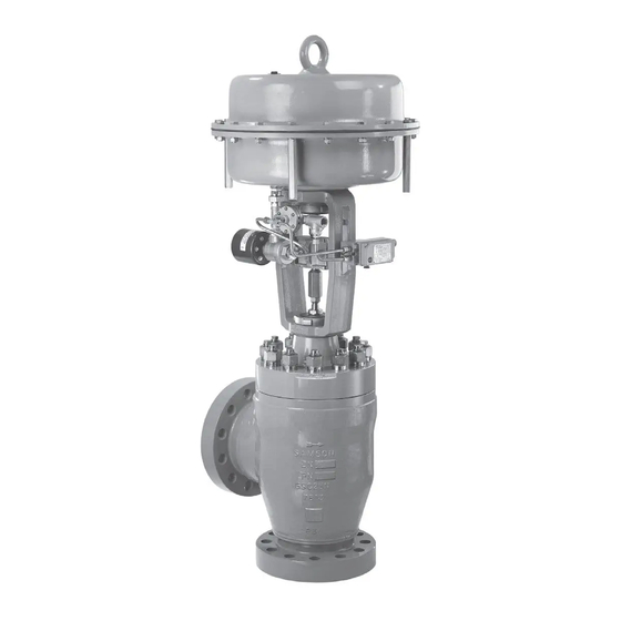
- Page 1 EB 8065 EN Translation of original instructions Type 3256 Valve with Type 3271 Actuator Type 3256 Valve · DIN version In combination with an actuator, e.g. a Type 3271 or Type 3277 Pneumatic Actuator Edition May 2020...
- Page 2 Note on these mounting and operating instructions These mounting and operating instructions assist you in mounting and operating the device safely. The instructions are binding for handling SAMSON devices. The images shown in these instructions are for illustration purposes only. The actual product may vary.
-
Page 3: Table Of Contents
Contents Safety instructions and measures ..............1-1 Notes on possible severe personal injury ............1-4 Notes on possible personal injury ..............1-4 Notes on possible property damage .............1-6 Warnings on the device ................1-8 Markings on the device ................2-1 Valve nameplate ..................2-1 Actuator nameplate ..................2-2 Material numbers ..................2-2 Label when an adjustable packing is installed ..........2-2 Design and principle of operation ...............3-1... - Page 4 Removal ....................11-1 11.1 Removing the valve from the pipeline ............11-2 11.2 Removing the actuator from the valve ............11-2 Repairs ....................12-1 12.1 Returning devices to SAMSON ..............12-1 Disposal ....................13-1 Certificates ....................14-1 Annex......................15-1 15.1 Tightening torques, lubricants and tools ............15-1 15.2 Spare parts ....................15-1 15.3...
-
Page 5: Safety Instructions And Measures
SAMSON. SAMSON does not assume any liability for damage resulting from the failure to use the de- vice for its intended purpose or for damage caused by external forces or any other external factors. - Page 6 (see associated actuator documentation). When the valve is combined with a SAMSON Type 3271 or Type 3277 Pneumatic Actuator, the valve moves to a certain fail- safe position (see the 'Design and principle of operation' section) upon supply air or control signal failure.
- Page 7 Start-up and shutdown procedures fall within the scope of the operator's duties and, as such, are not part of these mounting and operating instructions. SAMSON is unable to make any statements about these procedures since the operative details (e.g. differential pressures and temperatures) vary in each individual case and are only known to the operator.
-
Page 8: Notes On Possible Severe Personal Injury
− Mounting and operating instructions for mounted valve accessories (positioner, solenoid valve etc.) − u AB 0100 for tools and tightening torques − Manual u H 02: Appropriate Machinery Components for SAMSON Pneumatic Control Valves with a Declaration of Conformity of Final Machinery 1.1 Notes on possible severe personal injury DANGER Risk of bursting in pressure equipment. - Page 9 Risk of personal injury due to preloaded springs. Valves in combination with pneumatic actuators with preloaded springs are under ten- sion. These control valves with SAMSON pneumatic actuators can be identified by the long bolts protruding from the bottom of the actuator.
-
Page 10: Notes On Possible Property Damage
Safety instructions and measures WARNING Risk of personal injury due to residual process medium in the valve. While working on the valve, residual medium can flow out of the valve and, depending on its properties, cause personal injury, e.g. (chemical) burns. Î... - Page 11 Risk of valve damage due to the use of unsuitable tools. Certain tools are required to work on the valve. Î Only use tools approved by SAMSON (u AB 0100). Risk of valve damage due to the use of unsuitable lubricants. The lubricants to be used depend on the valve material. Unsuitable lubricants may cor- rode and damage surfaces.
-
Page 12: Warnings On The Device
Safety instructions and measures 1.4 Warnings on the device Warning Meaning of the warning Location on the device Warning against moving parts There is a risk of injury to hands or fingers through the stroking movement of the actuator and plug stem if they are inserted into the yoke while the air supply is con- nected to the actuator. -
Page 13: Markings On The Device
2.1 Valve nameplate possible characteristics and options that may appear on a valve nameplate. Only the inscriptions relevant to the ordered Type 3256 Valve actually appear on the nameplate. Fig. 2-1: Inscriptions on the valve nameplate Item Inscription meaning Item Inscription meaning... -
Page 14: Actuator Nameplate
Markings on the device The nameplate (80) is affixed to the yoke of the valve (see Fig. 2-2). Fig. 2-3: Label when an adjustable packing is installed Fig. 2-2: Location of the nameplate 2.2 Actuator nameplate See associated actuator documentation. 2.3 Material numbers The seat and plug of the valves have an item number written on them. -
Page 15: Design And Principle Of Operation
3.1 Fail-safe position ation The fail-safe position of the control valve up- on air supply or control signal failure de- The Type 3256 Angle Valve is preferably pends on the actuator used (see associated combined with a SAMSON Type 3271 or actuator documentation). - Page 16 Stem connector nut Lock nut Body nut Packing A26/27 Body gasket Travel indicator scale Castellated nut Diaphragm Actuator stem Ring nut Spring Vent plug A26/27 Stem connector clamps Signal pressure connection Fig. 3-1: Type 3256 Angle Valve with Type 3271 Pneumatic Actuator EB 8065 EN...
-
Page 17: Versions
Actuators Insulation In these instructions, the preferable combina- Control valves can be insulated to reduce tion with a SAMSON Type 3271 or heat energy transfer. Type 3277 Pneumatic Actuator is described. Refer to the instructions in the 'Installation' The pneumatic actuator (with or without section. -
Page 18: Accessories
Safety guard Noise emissions For operating conditions that require in- SAMSON is unable to make general state- creased safety (e.g. in cases where the valve ments about noise emissions. The noise emis- is freely accessible to untrained staff), a safe-... - Page 19 Design and principle of operation Table 3-1: Technical data for Type 3256 Cast stainless Material Cast steel 1.0619 Cast steel 1.7357 steel 1.4408 15 to 200 to 15 to 200 to 15 to 200 to Valve size 16 to 16 to...
- Page 20 Dimensions and weights Table 3-2 and Table 3-3 provide an overview of the dimensions and weights of the standard version of Type 3256 Valve. The lengths and heights in the dimensional drawing are shown on page 3-7. Dimensions in mm · Weights in kg Table 3-2: Dimensions for Type 3256 Valve...
- Page 21 Refer to the following data sheets for more dimensions and weights: u T 8065 for valves with bellows seal, insulating section or heating jacket The associated actuator documentation applies to actuators, e.g. for SAMSON pneumatic actuators: u T 8310-1 for Type 3271 or Type 3277 Pneumatic Actuators up to 750 cm² actuator area u T 8310-2 for Type 3271 Actuator with 1000 cm²...
- Page 22 EB 8065 EN...
-
Page 23: Shipment And On-Site Transport
2. Check the shipment for transportation Î Stay clear of suspended or moving damage. Report any damage to loads. SAMSON and the forwarding agent Î Close off and secure the transport paths. (refer to delivery note). 3. Determine the weight and dimensions of... -
Page 24: Transporting The Valve
Risk of personal injury due to the control A swivel hoist can be screwed into valve tipping over. SAMSON actuators with a female thread on Î Observe the valve's center of gravity. the top diaphragm case in place of the Î... -
Page 25: Lifting The Valve
Shipment and on-site transport − Protect the piping and any mounted − Make sure that the additional sling be- valve accessories against damage. tween the lifting eyelet and rigging equipment (hook, shackle etc.) does not − Protect the control valve against moisture bear any load when lifting valves larger and dirt. - Page 26 Shipment and on-site transport Î Contact SAMSON in case of different − To keep elastomers in shape and to pre- storage conditions or long storage peri- vent cracking, do not bend them or hang ods. them up. − We recommend a storage temperature of 15 °C for elastomers.
-
Page 27: Installation
–10 °C Plant operators must ensure that, after instal- lation of the device, the operating personnel Î Contact SAMSON if the mounting posi- can perform all necessary work safely and tion is not as specified above. easily access the device from the work posi- Support or suspension tion. - Page 28 Installation Table 5-1: Inlet and outlet lengths Flow rate Inlet length Outlet length b x DN State of process medium Valve conditions Inlet length a Outlet length b Inlet Outlet Ma ≤ 0.3 0.3 ≤ Ma ≤ 0.7 Ma ≤ 0.3 1) 0.3 ≤ Ma ≤ 0.7 1) Vapor Saturated steam (percentage of con- densate > 5 %) Free of cavitation/w < 10 m/s Cavitation producing...
-
Page 29: Preparation For Installation
Installation 5.2 Preparation for installation Î Flush the pipelines. Before installation, make sure the following Note conditions are met: The plant operator is responsible for clean- − The valve is clean. ing the pipelines in the plant. − The valve and all valve accessories (in- cluding piping) are not damaged. -
Page 30: Mounting The External Anti-Rotation Fixture
Risk of valve damage due to the use of un- cording to Table 5-4. suitable tools. 6. Use a soft-faced hammer or lever press Î Only use tools approved by SAMSON to press the slider disks (309) with their (u AB 0100). beveled part first (without using any lu- bricant) into the recesses of the clamps 5.3.1... - Page 31 Installation Table 5-2: Tightening torques on each side (see detailed view Y in Fig. 5-2). Screw size Tightening torque – The anti-rotation fixture does not get [Nm] stuck on the yoke and can move free- ly in the direction of travel. 14.
- Page 32 Installation Plug stem Legend Stem Lubricant Gleitmo 1763 V Clamps Screws Washers Slider disks Fig. 5-2: Overview of anti-rotation fixture assembly in the standard version EB 8065 EN...
- Page 33 Installation b) Special version in valve sizes 8. Thread the stem (9) upwards until the head of the stem rests on the extended DN 50 to 100 actuator stem. See Fig. 5-3 and Fig. 5-4 9. Retract the actuator stem to relieve the stem (9).
- Page 34 Installation Legend Yoke Screws Hanger Plug stem Travel indicator scale Castellated nut Warning label Holder Screws Washers Fig. 5-3: Overview of yoke assembly with travel indicator scale in the special version EB 8065 EN...
- Page 35 Installation Plug stem Legend Stem Lubricant Gleitmo 1763 V Clamps Screws Washers Slider disks Fig. 5-4: Overview of anti-rotation fixture assembly in the special version EB 8065 EN...
- Page 36 Installation Table 5-4: Mounting dimensions for Types 3271 and 3277 Pneumatic Actuators · See Fig. 5-5 for dimensional drawing Trav- Actuator Actuator preloading Dimension when the valve is closed [mm] [cm²] [mm] [mm] DN 50 to 100/NPS 2 to 4 · Special version 3.75 –...
- Page 37 Installation Trav- Actuator Actuator preloading Dimension when the valve is closed [mm] [cm²] [mm] [mm] DN 200 to 250/NPS 8 to 10 up to seat bore 200 · Standard version 1000 1400-60 87.5 1400-120 2800 5600 DN 250/NPS 10, seat bore 250 and DN 300 to 500/NPS 12 to 20 · Standard version 1000 1400-60 1400-120...
- Page 38 Installation Ball bearings (standard version only) Fig. 5-5: Dimensional drawing with mounting dimensions for Types 3271 and 3277 Pneumatic Actuators 5-12 EB 8065 EN...
-
Page 39: Mounting The Actuator Onto The Valve
First to release the flow when the documentation). plug is lifted out of the seat. Fig. 5-6: V-port plug Depending on the version, SAMSON control valves are either delivered with the actuator a) Mounting the actuator already mounted on the valve or the valve and actuator are delivered separately. -
Page 40: Installing The Valve Into The Pipeline
Installation 5.3.3 Installing the valve into 2. Completely retract the actuator stem to protect the plug from sparks during weld- the pipeline ing. "Stem extends" direction of action: apply a signal pressure to the actuator. NOTICE "Stem retracts" direction of action: the Premature wear and leakage due to insuffi- valve is open without any signal pressure cient support or suspension. - Page 41 Installation WARNING WARNING WARNING Risk of hearing loss or deafness due to loud Risk of personal injury due to exhaust air noise. being vented. Noise emission (e.g. cavitation or flashing) While the valve is operating, the actuator, may occur during operation caused by the for example, may vent during closed-loop process medium and the operating condi- operation or when the valve opens or closes.
-
Page 42: Leak Test
Installation To test the valve functioning before start-up NOTICE or putting back the valve into operation, per- Impaired valve functioning due to increased form the following tests: friction as a result of the threaded bushing being tightened too far. 5.4.1 Leak test Î... -
Page 43: Travel Motion
Installation 5.4.2 Travel motion The movement of the actuator stem must be linear and smooth. Î Apply the maximum and minimum con- trol signals to check the end positions of the valve while observing the movement of the actuator stem. Î... - Page 44 5-18 EB 8065 EN...
-
Page 45: Start-Up
Start-up 6 Start-up Î Wear hearing protection when working near the valve. The work described in this section is only to be performed by personnel appropriately qualified to carry out such tasks. WARNING WARNING Crush hazard arising from actuator and WARNING plug stem moving. - Page 46 Start-up Before start-up or putting the valve back into service, make sure the following conditions are met: − The valve is properly installed into the pipeline (see the 'Installation' section). − The leak and function tests have been completed successfully (see the 'Testing the installed valve' section).
-
Page 47: Operation
Operation 7 Operation WARNING WARNING Immediately after completing start-up or put- Crush hazard arising from actuator and ting the valve back into operation, the valve plug stem moving. is ready for use. Î Do not insert hands or finger into the yoke while the air supply is connected to the actuator. -
Page 48: Normal Operation
Operation 7.1 Normal operation The handwheel of valves with actuators fitted with a handwheel must be in the neutral po- sition during normal operation. 7.2 Manual operation Valves with actuators fitted with a handwheel can be manually closed or opened in case of supply air failure. -
Page 49: Malfunctions
Malfunctions 8 Malfunctions Read hazard statements, warnings and caution notes in the 'Safety instructions and mea- sures' section. 8.1 Troubleshooting Malfunction Possible reasons Recommended action Actuator and plug stem Actuator is blocked. Check attachment. does not move on de- Remove the blockage. mand. -
Page 50: Emergency Action
Malfunctions Malfunction Possible reasons Recommended action The valve leaks to the Defective packing Replace packing (see the 'Servicing' section) or atmosphere (fugitive contact our after-sales service. emissions). Version with adjustable Adjust the packing (see information under packing : packing not 'Adjusting the packing' in the 'Testing the 1) tightened correctly... -
Page 51: Servicing
Servicing 9 Servicing Î Allow components and pipelines to cool down or heat up. The work described in this section is only to Î Wear protective clothing and safety be performed by personnel appropriately gloves. qualified to carry out such tasks. The following documents are also necessary WARNING for servicing the valve:... - Page 52 Risk of valve damage due to the use of tension. They can be identified by the long unsuitable tools. bolts protruding from the bottom of the actu- Î Only use tools approved by SAMSON ator. (u AB 0100). Î Before starting any work on the actuator,...
-
Page 53: Periodic Testing
Servicing 9.1 Periodic testing Note The control valve was checked by SAMSON Depending on the operating conditions, before it left the factory. check the valve at certain intervals to prevent − Certain test results certified by SAMSON a possible failure before it can occur. Opera-... - Page 54 Servicing Inspection and testing Action to be taken in the event of a negative result: Check the test connection and bellows Put the control valve out of operation (see the 'Decommis- seal (if used) for external leakage. sioning' section). To repair the bellows section, contact our WARNING! Risk of personal injury due after-sales service (see the 'Repairs' section).
-
Page 55: Preparing The Valve For Service Work
Servicing 9.2 Preparing the valve for 9.3 Mounting the valve after service work service work 1. Lay out the necessary material and tools 1. Mount actuator. See associated actuator to have them ready for the service work. documentation. 2. Put the control valve out of operation (see 2. -
Page 56: Replacing The Packing
Servicing Î To replace the gasket in other valve 3. Remove the gasket (17). Carefully clean versions, contact our after-sales service. the sealing faces in the valve body (1) and on the insulating section (21) or bel- lows seal (22). a) Standard version 4. - Page 57 Vent plug Plug (with plug stem) Insulating section A26/27 Stem connector clamps Threaded bushing Travel indicator scale Signal pressure (packing nut) connection Castellated nut Stem connector nut Diaphragm Fig. 9-1: Standard version of Type 3256 Valve with Type 3271 Actuator EB 8065 EN...
- Page 58 (2) onto the valve body, making sure that the largest V-shaped port of the V-port plug faces toward the valve outlet. See 'Mounting the actuator onto the valve' in the 'Installation' section. Fig. 9-2: Type 3256 with insulating section EB 8065 EN...
- Page 59 Servicing b) Version with insulating 12. Carefully slide the packing parts over the plug stem into the packing chamber us- section ing a suitable tool. Observe the proper sequence (see Fig. 9-3). Standard packing (PTFE) 13. Firmly press the plug (5) into the seat (4). 1.
- Page 60 Servicing 8 Threaded bushing 11 Spring 12 Washer 16 Packing ring 19 Spacer Fig. 9-3: Standard packing: DN 15 to 40 (left) and DN 50 to 100 (right) 12. Carefully slide the packing parts over the 16. Loosely screw the lock nut (10) and stem connector nut (9) onto the plug stem.
- Page 61 Servicing 15.1 15.1 15.2 15.2 8 Threaded bushing 15.2 Seal 11 Spring 16 Packing ring 12 Washer 18 Bushing 15 Packing (entire) 19 Spacer 15.1 Spacer ring with retaining ring Fig. 9-4: ADSEAL packing: DN 15 to 40 (left) and DN 50 to 100 (right) 4.
-
Page 62: Replacing The Seat And Plug
Servicing 9.4.3 Replacing the seat and a) Standard version plug 1. Unscrew the castellated nut (92) and lift the yoke (3) off the bonnet (2). NOTICE 2. Undo the body nuts (14) gradually in a Risk of control valve damage due to crisscross pattern. - Page 63 Servicing 15. Place the bonnet (2) together with the 4. Replace the gasket as described in sec- plug stem and plug (5) onto the body tion 9.4.1. (1). 5. Unthread the stem connector nut (9) and Version with V-port plug: place the bon- lock nut (10) from the plug stem (5).
-
Page 64: Ordering Spare Parts And Operating Supplies
(9) onto the plug stem. 9.5 Ordering spare parts and operating supplies Contact your nearest SAMSON subsidiary or SAMSON's After-sales Service for infor- mation on spare parts, lubricants and tools. Spare parts See Annex for details on spare parts. -
Page 65: Decommissioning
Decommissioning 10 Decommissioning WARNING The work described in this section is only to Risk of personal injury due to pressurized be performed by personnel appropriately components and process medium being qualified to carry out such tasks. discharged. Î Do not loosen the screw of the test con- nection while the valve is pressurized. - Page 66 Decommissioning (e.g. due to seizing up after remaining in 3. Disconnect and lock the pneumatic air the same position for a long time), re- supply to depressurize the actuator. lease any stored energy in the actuator 4. Release any stored energy. (e.g.
-
Page 67: Removal
Removal 11 Removal WARNING WARNING The work described in this section is only to Risk of personal injury due to residual be performed by personnel appropriately process medium in the valve. qualified to carry out such tasks. While working on the valve, residual medium can flow out of the valve and, depending on its properties, cause personal WARNING... -
Page 68: Removing The Valve From The Pipeline
Removal 11.1 Removing the valve from the pipeline a) Version with flanges 1. Support the valve to hold it in place when separated from the pipeline (see the 'Shipment and on-site transport' sec- tion). 2. Unbolt the flange joint. 3. Remove the valve from the pipeline (see the 'Shipment and on-site transport' sec- tion). -
Page 69: Repairs
Î Do not perform any repair work on your side of your shipment so that the docu- own. ments are clearly visible. Î Contact SAMSON's After-sales Service 4. Send the shipment to the address given for repair work. on the RMA. - Page 70 12-2 EB 8065 EN...
-
Page 71: Disposal
Disposal 13 Disposal Î Observe local, national and internation- al refuse regulations. Î Do not dispose of components, lubricants and hazardous substances together with your household waste. EB 8065 EN 13-1... - Page 72 13-2 EB 8065 EN...
-
Page 73: Certificates
Pressure Equipment Directive 2014/68/EU on page 14-2 − Declaration of conformity in compliance with Machinery Directive 2006/42/EC for Types 3256-1 and 3256-7 Control Valves on page 14-3 − Declaration of incorporation in compli- ance with Machinery Directive 2006/42/EC for the Type 3256 Valve with other actuators other than Types 3271 and 3277 Actuators on... - Page 74 14-2 EB 8065 EN...
- Page 75 EB 8065 EN 14-3...
- Page 76 14-4 EB 8065 EN...
-
Page 77: Annex
Annex 15 Annex 15.1 Tightening torques, lubricants and tools u AB 0100 for tools, tightening torques and lubricants 15.2 Spare parts 1 Body 44 Ring/ring nut 1) 2 Bonnet 45 Packing ring 1) 3 Yoke 46 Gasket 1) 4 Seat 47 Support 1) 5 Plug 48 Hex screw... - Page 78 15-2 EB 8065 EN...
-
Page 79: After-Sales Service
You can reach our after-sales service at aftersalesservice@samsongroup.com. Addresses of SAMSON AG and its subsid- iaries The addresses of SAMSON AG, its subsid- iaries, representatives and service facilities worldwide can be found on our website (www.samsongroup.com) or in all SAMSON product catalogs. - Page 80 15-4 EB 8065 EN...
- Page 84 EB 8065 EN SAMSON AKTIENGESELLSCHAFT Weismüllerstraße 3 · 60314 Frankfurt am Main, Germany Phone: +49 69 4009-0 · Fax: +49 69 4009-1507 samson@samsongroup.com · www.samsongroup.com...
Need help?
Do you have a question about the 3256 and is the answer not in the manual?
Questions and answers