Tektronix Keithley DMM7510 User Manual
7 1/5 digit graphical sampling multimeter
Hide thumbs
Also See for Keithley DMM7510:
- Quick start manual (26 pages) ,
- Applications manual (65 pages)

Related Manuals for Tektronix Keithley DMM7510


Summary of Contents for Tektronix Keithley DMM7510
- Page 1 tek.com/keithley Model DMM7510 7½ Digit Graphical Sampling Multimeter User’s Manual DMM7510-900-01 Rev. C / September 2019 *PDMM7510-900-01C* DMM7510-900-01C...
- Page 2 Model DMM7510 7½ Digit Multimeter User's Manual...
- Page 3 © 2019, Keithley Instruments, LLC Cleveland, Ohio, U.S.A. All rights reserved. Any unauthorized reproduction, photocopy, or use of the information herein, in whole or in part, without the prior written approval of Keithley Instruments, LLC, is strictly prohibited. These are the original instructions in English. ®...
- Page 4 Safety precautions The following safety precautions should be observed before using this product and any associated instrumentation. Although some instruments and accessories would normally be used with nonhazardous voltages, there are situations where hazardous conditions may be present. This product is intended for use by personnel who recognize shock hazards and are familiar with the safety precautions required to avoid possible injury.
- Page 5 For safety, instruments and accessories must be used in accordance with the operating instructions. If the instruments or accessories are used in a manner not specified in the operating instructions, the protection provided by the equipment may be impaired. Do not exceed the maximum signal levels of the instruments and accessories. Maximum signal levels are defined in the specifications and operating information and shown on the instrument panels, test fixture panels, and switching cards.
-
Page 6: Table Of Contents
Table of contents Introduction ......................1-1 Welcome ..........................1-1 Introduction to this manual ....................1-1 Extended warranty ....................... 1-2 Contact information ......................1-2 Organization of manual sections ..................1-2 Application examples ......................1-3 Front-panel overview ....................2-1 Front-panel overview ......................2-1 Instrument power ......................... - Page 7 Table of contents Model DMM7510 7½ Digit Multimeter User's Manual USB communications ......................3-8 Connect a computer to the DMM7510 using USB ..............3-8 Communicate with the instrument ..................... 3-9 Using the web interface...................... 3-13 Connect to the instrument web interface ................. 3-13 LAN troubleshooting suggestions ....................
- Page 8 Model DMM7510 7½ Digit Multimeter User's Manual Table of contents Using SCPI commands ......................7-3 Using TSP ..........................7-4 Test results..........................7-6 Grading and binning resistors ................8-1 Introduction .......................... 8-1 Instrument connections ......................8-2 Resistor grading and binning test ..................8-2 Trigger-model template: GradeBinning ..................
-
Page 9: Introduction
Section 1 Introduction In this section: Welcome .................. 1-1 Introduction to this manual ............1-1 Extended warranty ..............1-2 Contact information ..............1-2 Organization of manual sections ..........1-2 Application examples ............... 1-3 Welcome Thank you for choosing a Keithley Instruments product. The Keithley Instruments Model DMM7510 is a 7½... -
Page 10: Extended Warranty
Section 1: Introduction Model DMM7510 7½ Digit Multimeter User's Manual Extended warranty Additional years of warranty coverage are available on many products. These valuable contracts protect you from unbudgeted service expenses and provide additional years of protection at a fraction of the price of a repair. -
Page 11: Application Examples
Model DMM7510 7½ Digit Multimeter User's Manual Section 1: Introduction Application examples This manual provides application examples that show you how to perform tests from the front panel and over a remote interface. The applications include: • Making basic front-panel measurements (on page 4-1): Shows the basic measure functionality using a single DMM7510 and a two-terminal device under test. -
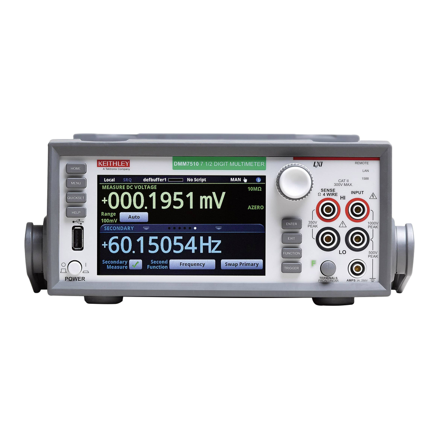
Page 12: Front-Panel Overview
Section 2 Front-panel overview In this section: Front-panel overview ..............2-1 Instrument power ..............2-3 Touchscreen display ..............2-4 Swipe screens ................2-8 Menu overview ............... 2-12 Front-panel overview The front panel of the DMM7510 is shown below. Descriptions of the controls on the front panel follow the figure. - Page 13 Section 2: Front-panel overview Model DMM7510 7½ Digit Multimeter User's Manual Opens a menu of preconfigured setups, including Voltage QUICKSET key Waveform, Interval Measure, Current Waveform, and External Scan. Also allows you to choose measure functions and adjust performance for better resolution or speed. Opens help for the area or item that is selected on the display.
-
Page 14: Instrument Power
Model DMM7510 7½ Digit Multimeter User's Manual Section 2: Front-panel overview Use the INPUT HI and INPUT LO terminals for all measurements INPUT terminals except current. AMPS Use the AMPS connection with the INPUT LO terminal to measure ≤3 A DC or AC current. -
Page 15: Connect The Power Cord
Section 2: Front-panel overview Model DMM7510 7½ Digit Multimeter User's Manual Connect the power cord To connect the power cord: 1. Make sure that the front-panel POWER switch is in the off (O) position. 2. Connect the female end of the supplied power cord to the AC receptacle on the rear panel. 3. -
Page 16: Select Items On The Touchscreen
Model DMM7510 7½ Digit Multimeter User's Manual Section 2: Front-panel overview access additional interactive screens by pressing the front-panel MENU, QUICKSET, and FUNCTION keys. Do not use sharp metal objects, such as tweezers or screwdrivers, or pointed objects, such as pens or pencils, to touch the touchscreen. It is strongly recommended that you use only fingers to operate the instrument. -
Page 17: Enter Information
Section 2: Front-panel overview Model DMM7510 7½ Digit Multimeter User's Manual Enter information Some of the menu options open a keypad or keyboard that you can use to enter information. For example, if you are setting the name of a buffer from the front panel, you see the keyboard shown in the following figure. -
Page 18: Adjust The Backlight Brightness And Dimmer
Model DMM7510 7½ Digit Multimeter User's Manual Section 2: Front-panel overview Adjust the backlight brightness and dimmer You can adjust the brightness of the DMM7510 touchscreen display and buttons from the front panel or over a remote interface. You can also set the backlight to dim after a specified time has passed with no front-panel activity (available from the front-panel display only). -
Page 19: Swipe Screens
Section 2: Front-panel overview Model DMM7510 7½ Digit Multimeter User's Manual Swipe screens The DMM7510 touchscreen display has multiple screens that you can access by swiping left or right on the lower half of the display. The options available in the swipe screens are described in the following topics. -
Page 20: Functions Swipe Screen
Model DMM7510 7½ Digit Multimeter User's Manual Section 2: Front-panel overview FUNCTIONS swipe screen The FUNCTIONS swipe screen highlights the selected measure function and allows you to select a different function. Figure 6: FUNCTIONS swipe screen SETTINGS swipe screen The SETTINGS swipe screen gives you front-panel access to some instrument settings for the selected measure function. -
Page 21: Statistics Swipe Screen
Section 2: Front-panel overview Model DMM7510 7½ Digit Multimeter User's Manual STATISTICS swipe screen The STATISTICS swipe screen contains information about the readings in the active reading buffer. When the reading buffer is configured to fill continuously and overwrite old data with new data, the buffer statistics include the data that was overwritten. -
Page 22: User Swipe Screen
Model DMM7510 7½ Digit Multimeter User's Manual Section 2: Front-panel overview Figure 9: SECONDARY swipe screen Depending on the selected functions, a relay may click when the instrument switches between the measurement types. Leaving secondary measurements on for extended periods may shorten the life of the relays. -
Page 23: Graph Swipe Screen
Section 2: Front-panel overview Model DMM7510 7½ Digit Multimeter User's Manual GRAPH swipe screen The GRAPH swipe screen shows a graphical representation of the readings in the presently selected reading buffer. Figure 11: GRAPH swipe screen To view the graph on the full screen and to access graph settings, select the graph icon on the right side of the swipe screen header. -
Page 24: Measure Menu
Model DMM7510 7½ Digit Multimeter User's Manual Section 2: Front-panel overview Measure menu The Measure menus allow you to select, configure, and perform measure operations from the front panel. The QuickSet menu allows you to change the function and adjust performance. You can also access the QuickSet menu by pressing the QUICKSET key on the front panel. -
Page 25: Trigger Menu
Section 2: Front-panel overview Model DMM7510 7½ Digit Multimeter User's Manual Trigger menu The Trigger menus allow you to configure the trigger model from the front panel. The Templates menu allows you to choose from one of several preprogrammed trigger models. When you select a template, settings you can specify for that template are shown in the lower part of the screen. -
Page 26: System Menu
Model DMM7510 7½ Digit Multimeter User's Manual Section 2: Front-panel overview System menu The menus under System in the main menu allow you to configure general instrument settings from the DMM7510 front panel. Among these settings are the event log, communications, backlight, time, and password settings. -
Page 27: Using A Remote Interface
Section 3 Using a remote interface In this section: Remote communications interfaces ......... 3-1 Supported remote interfaces ............ 3-1 GPIB communications .............. 3-2 LAN communications ............... 3-5 USB communications ............... 3-8 Using the web interface ............3-13 Determining the command set you will use ......3-15 Remote communications interfaces You can choose from one of several communication interfaces to send commands to and receive responses from the DMM7510. -
Page 28: Gpib Communications
Section 3: Using a remote interface Model DMM7510 7½ Digit Multimeter User's Manual The rear-panel connections for the remote communication interfaces are shown in the following figure. Figure 13: DMM7510 remote interface connections GPIB communications The DMM7510 GPIB interface is IEEE Std 488.1 compliant and supports IEEE Std 488.2 common commands and status model topology. -
Page 29: Install The Gpib Cards In Your Computer
Model DMM7510 7½ Digit Multimeter User's Manual Section 3: Using a remote interface Install the GPIB cards in your computer Refer to the documentation from the GPIB controller vendor for information about installing the GPIB controllers. Connect GPIB cables to your instrument To connect a DMM7510 to the GPIB interface, use a cable equipped with standard GPIB connectors, as shown below. -
Page 30: Set The Gpib Address
Section 3: Using a remote interface Model DMM7510 7½ Digit Multimeter User's Manual Figure 15: Instrument GPIB connections Set the GPIB address The default GPIB address is 16. You can set the address from 1 to 30 if it is unique in the system. This address cannot conflict with an address that is assigned to another instrument or to the GPIB controller. -
Page 31: Lan Communications
Model DMM7510 7½ Digit Multimeter User's Manual Section 3: Using a remote interface LAN communications You can communicate with the instrument using a local area network (LAN). When you connect using a LAN, you can use a web browser to access the internal web page of the instrument and change some of the instrument settings. - Page 32 Section 3: Using a remote interface Model DMM7510 7½ Digit Multimeter User's Manual Set up automatic LAN configuration If you are connecting to a LAN that has a DHCP server or if you have a direct connection between the instrument and a host computer, you can use automatic IP address selection. If you select Auto, the instrument attempts to get an IP address from a DHCP server.
-
Page 33: Set Up Lan Communications On The Computer
Model DMM7510 7½ Digit Multimeter User's Manual Section 3: Using a remote interface Set up LAN communications on the computer This section describes how to set up the LAN communications on your computer. Do not change your IP address without consulting your system administrator. If you enter an incorrect IP address, it can prevent your computer from connecting to your corporate network or it may cause interference with another networked computer. -
Page 34: Usb Communications
Section 3: Using a remote interface Model DMM7510 7½ Digit Multimeter User's Manual USB communications To use the rear-panel USB port, you must have the Virtual Instrument Software Architecture (VISA) layer on the host computer. See “How to install the Keithley I/O Layer” in the Model DMM7510 Reference Manual for more information. -
Page 35: Communicate With The Instrument
Model DMM7510 7½ Digit Multimeter User's Manual Section 3: Using a remote interface Communicate with the instrument For the instrument to communicate with the USB device, you must use NI-VISA . VISA requires a resource string in the following format to connect to the correct USB instrument: USB0::0x05e6::0x7510::[serial number]::INSTR Where: •... - Page 36 Section 3: Using a remote interface Model DMM7510 7½ Digit Multimeter User's Manual 2. Select Add. 3. Select Next. The Select Communication Bus dialog box is displayed. Figure 17: Select Communication Bus dialog box 4. Select USB. 5. Select Next. The Select Instrument Driver dialog box is displayed. Figure 18: Select Instrument Driver dialog box 3-10 DMM7510-900-01 Rev.
- Page 37 Model DMM7510 7½ Digit Multimeter User's Manual Section 3: Using a remote interface 6. Select Auto-detect Instrument Driver - Model. 7. Select Next. The Configure USB Instrument dialog box is displayed with the detected instrument VISA resource string visible. 8. Select Next. The Name Virtual Instrument dialog box is displayed. Figure 19: Name Virtual Instrument dialog box 9.
- Page 38 Section 3: Using a remote interface Model DMM7510 7½ Digit Multimeter User's Manual Verify the instrument through the Keithley Communicator: 1. Set the instrument to use the SCPI command set. Refer to How do I change the command set? (on page 11-3) for instruction. 2.
-
Page 39: Using The Web Interface
Model DMM7510 7½ Digit Multimeter User's Manual Section 3: Using a remote interface Using the web interface The DMM7510 web interface allows you to make settings and control your instrument through a web page. The web page includes: • Instrument status. •... -
Page 40: Web Interface Home Page
Section 3: Using a remote interface Model DMM7510 7½ Digit Multimeter User's Manual To restart the instrument: 1. Turn the power to the instrument off, and then on. 2. Wait at least 60 seconds for the network configuration to be completed. To set up LAN communications: 1. -
Page 41: Identify The Instrument
Model DMM7510 7½ Digit Multimeter User's Manual Section 3: Using a remote interface Identify the instrument If you have a bank of instruments, you can select the ID button to determine which one you are communicating with. To identify the instrument: 1. - Page 42 Section 3: Using a remote interface Model DMM7510 7½ Digit Multimeter User's Manual To set the command set from the front panel: 1. Press the MENU key. 2. Under System, select Settings. 3. Select the appropriate Command Set. You are prompted to confirm the change to the command set and reboot the instrument. To verify which command set is selected from a remote interface, send the command: *LANG? To change to the SCPI command set from a remote interface, send the command:...
-
Page 43: Making Basic Front-Panel Measurements
Section 4 Making basic front-panel measurements In this section: Introduction ................4-1 Equipment required for this example ........4-1 Device connections ..............4-2 Basic front-panel measurements ..........4-2 View measurement data ............4-3 Introduction This example application makes a 2-wire resistance measurement using the front panel of the instrument. -
Page 44: Device Connections
Section 4: Making basic front-panel measurements Model DMM7510 7½ Digit Multimeter User's Manual Device connections Connect the DMM7510 to the resistor in a 2-wire (local sense) configuration. In this configuration, the device is connected between the INPUT HI and INPUT LO terminals. To make the connections: 1. -
Page 45: View Measurement Data
Model DMM7510 7½ Digit Multimeter User's Manual Section 4: Making basic front-panel measurements To change the measure settings: 1. Press the MENU key. 2. Under Measure, select Settings. 3. Select Display Digits. 4. Select 3.5 Digits. 5. Press the HOME key. The measurement now shows 3½ digits. To make a single measurement: 1. - Page 46 Section 4: Making basic front-panel measurements Model DMM7510 7½ Digit Multimeter User's Manual If you select a data point, additional detail about that data point is displayed, including the function, math, and limits. To jump to a specific spot in the data, select the menu in the upper left and select Jump to Index. The selected data point is displayed at the top of the reading table.
-
Page 47: Measuring Dc Voltage With High Accuracy
Section 5 Measuring DC voltage with high accuracy In this section: Introduction ................5-1 Equipment required ..............5-1 Device connections ..............5-1 High-accuracy DC voltage measurements ....... 5-3 Introduction This example application demonstrates how to use a DMM7510 to make a high-accuracy DC voltage measurement. - Page 48 Section 5: Measuring DC voltage with high accuracy Model DMM7510 7½ Digit Multimeter User's Manual Make sure power to the instrument is off and make the following connections: • Connect the test leads to the INPUT HI and LO terminals. •...
-
Page 49: High-Accuracy Dc Voltage Measurements
Model DMM7510 7½ Digit Multimeter User's Manual Section 5: Measuring DC voltage with high accuracy To prevent electric shock, test connections must be configured such that the user cannot come in contact with test leads or any device under test (DUT) that is in contact with the conductors. -
Page 50: Using The Front Panel
Section 5: Measuring DC voltage with high accuracy Model DMM7510 7½ Digit Multimeter User's Manual Using the front panel Restart the instrument and select the function, integration rate, auto zero, and filter settings: 1. Press the POWER button on the front panel to turn on the instrument. 2. -
Page 51: Using Tsp Commands
Model DMM7510 7½ Digit Multimeter User's Manual Section 5: Measuring DC voltage with high accuracy Send the commands in the following table for this example application. Command Description *RST Reset the DMM7510. :SENS:FUNC "VOLT:DC" Set the instrument to measure DC voltage. :SENS:VOLT:RANG 10 ... -
Page 52: Test Results
Section 5: Measuring DC voltage with high accuracy Model DMM7510 7½ Digit Multimeter User's Manual Send the following commands for this example application: -- Reset the instrument to the default settings. reset() -- Set the measure function to DC voltage. dmm.measure.func = dmm.FUNC_DC_VOLTAGE -- Set the measurement range to 10 V. -
Page 53: Measuring 4-Wire Resistance With Offset Compensation
Section 6 Measuring 4-wire resistance with offset compensation In this section: Introduction ................6-1 Equipment required ..............6-1 Device connections ..............6-2 4-wire resistance measurements with offset compensation ..6-3 Introduction This application example demonstrates how to use the DMM7510 to accurately measure a resistance device. -
Page 54: Device Connections
Section 6: Measuring 4-wire resistance with offset compensation Model DMM7510 7½ Digit Multimeter User's Manual Device connections You can use either the front-panel or the rear-panel terminals for this application. The following figures show the physical connections for the front and rear panels. Note that you must use either the front terminals or the rear terminals. -
Page 55: 4-Wire Resistance Measurements With Offset Compensation
Model DMM7510 7½ Digit Multimeter User's Manual Section 6: Measuring 4-wire resistance with offset compensation Figure 28: Front-panel connections for 4-wire resistance measurements Figure 29: Rear-panel connections for 4-wire resistance measurements 4-wire resistance measurements with offset compensation This application demonstrates how to use the DMM7510 to measure the resistance of a device or component. -
Page 56: Using The Front Panel
Section 6: Measuring 4-wire resistance with offset compensation Model DMM7510 7½ Digit Multimeter User's Manual Using the front panel To set up the application from the front panel: 1. Press the POWER button on the front panel to turn on the instrument. 2. -
Page 57: Using Tsp Commands
Model DMM7510 7½ Digit Multimeter User's Manual Section 6: Measuring 4-wire resistance with offset compensation Using TSP commands The following TSP code is designed to be run from Keithley Instruments Test Script Builder (TSB). TSB is a software tool that is available from tek.com/keithley. You can install and use TSB to write code and develop scripts for TSP-enabled instruments. -
Page 58: Sampling Temperature At A Set Time Interval
Equipment required • One DMM7510 • 100 Ω RTD temperature probe (such as Tektronix TP750) • One computer set up for remote communication with the DMM7510 Device connections Use of a four-wire resistance temperature detector (RTD) reduces the effects of lead resistance on accuracy and provides high stability. - Page 59 Section 7: Sampling temperature at a set time interval Model DMM7510 7½ Digit Multimeter User's Manual Make the following connections: • Connect the red test leads to the SENSE HI and INPUT HI terminals. • Connect the black test leads to the SENSE LO and INPUT LO terminals. The physical connections for the front and rear panels are shown in the following figures.
-
Page 60: Sample Temperatures At A Specific Time Interval
Model DMM7510 7½ Digit Multimeter User's Manual Section 7: Sampling temperature at a set time interval To prevent electric shock, test connections must be configured such that the user cannot come in contact with test leads or any device under test (DUT) that is in contact with the conductors. -
Page 61: Using Tsp
Section 7: Sampling temperature at a set time interval Model DMM7510 7½ Digit Multimeter User's Manual Send the commands in the following table to set up and run this example application. Command Description *RST Reset the DMM7510. MeasCount = 1440 Define variables to make a measurement MeasInterval = 60 every 60 seconds for 24 hours (1440 times). - Page 62 Model DMM7510 7½ Digit Multimeter User's Manual Section 7: Sampling temperature at a set time interval To enable TSP commands: 1. Press the MENU key. 2. Under System, select Settings. 3. Set the Command Set to TSP. 4. At the prompt to reboot, select Yes. This sequence of TSP commands makes a series of temperature measurements.
-
Page 63: Test Results
Section 7: Sampling temperature at a set time interval Model DMM7510 7½ Digit Multimeter User's Manual -- Initiate trigger model and wait until finished. trigger.model.initiate() display.changescreen(display.SCREEN_USER_SWIPE) display.clear() -- Display a message on the USER swipe screen to indicate test in progress. display.settext(display.TEXT1, "Test in progress...") waitcomplete() -- Display a message on the user swipe screen to indicate test completion. -
Page 64: Grading And Binning Resistors
Section 8 Grading and binning resistors In this section: Introduction ................8-1 Instrument connections ............8-2 Resistor grading and binning test ..........8-2 Introduction This application example demonstrates how to use the DMM7510 to perform benchtop binning operations. It uses the trigger model and digital I/O to control external component-handling devices. The DMM7510 can do simple pass-or-fail testing and grading and sorting. -
Page 65: Instrument Connections
Section 8: Grading and binning resistors Model DMM7510 7½ Digit Multimeter User's Manual Instrument connections In this example, the output signals that represent the grading results are sent from the DMM7510. The signals are sent to the component handler, which bins the devices. The figure below shows the rear-panel connections from the DMM7510 to the test fixture and the digital lines to the component handler. -
Page 66: Trigger-Model Template: Gradebinning
Model DMM7510 7½ Digit Multimeter User's Manual Section 8: Grading and binning resistors Limits are inspected in ascending numeric order. The measured resistance is checked first against limit 1, which is the 20% limit. If the resistor fails this limit inspection, its resistance value is outside of the 20% tolerance band and the trigger model outputs the limit 1 fail pattern, which causes the component handler to place the resistor in the limit 1 fail bin (20% fail bin). -
Page 67: Overview Of The Application
Section 8: Grading and binning resistors Model DMM7510 7½ Digit Multimeter User's Manual Parameter list components startInLine Digital I/O line 5 startDelay 100 ms endDelay 100 ms Resistance = 100 Ω, Percentage = 20%, 100 + 20% = 120 Ω limit1High Resistance = 100 Ω, Percentage = 20%, 100 −... -
Page 68: Using Scpi Commands
Model DMM7510 7½ Digit Multimeter User's Manual Section 8: Grading and binning resistors Using SCPI commands This sequence of SCPI commands grades resistors into bins based on the measured accuracy. You may need to make changes so that this code will run in your programming environment. Send the commands in the following tables to setup and run this example application. -
Page 69: Using Tsp Commands
Section 8: Grading and binning resistors Model DMM7510 7½ Digit Multimeter User's Manual Using TSP commands The following TSP code is designed to be run from Keithley Instruments Test Script Builder (TSB). TSB is a software tool that is available from tek.com/keithley. You can install and use TSB to write code and develop scripts for TSP-enabled instruments. - Page 70 Model DMM7510 7½ Digit Multimeter User's Manual Section 8: Grading and binning resistors -- Configure digital I/O line 5 as a trigger input used to detect -- the start-of-test trigger from the component handler. digio.line[5].mode = digio.MODE_TRIGGER_IN -- Set trigger detector to detect falling edge. trigger.digin[5].edge = trigger.EDGE_FALLING -- Configure digital I/O line 6 as a trigger output used to send -- an end-of-test trigger to the component handler.
-
Page 71: Integrating With A Model 3706A-S Using Tsp-Link
Section 9 Integrating with a Model 3706A-S using TSP-Link In this section: Introduction ................9-1 Equipment required ..............9-1 Device connections ..............9-2 Integrating with a Model 3706A-S test ........9-4 Introduction This application example demonstrates how to configure the DMM7510 and Model 3706A-S System ®... -
Page 72: Device Connections
Section 9: Integrating with a Model 3706A-S using TSP-Link Model DMM7510 7½ Digit Multimeter User's Manual Device connections The Model 3706A-S used in this test includes two multiplexer cards and screw terminal blocks: • Model 3721 Dual 1 x 20 Channel Multiplexer Card and Model 3721-ST Screw Terminal Block (slot 1) •... - Page 73 Model DMM7510 7½ Digit Multimeter User's Manual Section 9: Integrating with a Model 3706A-S using TSP-Link Figure 35: Connections for the Model 3706A-S integration application DMM7510-900-01 Rev. C / September 2019...
-
Page 74: Integrating With A Model 3706A-S Test
Section 9: Integrating with a Model 3706A-S using TSP-Link Model DMM7510 7½ Digit Multimeter User's Manual To prevent electric shock, test connections must be configured such that the user cannot come in contact with test leads or any device under test (DUT) that is in contact with the conductors. -
Page 75: Set Up Tsp Nodes On The Dmm7510 And Model 3706A-S
Model DMM7510 7½ Digit Multimeter User's Manual Section 9: Integrating with a Model 3706A-S using TSP-Link Set up TSP nodes on the DMM7510 and Model 3706A-S Before executing the TSP code, you must set up the nodes on the instruments and configure the TSP-Link network. -
Page 76: Using Tsp
Section 9: Integrating with a Model 3706A-S using TSP-Link Model DMM7510 7½ Digit Multimeter User's Manual Using TSP The following TSP code is designed to be run from Keithley Instruments Test Script Builder (TSB). TSB is a software tool that is available from tek.com/keithley. You can install and use TSB to write code and develop scripts for TSP-enabled instruments. - Page 77 Model DMM7510 7½ Digit Multimeter User's Manual Section 9: Integrating with a Model 3706A-S using TSP-Link -- Index 1. node[2].dmm.measure.configlist.store("myScanConfigList") node[2].dmm.measure.func = node[2].dmm.FUNC_DC_VOLTAGE node[2].dmm.measure.range = 1000 node[2].dmm.measure.autozero.enable = node[2].dmm.OFF -- Index 2. node[2].dmm.measure.configlist.store("myScanConfigList") node[2].dmm.measure.func = node[2].dmm.FUNC_AC_VOLTAGE node[2].dmm.measure.range = 10 node[2].dmm.measure.autozero.enable = node[2].dmm.OFF -- Index 3.
- Page 78 Section 9: Integrating with a Model 3706A-S using TSP-Link Model DMM7510 7½ Digit Multimeter User's Manual muxChannels = {} -- DCV 1. muxChannels[1] = "1001:1020" -- DCV 2. muxChannels[2] = "1021:1030" -- ACV. muxChannels[3] = "1031:1040" -- 4W RES. muxChannels[4] = "4001:4020" muxChannelsCount = {} lastcount = 0 node[1].channel.setpole("4001:4020", 4)
- Page 79 Model DMM7510 7½ Digit Multimeter User's Manual Section 9: Integrating with a Model 3706A-S using TSP-Link node[2].trigger.model.setblock(14, node[2].trigger.BLOCK_NOTIFY, node[2].trigger.EVENT_NOTIFY1) node[2].trigger.model.setblock(15, node[2].trigger.BLOCK_BRANCH_COUNTER, muxChannelsCount[3], 12) node[2].trigger.model.setblock(16, node[2].trigger.BLOCK_CONFIG_NEXT, "myScanConfigList") node[2].trigger.model.setblock(17, node[2].trigger.BLOCK_WAIT, node[2].trigger.EVENT_TSPLINK1) node[2].trigger.model.setblock(18, node[2].trigger.BLOCK_MEASURE_DIGITIZE) node[2].trigger.model.setblock(19, node[2].trigger.BLOCK_NOTIFY, node[2].trigger.EVENT_NOTIFY1) node[2].trigger.model.setblock(20, node[2].trigger.BLOCK_BRANCH_COUNTER, muxChannelsCount[4], 17) -- Initiate trigger models on both 3706A-S and DMM7510 and wait until finished. node[2].trigger.model.initiate() -- To guarantee that the DMM7510 trigger model is at WAIT block (block 2).
- Page 80 Section 10 Capturing and analyzing waveforms In this section: Introduction ................10-1 Equipment required ..............10-1 Device connections ..............10-2 Testing a buck converter ............10-3 Introduction This example application demonstrates how to use the DMM7510 to capture voltage and current waveforms.
-
Page 81: Device Connections
Section 10: Capturing and analyzing waveforms Model DMM7510 7½ Digit Multimeter User's Manual Device connections This application example consists of four tests with different connections. An overview of the connections is shown in the figure below. You can use either the front-pane or rear-panel connections for these tests. Check the front panel TERMINALS switch to verify that the instrument is set to read the correct set of terminals (F is lit for front terminals;... -
Page 82: Testing A Buck Converter
Model DMM7510 7½ Digit Multimeter User's Manual Section 10: Capturing and analyzing waveforms To prevent electric shock, test connections must be configured such that the user cannot come in contact with test leads or any device under test (DUT) that is in contact with the conductors. -
Page 83: Ripple Noise On The Output Voltage
Section 10: Capturing and analyzing waveforms Model DMM7510 7½ Digit Multimeter User's Manual Ripple noise on the output voltage This test measures the ripple voltage captured on the output terminal of the buck converter evaluation board. For this test, you will: •... - Page 84 Model DMM7510 7½ Digit Multimeter User's Manual Section 10: Capturing and analyzing waveforms Run the test using the front panel To run the test using the front panel: 1. Press the POWER button on the front panel to turn on the instrument. 2.
- Page 85 Section 10: Capturing and analyzing waveforms Model DMM7510 7½ Digit Multimeter User's Manual Using SCPI commands You may need to make changes so that this code will run in your programming environment. Send the commands following in the following table to set up and run the test. Command Description ...
-
Page 86: Duty Cycle From Switch Node Voltage
Model DMM7510 7½ Digit Multimeter User's Manual Section 10: Capturing and analyzing waveforms Send the following commands: -- Reset the instrument to default settings. reset() -- Create a local variable to store the number of samples. numofsamples = 100 -- Set the measure function to digitize voltage to capture the ripple waveform. dmm.digitize.func = dmm.FUNC_DIGITIZE_VOLTAGE -- Voltage range must be fixed when using digitize voltage. - Page 87 Section 10: Capturing and analyzing waveforms Model DMM7510 7½ Digit Multimeter User's Manual For this test, you will: • Connect the 3 Ω load resistor to the output terminals of the buck converter • Connect one test lead to the switch node voltage of the buck converter •...
- Page 88 Model DMM7510 7½ Digit Multimeter User's Manual Section 10: Capturing and analyzing waveforms Run the test using the front panel To run the duty-cycle test from the front panel: 1. Press the POWER button on the front panel to turn on the instrument. 2.
- Page 89 Section 10: Capturing and analyzing waveforms Model DMM7510 7½ Digit Multimeter User's Manual Figure 41: Duty cycle 2 • ∆high = 8.029 μs • ∆period = 19.16 μs • Duty cycle = 8.029 μs /19.16 μs = 40% Expected output = duty cycle × input = 40% × 12 V = 5 V The red dots at the top of the cycles indicate an overflow condition, which occurs because the 12 V measurement is over the 10 V measurement range.
-
Page 90: Inductor Current Linearity With Varying Load
Model DMM7510 7½ Digit Multimeter User's Manual Section 10: Capturing and analyzing waveforms Using SCPI or TSP commands Use the command sequence for the ripple noise on the output voltage test to acquire the switching voltage waveform. Refer to Ripple noise on the output voltage (on page 10-4). - Page 91 Section 10: Capturing and analyzing waveforms Model DMM7510 7½ Digit Multimeter User's Manual Inductor current measurement device connections You can use either the front or rear inputs. Ensure that the front-panel TERMINALS switch is set correctly (F displayed for front; R displayed for rear). You must use either the front terminals or rear terminals.
- Page 92 Model DMM7510 7½ Digit Multimeter User's Manual Section 10: Capturing and analyzing waveforms Inductor current linearity results The front-panel graph shows results that are similar to the following. Figure 44: Inductor current linearity results at 3 Ω Figure 45: Inductor current linearity results at 4 Ω DMM7510-900-01 Rev.
- Page 93 Section 10: Capturing and analyzing waveforms Model DMM7510 7½ Digit Multimeter User's Manual Figure 46: Inductor current linearity results at 8 Ω Using SCPI commands You may need to make changes so that this code will run in your programming environment. Send the following commands: Command Description...
- Page 94 Model DMM7510 7½ Digit Multimeter User's Manual Section 10: Capturing and analyzing waveforms Using TSP commands The following TSP code is designed to be run from Keithley Instruments Test Script Builder (TSB). TSB is a software tool that is available from tek.com/keithley. You can install and use TSB to write code and develop scripts for TSP-enabled instruments.
-
Page 95: Power-Up Behavior
Section 10: Capturing and analyzing waveforms Model DMM7510 7½ Digit Multimeter User's Manual Power-up behavior You can use the DMM7510 to capture the start-up behavior of the buck converter. The start-up inspection can ensure that the device turns on in a reasonable amount of time without any unexpected glitches or pulses. - Page 96 Model DMM7510 7½ Digit Multimeter User's Manual Section 10: Capturing and analyzing waveforms Figure 47: Power-up behavior test connections Run the test using the front panel Set up the digitize function: 1. Press the POWER button on the front panel to turn on the instrument. 2.
- Page 97 Section 10: Capturing and analyzing waveforms Model DMM7510 7½ Digit Multimeter User's Manual Set up triggering: 1. Press the MENU key. 2. Select Graph. 3. Select the Scale tab. 4. Set the X-Axis Method to Show All Readings. 5. Select the Trigger tab. 6.
- Page 98 Model DMM7510 7½ Digit Multimeter User's Manual Section 10: Capturing and analyzing waveforms Using SCPI commands You may need to make changes so that this code will run in your programming environment. Send the following commands: Command Description *RST Reset the DMM7510.
- Page 99 Section 10: Capturing and analyzing waveforms Model DMM7510 7½ Digit Multimeter User's Manual To enable TSP commands: 1. Press the MENU key. 2. Under System, select Settings. 3. Set the Command Set to TSP. 4. At the prompt to reboot, select Yes. Send the following commands: -- Reset the instrument to default settings.
-
Page 100: Troubleshooting Faqs
Section 11 Troubleshooting FAQs In this section: About this section ..............11-1 Where can I find updated drivers? ......... 11-1 How do I upgrade the firmware? ..........11-2 Why can't the DMM7510 read my USB flash drive?....11-3 How do I change the command set? ........11-3 About this section This section helps you find answers to the most common questions encountered with the DMM7510. -
Page 101: How Do I Upgrade The Firmware
Section 11: Troubleshooting FAQs Model DMM7510 7½ Digit Multimeter User's Manual How do I upgrade the firmware? Do not turn off power or remove the USB flash drive until the upgrade process is complete. The firmware file must be in the root subdirectory of the USB flash drive and must be the only firmware file in that location. -
Page 102: Why Can't The Dmm7510 Read My Usb Flash Drive
Model DMM7510 7½ Digit Multimeter User's Manual Section 11: Troubleshooting FAQs Why can't the DMM7510 read my USB flash drive? Verify that the flash drive is formatted with the FAT32 file system. The DMM7510 only supports FAT and FAT32 drives using Master Boot Record (MBR). In Microsoft ®... - Page 103 Section 11: Troubleshooting FAQs Model DMM7510 7½ Digit Multimeter User's Manual To verify which command set is selected from a remote interface, send the command: *LANG? To change to the SCPI command set from a remote interface, send the command: *LANG SCPI Reboot the instrument.
-
Page 104: Next Steps
Section 12 Next steps In this section: Additional DMM7510 information ........... 12-1 Additional DMM7510 information This manual has prepared you to start using your new DMM7510 7½ Digit Multimeter for your application. For more detailed information, refer to the Keithley Instruments Model DMM7510 Reference Manual, part number DMM7510-901-01. - Page 105 Specifications are subject to change without notice. All Keithley trademarks and trade names are the property of Keithley Instruments. All other trademarks and trade names are the property of their respective companies. Keithley Instruments Corporate Headquarters • 28775 Aurora Road • Cleveland, Ohio 44139 • 440-248-0400 • Fax: 440-248-6168 • 1-800-935-5595 • tek.com/keithley 12/17...
Need help?
Do you have a question about the Keithley DMM7510 and is the answer not in the manual?
Questions and answers