Table of Contents
Advertisement
Quick Links
Keithley Instruments
28775 Aurora Road
Cleveland, Ohio 44139
1-800-935-5595
tek.com/keithley
Introduction
This document describes the DMM7512 7½ Digit Multimeter instrument and how it differs from the Model
DMM7510 7½ Digit Multimeter instrument.
The DMM7512 is a no-front-panel version of the DMM7510 that has two DMM modules housed in one
enclosure. Except for the power switch, each module operates independently within the enclosure.
What you should have received
In addition to the DMM7512, you should have received the items in the following table.
Part number
012178100
CA-180-16A
1747107XX
CO-26
CS-568-120A
0713411XX
4299-13 Rack Mount kit, consisting of:
▪
4076126XX
▪
10-32X3/8PHTRSH
▪
10-32X5/8PHTRSH
▪
FA-274
Note: XX is the latest revision number.
071357601 / October 2018
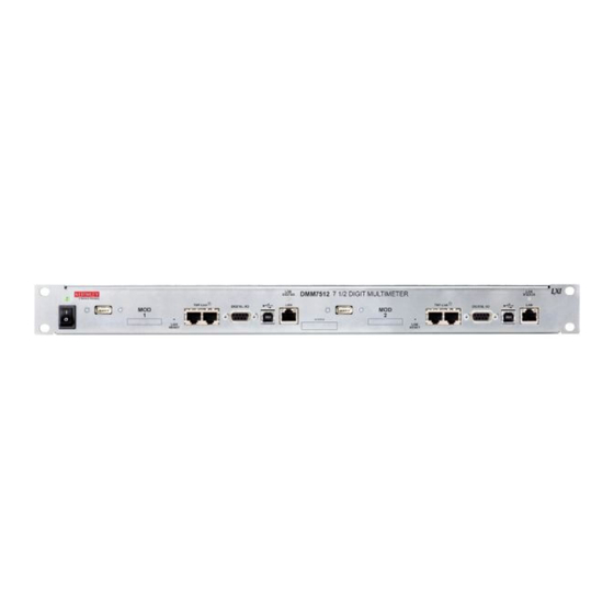
Model DMM7512 7½ Digit Sampling Multimeter
Figure 1: DMM7512 7½ Digit Multimeter
Description
Test lead kit
LAN crossover cable, 16 in.
Shielded crossover cable with RJ-45 connector, 5 ft.
Power line cord
Green and yellow ground cable, 120 in.
Safety precautions
1U rack rail mount
10-32X3/8 Phillips truss head screw
10-32X5/8 Phillips truss head screw
Cage nut
*P071357601*
Instrument Information
Quantity
4
2
1
1
1
1
1
2
4
8
4
1
Advertisement
Table of Contents

Related Manuals for Tektronix KEITHLEY DMM7512


Summary of Contents for Tektronix KEITHLEY DMM7512
- Page 1 Model DMM7512 7½ Digit Sampling Multimeter Keithley Instruments Instrument Information 28775 Aurora Road Cleveland, Ohio 44139 1-800-935-5595 tek.com/keithley Introduction This document describes the DMM7512 7½ Digit Multimeter instrument and how it differs from the Model DMM7510 7½ Digit Multimeter instrument. The DMM7512 is a no-front-panel version of the DMM7510 that has two DMM modules housed in one enclosure.
-
Page 2: Customer Documentation
Model DMM7512 7½ Digit Sampling Multimeter Instrument Information Customer documentation The DMM7512 is very similar to the DMM7510. This document describes the differences between the DMM7512 and the DMM7510. Other than the changes described in this document, the products are identical, so you can use the DMM7510 documents as a resource. -
Page 3: Installing The Dmm7512
Model DMM7512 7½ Digit Sampling Multimeter Instrument Information Differences between the DMM7510 and the DMM7512 The DMM7512 contains two digital multimeters that offer DMM7510 features in a configuration tailored to rack-mount operation. Most DMM7510 functionality is available, with the following exceptions: ▪... - Page 4 Model DMM7512 7½ Digit Sampling Multimeter Instrument Information Dimensions The following figures show the mounting screw locations and other dimensions of the instrument. Figure 2: DMM7512 top view Figure 3: Dimensions - front view 071357601 / October 2018...
-
Page 5: Front Panel Overview
Model DMM7512 7½ Digit Sampling Multimeter Instrument Information Figure 4: Dimensions - side view Front-panel overview The front panel of the DMM7512 is shown below. Descriptions of the controls on the front panel follow the figure. Figure 5: DMM7512 front panel Power indicator The power switch turns the instrument on or off. -
Page 6: Rear Panel Overview
Model DMM7512 7½ Digit Sampling Multimeter Instrument Information Digital I/O port A digital input/output port that detects and outputs digital signals. The port provides six digital I/O lines. Each output is set high (+5 V) or low (0 V) and can read high or low logic levels. Each digital I/O line is an open-drain signal. -
Page 7: Setting Up Remote Communications
Model DMM7512 7½ Digit Sampling Multimeter Instrument Information Measurement Fast-acting current-input fuse. input fuse For continued protection against fire hazard, replace this fuse with a fuse of the same type and rating (Keithley part number DMM7510-FUSE-3A). EXT TRIG This terminal is a TTL-compatible input/output line with a 0 to 5 V IN/OUT terminal logic signal. -
Page 8: Set The Ip Address To Be Set Automatically
Model DMM7512 7½ Digit Sampling Multimeter Instrument Information Set the IP address to be set automatically When the TCP/IP configuration mode is set to Automatic, a DHCP server automatically sets the IP address, subnet mask, and the default gateway. To use this option, a DHCP server must be available on the network. The following steps reset the TCP/IP configuration, which also resets the instrument password. -
Page 9: Accessing The Virtual Front Panel
Model DMM7512 7½ Digit Sampling Multimeter Instrument Information Accessing the virtual front panel If you have a LAN connection, you can access the web interface of each module in the instrument. Each module has its own IP address and is controlled separately. The web interface for each module includes a virtual front panel, which you can use to control the module. -
Page 10: Line Fuse Replacement
Model DMM7512 7½ Digit Sampling Multimeter Instrument Information Line fuse replacement A fuse on the DMM7512 rear panel protects the power line input of the instrument. Disconnect the line cord at the rear panel and remove all test leads connected to the instrument before replacing a line fuse. -
Page 11: Verification And Adjustment
Model DMM7512 7½ Digit Sampling Multimeter Instrument Information Verification and adjustment The DMM7512 contains two independent DMM modules that each support a sub-set of DMM7510 functions and specifications. For supported functions, the commands are identical to DMM7510. To verify and adjust the DMM7512, use the procedures in the Model DMM7510 7½ Digit Graphical Sampling Multimeter Calibration and Adjustment Manual (Keithley document number DMM7510-905-01), with the following exceptions: ▪... -
Page 12: Safety Precautions
Safety precautions The following safety precautions should be observed before using this product and any associated instrumentation. Although some instruments and accessories would normally be used with nonhazardous voltages, there are situations where hazardous conditions may be present. This product is intended for use by personnel who recognize shock hazards and are familiar with the safety precautions required to avoid possible injury. - Page 13 For safety, instruments and accessories must be used in accordance with the operating instructions. If the instruments or accessories are used in a manner not specified in the operating instructions, the protection provided by the equipment may be impaired. Do not exceed the maximum signal levels of the instruments and accessories. Maximum signal levels are defined in the specifications and operating information and shown on the instrument panels, test fixture panels, and switching cards.
Need help?
Do you have a question about the KEITHLEY DMM7512 and is the answer not in the manual?
Questions and answers