Table of Contents
Advertisement
Quick Links
Advertisement
Table of Contents

Related Manuals for Tektronix DMM4020


Summary of Contents for Tektronix DMM4020
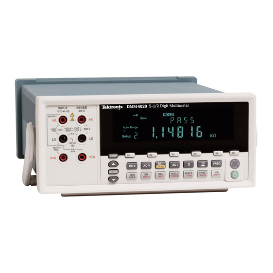
- Page 1 DMM4020 Digital Multimeter Technical Reference Revision B 077-0365-02...
- Page 2 Tektronix products are covered by U.S. and foreign patents, issued and pending. Information in this publication supersedes that in all previously published material. Specifications and price change privileges reserved.
-
Page 3: Table Of Contents
Table of Contents Chapter Title Page Introduction and Specifications ............1-1 General Safety Summary ................... 1-3 To Avoid Fire or Personal Injury .............. 1-3 Symbols and Terms ................... 1-6 Safety and Electrical Symbols ..............1-6 Description of IEC 61010 Measurement Categories ......... 1-7 Introduction ...................... - Page 4 DMM4020 Technical Reference Cleaning ......................2-4 Storing and Shipping the Meter ................. 2-4 Power Considerations ..................2-4 Selecting the Line Voltage ................2-4 Replacing the Fuses ..................2-5 Line-Power Fuse ..................2-5 Current-Input Fuses ................... 2-6 If the Meter Does Not Turn On ................2-7 Display Tests ......................
- Page 5 List of Tables Table Title Page 2-1. Line Voltage to Fuse Rating................... 2-5 3-1. Required Test Equipment ..................3-3 3-2. Direct Voltage Verification Steps ................3-4 3-3. Alternating Voltage Verification Steps ..............3-5 3-4. 4-Wire Ohms Verification Steps ................3-6 3-5.
- Page 6 DMM4020 Technical Reference...
- Page 7 List of Figures Figure Title Page 1-1. IEC 61010 Measurement Category (CAT) Levels ..........1-7 2-1. Replacing the Line Power Fuse ................2-5 2-2. Replacing the Current-Input Fuses ................. 2-7 2-3. Display Elements ....................2-8 3-1. Direct and Alternating Voltage Verification Test Setup ........3-4 3-2.
- Page 8 DMM4020 Technical Reference...
-
Page 9: Title
Chapter 1 Introduction and Specifications Title Page General Safety Summary ..................1-3 To Avoid Fire or Personal Injury ..............1-3 Symbols and Terms ..................1-6 Safety and Electrical Symbols ..............1-6 Description of IEC 61010 Measurement Categories ........1-7 Introduction ......................1-8 Manual Set ...................... - Page 10 DMM4020 Technical Reference...
-
Page 11: General Safety Summary
Introduction and Specifications General Safety Summary General Safety Summary Review the following safety precautions to avoid injury and prevent damage to this product or any other products connected to it. To avoid potential hazards, use this product only as specified. Only qualified personnel should perform service procedures. - Page 12 DMM4020 Technical Reference Do not touch exposed connections and components Avoid Exposed Circuitry. when power is present. Use only the fuse type and rating specified for this product. Use Proper Fuse. Keep Product Surfaces Clean and Dry. Warning To avoid possible electric shock, personal injury, or death, read the following before using the Meter.
- Page 13 Introduction and Specifications General Safety Summary • When making electrical connections, connect the common test lead before connecting the live test lead; when disconnecting, disconnect the live test lead before disconnecting the common test lead. • Disconnect circuit power and discharge all high-voltage capacitors before testing resistance, continuity, diodes, or capacitance.
-
Page 14: Symbols And Terms
DMM4020 Technical Reference Symbols and Terms The following terms and safety and electrical symbols may appear in the manual or on the product: A Warning statement identifies conditions or practices that could result in injury or death. A Caution statement identifies conditions or practices that could result in damage to the Meter or equipment to which it is connected. -
Page 15: Description Of Iec 61010 Measurement Categories
Introduction and Specifications General Safety Summary Description of IEC 61010 Measurement Categories The IEC 61010 safety standard defines four Overvoltage (Installation) Categories (CAT I to CAT IV) based on the magnitude of danger from transient impulses as shown in Figure 1-1. -
Page 16: Introduction
DMM4020 Technical Reference Introduction The DMM4020 Digital Multimeter (hereafter referred to as the Meter) is a 5-1/2 digit dual-display multimeter designed for bench-top, field service, and system applications. The multiple measurement functions, plus the RS-232 remote interface, make the Meter an ideal candidate for precision manual measurements and use in automated systems. -
Page 17: Manual Set
Chapter 1 – Introduction and Specifications This chapter introduces the Tektronix DMM4020 Digital Multimeter, describing its features, and accessories. This chapter also discusses use of the Technical Reference Manual and the various conventions used in describing the meter’s circuitry and presents a complete set of specifications. -
Page 18: General Specifications
DMM4020 Technical Reference General Specifications Voltage 100V Setting ............90 V to 110 V 120V Setting ............. 108 V to 132 V 220V Setting ............. 198 V to 242 V 240V Setting ............. 216 V to 264 V Frequency ............47 Hz to 440 Hz Power Consumption ......... -
Page 19: Electrical Specifications
Introduction and Specifications Electrical Specifications Electrical Specifications Specifications are valid for 5-½ digit mode and after at least a half-hour warm-up. DC Voltage Specifications Maximum Input ..........1000 V on any range Common Mode Rejection ......... 120 dB at 50 or 60 Hz ±0.1% (1 kΩ unbalance) Normal Mode Rejection ........ -
Page 20: Ac Voltage Specifications
DMM4020 Technical Reference AC Voltage Specifications AC Voltage specifications are for ac sinewave signals >5 % of range. For inputs from 1 % to 5 % of range and <50 kHz, add an additional error of 0.1 % of range, and for 50 kHz to 100 kHz, add 0.13 % of range. -
Page 21: Resistance
Introduction and Specifications Electrical Specifications Resistance Specifications are for 4-wire resistance function, or 2-wire resistance with REL. If REL is not used, add 0.2 Ω for 2-wire resistance plus lead resistance. Measurement Method ........Current source referenced to LO input Max Lead Resistance (4-wire ohms) .... -
Page 22: Ac Current
DMM4020 Technical Reference Accuracy Uncertainty Temperature Coefficient/°C Range 90 days 1 year Outside 18 – 28 °C 23 °C ± 5 °C 23 °C ± 5 °C 200 µA 0.02 + 0.005 0.03 + 0.005 0.003 + 0.001 2 mA 0.015 + 0.005... -
Page 23: Frequency
Introduction and Specifications Electrical Specifications Frequency Gate Time ............131 ms Measurement Method ........AC-coupled input using the ac voltage measurement function. Settling Considerations ........When measuring frequency after a dc offset voltage change, errors may occur. For the most accurate measurement, wait up to 1 second to allow input blocking RC time constant to settle. - Page 24 DMM4020 Technical Reference 1-16...
-
Page 25: General Maintenance
Chapter 2 General Maintenance Title Page Introduction ......................2-3 General Maintenance Information ............... 2-3 Required Equipment ..................2-3 Static Safe Handling ..................2-3 Cleaning ....................... 2-4 Storing and Shipping the Meter ................2-4 Power Considerations ..................2-4 Selecting the Line Voltage ................2-4 Replacing the Fuses .................. - Page 26 DMM4020 Technical Reference...
-
Page 27: Introduction
General Maintenance Introduction Introduction This chapter provides handling, cleaning, fuse replacement, and display test instructions for the Meter. General Maintenance Information The following sections describe how to maintain the Meter. Required Equipment Equipment required for calibration, troubleshooting, and repair of the Meter is listed in Table 3-1. -
Page 28: Cleaning
DMM4020 Technical Reference Cleaning Warning To avoid electric shock or damage to the Meter, never get water inside the Meter. Caution To avoid damaging the Meter’s housing, do not apply solvents to the Meter. If the Meter requires cleaning, wipe it down with a cloth lightly dampened with water or a mild detergent. -
Page 29: Replacing The Fuses
General Maintenance Power Considerations Replacing the Fuses The Meter uses one fuse to protect the line-power input and two fuses to protect the current-measurement inputs. Line-Power Fuse The Meter has a line-power fuse in series with the power supply. Table 2-1 indicates the proper fuse for each of the four line-voltage selections. -
Page 30: Current-Input Fuses
DMM4020 Technical Reference Current-Input Fuses The 200 mA and 10 A inputs are protected by user-replaceable fuses. • The 200 mA input is protected by a fuse (F2) rated at 440 mA, 1000 V (fast blow), 10,000 A minimum breaking capacity. -
Page 31: If The Meter Does Not Turn On
See the “Fuse Replacement” section earlier in this chapter for instructions on changing the voltage setting. 5. Verify that the power-line fuse is good. If these steps don’t solve the problem, then contact Tektronix for more help. See the “Contacting Tektronix” section at the beginning of this manual for contact information. -
Page 32: Display Tests
DMM4020 Technical Reference Display Tests The display test consists of turning on all the display elements and checking what appears in the display with Figure 2-3. To turn on all the display elements: 1. Turn the Meter on by moving the rear-panel power switch to the “On” position. -
Page 33: Performance Verification And Calibration
Chapter 3 Performance Verification and Calibration Title Page Introduction ......................3-3 Required Equipment .................... 3-3 Direct Voltage Verification.................. 3-4 Alternating Voltage Verification ................. 3-5 4-Wire Ohms Verification ................... 3-6 2-Wire Ohms Verification ................... 3-7 Direct Current Verification .................. 3-8 Alternate Current Verification ................3-11 Frequency Verification .................. - Page 34 DMM4020 Technical Reference...
-
Page 35: Introduction
Table 3-1. Required Test Equipment Function Instrument Type Model Comments Volts DC Calibrator Fluke 5700A Figure 3-1 4-wire short Tektronix low thermal 4- Tektronix PN 013-0369-00 wire short or equivalent Volts AC Calibrator Fluke 5700A Figure 3-1 Amplifier Fluke 5725A Resistance... -
Page 36: Direct Voltage Verification
DMM4020 Technical Reference Direct Voltage Verification To verify the Volts DC function of the Meter, connect it to the calibrator as shown in Figure 3-1 and apply the voltages listed in Table 3-2. gdb001.eps Figure 3-1. Direct and Alternating Voltage Verification Test Setup Table 3-2. -
Page 37: Alternating Voltage Verification
Performance Verification and Calibration Alternating Voltage Verification Alternating Voltage Verification To verify the Volts AC function of the Meter, connect it to the test equipment as shown in Figure 3-1 and apply the voltage listed in Table 3-3. Table 3-3. Alternating Voltage Verification Steps Nominal Input 90-Day Test Limit 1-Year Test Limit... -
Page 38: 4-Wire Ohms Verification
DMM4020 Technical Reference 4-Wire Ohms Verification To verify the 4-Wire Ohms function of the Meter, connect it to the test equipment as shown in Figure 3-2 and apply the resistances listed in Table 3-4. gdb003.eps Figure 3-2. 4-Wire Ohms Test Setup Table 3-4. -
Page 39: 2-Wire Ohms Verification
Performance Verification and Calibration 2-Wire Ohms Verification 2-Wire Ohms Verification To verify the 2-Wire Ohms function of the Meter, connect it to the test equipment as shown in Figure 3-4 and apply the resistances listed in Table 3-5. gdb002.eps Figure 3-3. 2-Wire Ohms Test Setup Table 3-5. -
Page 40: Direct Current Verification
DMM4020 Technical Reference Table 3-5. 2-Wire Ohms Verification Steps (cont.) 90-Day Test Limit 1-Year Test Limit Nominal Range Input High High 1.9 MΩ 2 MΩ STD+0.00063 MΩ STD-0.00063 MΩ STD+0.00084 MΩ STD-0.00084 MΩ 0 MΩ 20 MΩ 0.0006 MΩ -0.0006 MΩ... - Page 41 Performance Verification and Calibration Direct Current Verification gdb005.eps Figure 3-5. 2 Amps and Greater Direct and Alternating Current Test Setup...
-
Page 42: Direct Current Verification Steps
DMM4020 Technical Reference Table 3-6. Direct Current Verification Steps 90-Day Test Limit 1-Year Test Limit Nominal Range Input High High 0 µA 200 µA 0.010 µA -0.010 µA 0.010 µA -0.010 µA 190 µA 200 µA 190.048 µA 189.952 µA 190.067 µA... -
Page 43: Alternate Current Verification
Performance Verification and Calibration Alternate Current Verification Alternate Current Verification To verify the Amps AC function of the Meter, connect it to the test equipment as shown in either Figure 3-4 or Figure 3-5 depending on current level and apply the current levels listed in Table 3-7. -
Page 44: Frequency Verification
DMM4020 Technical Reference Frequency Verification Use the function generator to apply the frequencies listed in Table 3-8. Table 3-8. Frequency Verification Steps Nominal Input 90-Day Test Limit 1-Year Test Limit Range Ampl. Freq. High High 0.1 V 20 Hz 2000 Hz 20.04 Hz... -
Page 45: Adjustment Steps
Performance Verification and Calibration Adjustment (Calibration) Table 3-9. Adjustment Steps Step Func./Command Point Input Signal Description Volts DC: zero points using the 4-wire short 0 mV/0V 0 mV Zero point of VDC, all ranges Volts DC: Gains – Adjust using 5700A/5725A -199.9 mV -199.9 mV Gain of VDC, 200 mV range... - Page 46 DMM4020 Technical Reference Table 3-9. Adjustment Steps (cont.) Step Func./Command Point Input Signal Description 1 V@1 kHz Gain of VAC, 20 V range 10 V 10 V@1 kHz 15 V 15 V@1 kHz 19.99 V 19.99 V@1 kHz 10 V...
- Page 47 Performance Verification and Calibration Adjustment (Calibration) Table 3-9. Adjustment Steps (cont.) Step Func./Command Point Input Signal Description 10 Ω 10 Ω, 4 Wire OHMS Gain of OHMS, 20 kΩ range 5k Ω, 4 Wire OHMS 5 kΩ OHMS 10 kΩ 10 kΩ, 4 Wire OHMS 15 kΩ...
- Page 48 DMM4020 Technical Reference Table 3-9. Adjustment Steps (cont.) Step Func./Command Point Input Signal Description 0.5 A 0.5 A@500 Hz Gain of AAC, 10 A range 2 A@500 Hz 5 A@500 Hz 10 A 10 A@500 Hz Current DC: zero points – Adjust with 5700A in standby or disconnected 0 µA/0 mA/0 A...
-
Page 49: Rs-232 Calibration (Manual)
Performance Verification and Calibration Adjustment (Calibration) When the last calibration point for the selected function finishes, the Meter will go to IDLE mode where appears in the secondary display and six flashing dashes appear in the primary display. Return to step 1 above and select the next function for calibration. Press to exit the calibration mode at any time. -
Page 50: Calibration Points
DMM4020 Technical Reference Send the string “EXIT” to exit the calibration mode at any time. If a function has not been completely calibrated, a CAL ERROR will be displayed. Note When the Meter returns a recommended calibration value followed by “W4”, 4-wire compensation is enabled on the input. - Page 51 Performance Verification and Calibration Adjustment (Calibration) {//vdc {0.0, -0.1999, -0.1, 0.1, 0.1999}, range 1 {0.0, -1.999, -1.0, 1.0, 1.999}, range 2 {0.0, -19.990, -10.0, 10.0, 19.990}, range 3 {0.0, -199.90, -100.0, 100.0, 199.9}, range 4 {0.0, -1000.0, -500.0, 500.0, 1000.0}, range 5 {//vac {0.0, 0.05, 0.10, 0.15, 0.1999},...
- Page 52 DMM4020 Technical Reference 3-20...
Need help?
Do you have a question about the DMM4020 and is the answer not in the manual?
Questions and answers