Table of Contents
Advertisement
Quick Links
Advertisement
Table of Contents

Subscribe to Our Youtube Channel
Related Manuals for Tektronix Keithley DMM7510


Summary of Contents for Tektronix Keithley DMM7510
- Page 1 Model DMM7510 Quick Start Guide...
-
Page 2: Safety Precautions
Safety precautions overvoltages often associated with local AC mains connections. Certain Keithley measuring instruments may be connected to mains. These instruments will be marked as category II The following safety precautions should be observed before using this product and any or higher. - Page 3 Do not touch any object that could provide a current path to the common side of the circuit under The WARNING heading in the user documentation explains hazards that might result test or power line (earth) ground. Always make measurements with dry hands while standing on in personal injury or death.
-
Page 4: Power And Environmental Specifications
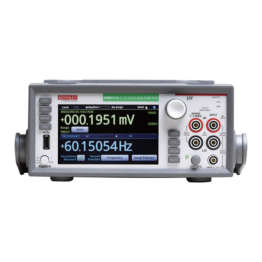
Power and environmental specifications For indoor use only. 100 V to 240 V 50 Hz to 60 Hz Power supply (automatically sensed at power up) 60 VA Maximum VA Maximum 2000 m (6562 ft) above sea level Operating altitude 0 °C to 50 °C, less than 80% relative humidity Operating temperature at 35 °C -30 °C to +70 °C... - Page 5 Introduction The 7510 documentation includes: The Model DMM7510 is a 7 ½ digit graphical sampling multimeter that expands standard digital multimeter (DMM) Quick Start Guide: This document. It provides • functions with high-speed digitizing and a large color unpacking instructions, describes basic connections, and graphical touchscreen display.
-
Page 6: Unpack And Inspect The Instrument
Unpack and inspect the instrument To unpack and inspect the instrument: 1. Inspect the box for damage. Do not lift the DMM7510 by the front bezel. Lifting the 2. Open the top of the box. instrument by the front bezel can cause instrument 3. - Page 7 You should have received the DMM7510 with the following accessories: 1. USB-B-1 USB cable, Type A to Type B, 1 m (3.28 ft) 2. Crossover cable for TSP-Link or ethernet connections 3. Power-line cord 4. Model 1756 Standard Test Lead Kit 5.
- Page 8 Connect the instrument Important test system safety information • Read and comply with the specifications of all This product is sold as a stand-alone instrument that may become part of a system that could contain hazardous instruments in the system. The overall allowed signal voltages and energy sources.
- Page 9 • Make sure all connections are behind a locked cabinet door or other barrier. This protects the system operator from accidentally removing a connection by hand and To keep users safe, always read and follow all safety exposing hazardous voltages. Use high-reliability, fail- warnings provided with each of the instruments in your system.
-
Page 10: Install The Instrument
Install the instrument You can use the DMM7510 on a bench or in a rack. If you are installing the DMM7510 in a rack, please see the The power cord supplied with the DMM7510 contains a instructions that came with your rack-mount kit. separate protective earth (safety ground) wire for use To prevent damaging heat build-up and ensure specified with grounded outlets. - Page 11 The DMM7510 must be turned on and allowed to warm up for at least 90 minutes to achieve rated accuracies. To connect line power and turn on the instrument: 1. Make sure the front-panel power switch is in the off (0) position.
- Page 12 Explore the DMM7510 Measure functions DC voltage AC voltage Home Temperature Continuity Go to home screen DCV ratio DC current AC current Menu Frequency Capacitance Go to menu screen 2W resistance 4W resistance Period Diode Digitize functions Digitize voltage Digitize current Touch!
- Page 13 View Change measurement communications method settings Continuous Manual View events Select where Trigger model Errors readings are Warnings stored Information Empty program Full Touch! Explore...
- Page 15 Measure settings Active measure function Press to change Settings for Swipe screen active function for more content Explore...
- Page 16 A buffer stores readings. Where do +0.1621057 V measurements defbuffer1 Default In the active buffer you select defbuffer2 buffers View the buffer data > MENU myBuff1 Use a default buffer User-created or create your own buffers test2 Reading Buffer > >...
- Page 17 View data Save to USB What can you do Stored as a .csv le Touch to with buffer display details Plot data on a graph data? Explore...
- Page 18 Touch to initiate Graphing trigger model SmartScale ® Touch to scale IDLE automatically You can pinch to zoom in Touch any point to see more information Swipe to see Scale, Buffer Stats, and Cursor...
- Page 19 Trigger Scale Scaling options Similar to oscilloscope triggering Show All Readings Analog Edge Show Group of Readings Show New Readings Analog Pulse SmartScale Picks scale for you Data based on available data Select which data to graph Analog Window External Digital Inputs Explore...
-
Page 20: Getting Help
Getting help Turn navigation control to change selection Highlight the object you want help with Press the HELP key... -
Page 21: Connections For Testing
Connections for testing Do not apply more than 1000 V to the INPUT To prevent electric shock, test connections must be PEAK terminals or more than 350 V to the SENSE terminals. configured such that the user cannot come in contact PEAK Failure to heed this caution may result in instrument with test leads or any device under test (DUT) that is... - Page 22 The physical connections for the front panel are shown in the following figures. Note that you must use either the front terminals or rear terminals — you cannot mix connections. The front-panel and rear-panel connections are safety banana jacks. The example in this guide shows you how to make connections to the front panel and short the connections.
- Page 23 Verify measurement operation To view the measurements on the graph screen: The following steps provide a quick way to verify that the instrument is operating correctly. 1. Press the MENU key. 2. Under Views, select Graph. To verify measurement operation: 1.
- Page 24 FAQs My data looks odd or is wrong. What should I do? Verify the connections from the instrument to the test fixture. Also check the connections from the DUT to the test fixture How do I save data to a USB flash drive? socket.
-
Page 25: Next Steps
Next steps Why did my settings change? Many of the settings in the DMM7510 are saved with the function that was active when you set them. For example, For more information, see the Keithley Instruments website, assume you have measure function set to current and set a tek.com/keithley for the following documents: value for the number of digits to display. - Page 26 Contact information: Middle East, Asia, and North Africa Find more valuable resources at TEK.COM Australia* 1 800 709 465 Copyright © 2019, Tektronix. All rights reserved. +41 52 675 3777 Austria 00800 2255 4835 Tektronix products are covered by U.S. and The Netherlands* 00800 2255 4835 foreign patents, issued and pending.
Need help?
Do you have a question about the Keithley DMM7510 and is the answer not in the manual?
Questions and answers