Tektronix DMM4040 User Manual
Hide thumbs
Also See for DMM4040:
- Safety and installation instructions manual (38 pages) ,
- Installation manual (7 pages)
Table of Contents
Advertisement
Quick Links
Download this manual
See also:
Installation Manual
Advertisement
Table of Contents

Related Manuals for Tektronix DMM4040


Summary of Contents for Tektronix DMM4040
- Page 1 DMM4040 and DMM4050 Digital Multimeter Users Manual 077-0361-00...
- Page 2 Tektronix products are covered by U.S. and foreign patents, issued and pending. Information in this publication supersedes that in all previously published material. Specifications and price change privileges reserved.
- Page 3 Tektronix, shipping charges prepaid, and with a copy of customer proof of purchase. Tektronix shall pay for the return of the product to Customer if the shipment is to a location within the country in which the Tektronix service center is located. Customer shall be responsible for paying all shipping charges, duties, taxes, and any other charges for products returned to any other locations.
-
Page 5: Table Of Contents
Table of Contents Chapter Title Page Introduction and Specifications............1-1 General Safety Summary ................... 1-3 Compliance Information ..................1-8 EMC Compliance ..................1-8 Safety Compliance..................1-9 Environmental Considerations................1-10 Product End-of-Life Handling............... 1-10 Introduction......................1-11 User Documentation ..................1-12 About this Manual ..................... 1-12 Instrument Security Procedures ................. - Page 6 DMM4040 and DMM4050 Users Manual Additional Errors ................... 1-25 Continuity ...................... 1-25 Diode Test ..................... 1-26 Measurement Rates (IEEE488[4])..............1-26 Preparing the Meter for Operation ............. 2-1 Introduction......................2-3 Unpacking and Inspecting the Meter ..............2-3 Storing and Shipping the Meter ................. 2-3 Power Considerations ..................
- Page 7 (continued) Contents Managing Memory ..................3-23 Controlling System-Related Operations ............3-24 Identifying Meter Errors................3-24 Querying the Firmware for Revision Level........... 3-24 Adjusting Display Brightness................ 3-25 Setting the Meter’s Date and Time..............3-25 USB Operation ....................3-25 USB Storage Capacity and Write Time............3-25 USB Memory Device Compatibility and Special Instruction .......
- Page 8 DMM4040 and DMM4050 Users Manual...
- Page 9 Non-volatile Memory Space .................. 1-13 1-3. Accessories......................1-14 2-1. Line Voltage to Fuse Rating................... 2-5 2-2. Line-Power Cord Types Available from Tektronix ..........2-7 3-1. Front-Panel Controls and Connectors ..............3-4 3-2. Display Elements ....................3-6 3-3. Rear-Panel Connectors................... 3-7...
- Page 10 DMM4040 and DMM4050 Users Manual...
- Page 11 List of Figures Figure Title Page 1-1. IEC 61010 Measurement Category (CAT) Levels..........1-7 2-1. Replacing the Line Fuse..................2-5 2-2. Replacing the Current Input Fuses ................. 2-6 2-3. Bail Adjustment and Removal ................2-8 3-1. TrendPlot Display ....................3-15 3-2.
- Page 12 DMM4040 and DMM4050 Users Manual viii...
-
Page 13: Introduction And Specifications
Chapter 1 Introduction and Specifications Title Page General Safety Summary ..................1-3 Compliance Information ..................1-8 EMC Compliance .................... 1-8 Safety Compliance................... 1-9 Environmental Considerations................1-10 Product End-of-Life Handling................. 1-10 Introduction......................1-11 User Documentation .................... 1-12 About this Manual ....................1-12 Instrument Security Procedures ................ - Page 14 DMM4040/4050 Users Manual Continuity ......................1-25 Diode Test ....................... 1-26 Measurement Rates (IEEE488[4])..............1-26...
-
Page 15: General Safety Summary
Introduction and Specifications General Safety Summary General Safety Summary Review the following safety precautions to avoid injury and prevent damage to this product or any other products connected to it. To avoid potential hazards, use this product only as specified. Only qualified personnel should perform service procedures. - Page 16 DMM4040/4050 Users Manual Do Not Operate With Suspected Failures. If you suspect that there is damage to this product, have it inspected by qualified service personnel. Avoid Exposed Circuitry. Do not touch exposed connections and components when power is present.
- Page 17 Introduction and Specifications General Safety Summary Use caution when working with voltages above 30 V ac rms, 42 V ac peak, or 42 V dc. These voltages pose a shock hazard. Use only the replacement fuse(s) specified by the manual. Use the proper terminals, function, and range for your measurements.
- Page 18 DMM4040/4050 Users Manual Symbols and Terms The following terms and safety and electrical symbols may appear in the manual or on the product: A XW Warning statement identifies conditions or practices that could result in injury or death. A W Caution statement identifies conditions or practices that could result in damage to the Meter or equipment to which it is connected.
- Page 19 Introduction and Specifications General Safety Summary Description of IEC 61010 Measurement Categories The IEC 61010 safety standard defines four Overvoltage (Installation) Categories (CAT I to CAT IV) based on the magnitude of danger from transient impulses as shown in Figure 1-1.
-
Page 20: Compliance Information
EN 61000-3-2:2006. AC power line harmonic emissions. EN 61000-3-3:1995. Voltage changes, fluctuations, and flicker. European Contact. Tektronix UK, Ltd. Western Peninsula Western Road Bracknell, RG12 1RF United Kingdom This product is intended for use in nonresidential areas only. Use in residential areas may cause electromagnetic interference. -
Page 21: Safety Compliance
Introduction and Specifications Compliance Information Australia / New Zealand Declaration of Conformity – EMC Complies with the EMC provision of the Radiocommunications Act per the following standard, in accordance with ACMA: CISPR 11:2003. Radiated and Conducted Emissions, Group 1, Class A, in accordance with EN 61326-1:2006 and EN 61326-2-1:2006. -
Page 22: Environmental Considerations
Directives 2002/96/EC and 2006/66/EC on waste electrical and electronic equipment (WEEE) and batteries. For information about recycling options, check the Support/Service section of the Tektronix Web site (www.tektronix.com). Restriction of Hazardous Substances This product has been classified as Monitoring and Control equipment, and is outside the scope of the 2002/95/EC RoHS Directive. -
Page 23: Introduction
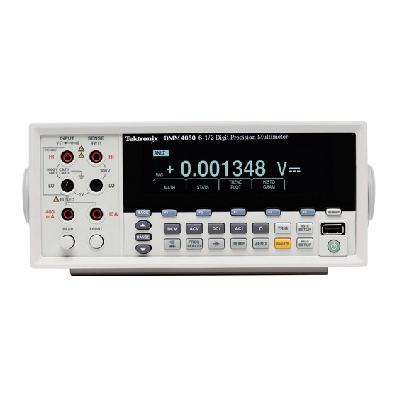
Introduction and Specifications Introduction Introduction The DMM4040 and DMM4050 are 6-1/2 digit, dual-display multimeters designed for bench-top, field service, and system applications. Their full complement of measurement functions plus its RS-232, IEEE 488, and Ethernet Remote Interfaces makes these multimeters ideal candidates for precision manual measurements and use in automated systems. -
Page 24: User Documentation
Russian About this Manual This is the Users Manual for the DMM4040 and DMM4050 Digital Multimeters (hereafter referred to as the Meter). It contains all of the information a new user will need to operate the Meter effectively. The manual is divided into the following chapters: Chapter 1 “Introduction and Specifications”... -
Page 25: Instrument Security Procedures
Introduction and Specifications Instrument Security Procedures Instrument Security Procedures This section describes the Meter’s memory elements and the procedures for clearing them. Volatile Memory Table 1-1 lists the Meter’s volatile memory elements. Table 1-1. Volatile Memory Space Type Size Function SDRAM 128 MB Out-guard measurement data, user strings, temporary configuration information,... -
Page 26: Media Memory
DMM4040/4050 Users Manual Media Memory The Meter has a front-panel USB port for connecting flash memory modules up to 2 Gigabytes capacity to store Meter configuration and measurement data. To clear a memory module: 1. Press M. 2. Press the MANAGE MEMORY soft key. -
Page 27: General Specifications
Introduction and Specifications General Specifications General Specifications Power Voltage 100 V Setting ............90 V to 110 V 120 V Setting ............108 V to 132 V 220 V Setting ............198 V to 242 V 240 V Setting ............216 V to 264 V Frequency ............... -
Page 28: Remote Interfaces
DMM4040/4050 Users Manual Overrange ............... 20 % on all ranges except 1000 V dc, 1000 V ac Diode, and 10 A ranges Remote Interfaces RS-232C, DTE 9-pin, 1200 to 230400 baud (RS-232C to USB cable available to connect the Meter to a PC USB port. -
Page 29: Ac Voltage Specifications
Introduction and Specifications Electrical Specifications 4050 Accuracy Accuracy is given as (% measurement + % of range) Temperature 24 Hour 90 Days 1 Year Range Coefficient/ C (23 1 C) (23 5 C) (23 5 C) Outside 18 to 28 C 100 mV 0.0025 + 0.003 0.0025 + 0.0035... -
Page 30: Input Characteristics
DMM4040/4050 Users Manual Input Characteristics Resolution Range Resolution Input Impedance 4½ Digits 5½ Digits 6½ Digits 100 mV 100.0000 mV 100 nV 10 V 1.000000 V 100 V 10 V 2 % shunted 10 V 10.00000 V 1 mV 100 V 10 V by <100 pf... -
Page 31: Resistance
Introduction and Specifications Electrical Specifications Additional Low Frequency Errors Error is stated as % of reading. AC Filter Frequency 3 HZ (slow) 20 HZ (medium) 200 HZ (fast) 10 – 20 Hz 0.25 – 20 – 40 Hz 0.02 – 40 –... -
Page 32: Dc Current
DMM4040/4050 Users Manual 4040/4050 Accuracy Accuracy is given as (% measurement + % of range) Temperature 24 Hour 90 Days 1 Year Range Coefficient/ C (23 1 C) (23 5 C) (23 5 C) Outside 18 to 28 C 0.003 + 0.01 0.008 + 0.03... -
Page 33: Additional Current Errors
Introduction and Specifications Electrical Specifications Accuracy (4040/4050) Accuracy is given as (% measurement + % of range) Temperature 24 Hour 90 Days 1 Year Range Coefficient/ C (23 1 C) (23 5 C) (23 5 C) Outside 18 to 28 C 100 A 0.01 + 0.02 0.04 + 0.025... -
Page 34: Ac Current
DMM4040/4050 Users Manual AC Current The following ac current specifications are for sinusoidal signals with amplitudes greater than 5 % of range. For inputs from 1 % to 5 % of range, add an additional error of 0.1 % of range. - Page 35 Introduction and Specifications Electrical Specifications 4040/4050 Accuracy Accuracy is given as (% measurement + % of range) Temperature 24 Hour 90 Days 1 Year Frequency Range Coefficient/ C (Hz) (23 1 C) (23 5 C) (23 5 C) Outside 18 to 28 C 3 –...
-
Page 36: Frequency
DMM4040/4050 Users Manual Additional Low Frequency Errors Error is stated as % of reading. AC Filter Frequency 3HZ (slow) 20HZ (medium) 200HZ (fast) 10 – 20 Hz 0.25 – 20 – 40 Hz 0.02 – 40 – 100 Hz 0.01 0.55... -
Page 37: Capacitance (4050 Only)
Introduction and Specifications Electrical Specifications Capacitance (4050 Only) Accuracy is stated as (% of measurement + % of range) 1 Year Accuracy Temperature Coefficient/ C Range Resolution (23 5 C) Outside 18 to 28 C 1 nF 1 pF 0.05 + 0.05 2.5 % 10 nF 10 pF... -
Page 38: Diode Test
DMM4040/4050 Users Manual Diode Test Test Current ............100 A or 1 mA Response Time............300 samples/sec with audible tone. Accuracy is given as (% measurements + % of range) Temperature 24 Hour 90 Days 1 Year Range Coefficient/ C... -
Page 39: Preparing The Meter For Operation
Chapter 2 Preparing the Meter for Operation Title Page Introduction......................2-3 Unpacking and Inspecting the Meter ..............2-3 Storing and Shipping the Meter ................2-3 Power Considerations ..................2-3 Selecting the Line Voltage ................2-3 Replacing the Fuses..................2-4 Line-Power Fuse ..................2-4 Current-Input Fuses.................. - Page 40 DMM4040/4050 Users Manual...
-
Page 41: Introduction
Carefully unpack the Meter from its shipping container and inspect the contents for damaged or missing items. If the Meter appears damaged or something is missing, contact both the carrier and Tektronix immediately. Save the container and the packing material in case you have to return the Meter. -
Page 42: Replacing The Fuses
DMM4040/4050 Users Manual 5. Replace the selector block back into the fuse holder. Changing the line voltage setting may require a different line-power fuse for proper operation. Check Table 2-1 for the appropriate fuse for the selected line voltage. With the voltage set and appropriate fuse installed, replace the fuse holder back into the Meter and reconnect the power cord. -
Page 43: Current-Input Fuses
W Warning For protection against fire or arc flash, replace a blown fuse only with one from Tektronix. To test for a blown Current Input Fuse: 1. With the Meter powered up, plug a test lead into the V GER connector. -
Page 44: Connecting To Line Power
DMM4040/4050 Users Manual 1. Turn the Meter off, unplug the power cord from the Meter, and remove all test leads. 2. Turn the Meter on its back. 3. Unscrew the retaining screw on the fuse access door as depicted in Figure 2-2. -
Page 45: Turning Power-On
2. Verify that the correct fuse for the line voltage is installed. 3. Connect the power cord to a properly grounded three-prong outlet. Refer to Table 2-2 for descriptions of the line-power cord types available from Tektronix. Table 2-2. Line-Power Cord Types Available from Tektronix... -
Page 46: Installing The Meter In An Equipment Rack
The Fluke 45 emulation mode enables you to use programs that run on the Fluke 45 multimeter model on the Tektronix DMM4040 and DMM4050. See Sample Program Using the RS-232 Computer Interface in Chapter 3 to view a sample program. - Page 47 Preparing the Meter for Operation Fluke 45 Emulation Mode To switch the Meter to Fluke 45 emulation: 1. Press I. 2. Press 2 to select the COMMANDS menu. This will now show the current command setup. 3. Press 2 to select Fluke 45. The active mode will appear bright in the display, while the other is dim.
- Page 48 DMM4040/4050 Users Manual 2-10...
-
Page 49: Front-Panel Operation
Chapter 3 Front-Panel Operation Title Page Introduction......................3-3 Controls and Indicators ..................3-4 Front-Panel Feature Descriptions ..............3-4 Display Panel....................3-5 Rear-Panel Connectors ..................3-7 Adjusting the Meter’s Range................3-8 Navigating the Front-Panel Menu................ 3-8 Configuring the Meter for a Measurement ............3-8 Setting the Beeper State................... - Page 50 DMM4040/4050 Users Manual Identifying Meter Errors.................. 3-24 Querying the Firmware for Revision Level............. 3-24 Adjusting Display Brightness................3-25 Setting the Meter’s Date and Time..............3-25 USB Operation ....................3-25 USB Storage Capacity and Write Time............3-25 USB Memory Device Compatibility and Special Instruction ......3-26 Configuring the Remote Interface ...............
-
Page 51: Introduction
Front-Panel Operation Introduction Introduction The Meter can be controlled either by sending commands through one of its communication interfaces or by manually operating its front panel controls. This chapter explains the function and use of the controls and indicators located on the front and rear panels of the Meter. -
Page 52: Controls And Indicators
DMM4040/4050 Users Manual Controls and Indicators Front-Panel Feature Descriptions Table 3-1 shows the Meter’s front-panel controls and connectors. Table 3-1. Front-Panel Controls and Connectors TEKTRONIX 6-1/2 DIGIT PRECISION MULTIMETER INPUT SENSE DMM4050 2W/4W 1000 V CAT I 300V 600V CAT II... -
Page 53: Display Panel
Front-Panel Operation Controls and Indicators Table 3-1. Front-Panel Controls and Connectors (cont.) Item Description Memory key for accessing internal and external memory containing meter setups and measurements. See the “Accessing and Controlling Memory” section for more information. USB Port. Connection for USB memory device that can be used to store meter readings (memory device not included). - Page 54 DMM4040/4050 Users Manual Table 3-2. Display Elements 100.0002 -0.4561 123.123. 123.123. ENTER caw02f.eps Item Description Primary display. Secondary display. Indicates PASS, HIGH or LOW for limits testing. Math function selected. Error detected. Memory enabled for storing readings. Extinguishes when last sample is stored.
-
Page 55: Rear-Panel Connectors
RS-232 400 mA TRIG I/O LR44340 WARNING: SERIAL TAG TO AVOID ELECTRIC SHOCK GROUNDING CONNECTOR TEKTRONIX CORPORATION Assembled in USA IN POWER CORD NO INTERNAL USER SERVICEABLE PARTS www.tektronix.com MUST BE CONNECTED REFER SERVICE TO QUALIFIED SERVICE PERSONNEL gdc05.eps Item... -
Page 56: Adjusting The Meter's Range
DMM4040/4050 Users Manual Adjusting the Meter’s Range The range keys, (URV), switch the Meter between auto and manual ranging. The presence or absence of MAN in the display indicates the Meter’s ranging mode. All functions utilize these keys to control the Meter’s range except continuity, diode test, temperature (4050 only), frequency and period, which only have a single range. -
Page 57: Setting The Display Resolution
Front-Panel Operation Configuring the Meter for a Measurement The beeper state is stored in non-volatile memory and does not change when the Meter is turned off or after a remote interface reset. The beeper is enabled when the Meter is shipped from the factory. -
Page 58: Setting Continuity Resistance Threshold And Diode Test Parameters
DMM4040/4050 Users Manual Note The 20 Hz filter is the power-up default selection. Setting Continuity Resistance Threshold and Diode Test Parameters The threshold resistance value for the continuity function and the amount of current and voltage used for Diode testing are adjustable. Continuity resistance threshold can be set to four different values: 1 , 10 , 100 and 1 k . -
Page 59: Using The Analyze Functions
Front-Panel Operation Using the Analyze Functions 2. Press the MORE soft key. 3. Press the HIGH INPUT Z soft key. The soft key label becomes highlighted to indicate high input Z is activated. Press the soft key again to disable the function. Using the Analyze Functions The Meter is capable of performing mathematical operations with measured values, as well as tracking a series of measurements. -
Page 60: Testing Using Limits
DMM4040/4050 Users Manual Stopping Measurement Collection There are two methods of stopping the collection of measurements for the statistics function. To manually stop the measurement collection, press the STOP soft key from the statistics menu. The display will update with the final set of statistical data. -
Page 61: Setting An Offset Value
Front-Panel Operation Using the Analyze Functions With the desired digit selected, press the soft key labeled -- to decrement the digit or ++ to increment the character. The right most character is the multiplier. This character can be set to p, n, , m, k, M, or G. 5. -
Page 62: Using Trendplot
DMM4040/4050 Users Manual To make an mX+B calculation: 1. Press J. 2. Press the MATH soft key. 3. Press the €X+B soft key. To enter the M value: 4. Press the €X soft key To select the digit to adjust, press either <-- or -->. - Page 63 Front-Panel Operation Using the Analyze Functions plot point. Previously laid down plot marks are adjusted down in size proportionally to the new vertical axis. The left section of the Meter’s display indicates the highest (maximum) and lowest (minimum) reading taken since the start of a TrendPlot session. In addition, the length of the TrendPlot session is displayed in hours, minutes, and seconds (hh:mm:ss).
-
Page 64: Using The Histogram Function
DMM4040/4050 Users Manual To stop the TrendPlot session, press B or the STOP soft key. To start the TrendPlot session over, press the STOP soft key followed by the RESTART soft key. Using the Histogram Function The Histogram function provides a graphical representation of the standard deviation of a series of measurements. -
Page 65: Choosing A Trigger Source
Front-Panel Operation Controlling Trigger Functions covered in the Programmers Manual. The following sections discuss triggering the Meter automatically (internal trigger), or externally using the trigger key on the front panel and the trigger connector on the rear-panel. Setup and control of the trigger function is accessible through the Meter’s Measurement Setup key L. -
Page 66: Setting The Trigger Delay
The external memory connects through the USB port on the front panel of the Meter. Optional Memory in various storage capacities is available from Tektronix. See the “Options and Accessories” section in Chapter 1 for Tektronix part numbers. In 3-18... -
Page 67: Storing Readings In Memory
Front-Panel Operation Controlling Trigger Functions addition to storing and recalling readings and configurations, a memory management function is available to delete files. To access the Memory functions, press the M key. The memory menu appears over the five soft keys: RECALL CONFIG, RECALL READING, STORE CONFIG, STORE READINGS, and MANAGE MEMORY. -
Page 68: Recalling Readings From Memory
DMM4040/4050 Users Manual To store readings in external memory 1. Press M. 2. Press the STORE READINGS soft key. 3. Press the USB soft key. 4. Press the #SAMPLES soft key. 5. To adjust the number of samples, press either <-- or --> to select a digit. -
Page 69: Storing Meter Configuration Information
Front-Panel Operation Controlling Trigger Functions Storing Meter Configuration Information Up to five meter configurations can be stored in the Meter’s internal memory. An additional 99 configurations can be stored in the external memory with optional USB memory installed. To store a meter configuration in the Meter’s internal memory: 1. -
Page 70: Storing The Power-Up Configuration
DMM4040/4050 Users Manual Storing the Power-up Configuration To store the Meter’s present configuration as a power-up configuration: 1. Press M. 2. Press the STORE CONFIG softkey. 3. Press the STORE POWER-UP softkey. The Meter configuration stored as a power-up configuration will be set whenever the Meter is powered on. -
Page 71: Recalling A Meter Configuration
Front-Panel Operation Controlling Trigger Functions Recalling a Meter Configuration To recall a configuration from internal memory: 1. Press M. 2. Press the RECALL CONFIG soft key. 3. Press the RECALL INT MEM soft key. 4. Press the soft key labeled with the memory location (CONFIGA through CONFIGE). -
Page 72: Controlling System-Related Operations
DMM4040/4050 Users Manual To clear internal memory contents: 3. Press M. 4. Press the MANAGE MEMORY soft key as shown below. 9.30011 caw062.eps 5. Press the ERASE MEMORY soft key. 6. If you are sure you want to clear all stored readings, all stored configurations, the user string and the hostname from internal memory, press the ERASE soft key. -
Page 73: Adjusting Display Brightness
Front-Panel Operation Controlling System-Related Operations 3. Press the soft key under VERSIONS + SN under the Setup menu. The display shows the outguard software version (OutG SW), the inguard software version (InG SW), the outguard hardware version (OutG HW) and the inguard hardware version (InG HW). -
Page 74: Usb Memory Device Compatibility And Special Instruction
DMM4040/4050 Users Manual The front panel display shows “BUSY WRITING USB" during the write. For 10,000 samples, the write time will typically take ~14 seconds. In ACV, you can press dB, dBm, or zero while data is being stored. Units (and dgC, dgF, K etc) can be changed in the middle of a USB readings file as well. - Page 75 Front-Panel Operation Sample Program Using the RS-232 Computer Interface gdb23f.eps Figure 3-3. Sample Program for RS-232 Computer Interface 3-27...
-
Page 76: Checking The Meter's Calibration Date
DMM4040/4050 Users Manual Checking the Meter’s Calibration Date To read the Meter’s calibration date: 1. Press I 2. Press the CAL soft key as shown below. 0.5993 caw034.eps 3. Press the CAL DATE soft key to display the date the Meter was last calibrated. -
Page 77: Making Measurements
Chapter 4 Making Measurements Title Page Introduction......................4-3 Selecting Function Modifiers................4-3 Activating the Secondary Display ..............4-3 Measuring Voltage.....................4-4 Measuring DC Voltage..................4-4 Measuring AC Voltage..................4-6 Measuring Frequency and Period ..............4-7 Measuring Resistance ..................4-8 Making a Two-wire Resistance Measurement ..........4-8 Making a Four-wire Resistance Measurement ..........4-9 Measuring Current .....................4-10 Measuring DC Current ..................4-12 Measuring AC Current ..................4-13... - Page 78 DMM4040/4050 Users Manual...
-
Page 79: Introduction
Making Measurements Introduction Introduction XW Warning To avoid possible electrical shock, and/or damage to the Meter, Read the safety information found in Chapter 1 before operating this meter. Do not apply more than 1000 volts between any terminal and earth ground. This chapter covers the steps for making a measurement with each of the Meter’s functions. -
Page 80: Measuring Voltage
DMM4040/4050 Users Manual Measuring Voltage The Meter is capable of measuring up to 1000 V dc, 750 V ac (4040) or 1000 V ac (4050). W Caution To avoid blowing the current fuses and possible damage to other equipment, do not apply voltage to the meter’s input until the test leads are properly connected to the input, and the proper voltage function selected. - Page 81 Making Measurements Measuring Voltage Function modifiers: A filter for quieting noisy measurments. This filter averages readings D FLTR to reduce reading noise when in immedicate trigger mode or when in trigger mode with an unending number of triggers selected. The filter is only available for dc functions at rates slower than 1 PLC.
-
Page 82: Measuring Ac Voltage
DMM4040/4050 Users Manual Measuring AC Voltage To make an ac voltage measurement: 1. Press A. The ac voltage icon VB will appear in display as shown below. 0.3861 caw022.eps 2. Connect the test leads to the Meter’s input as shown in Figure 4-1. -
Page 83: Measuring Frequency And Period
Making Measurements Measuring Frequency and Period The available impedance settings are presented in sets of three values. To move to a higher set of impedance values, press ++ -->. Press <-- -- to go to a lower set of impedance values. 3. -
Page 84: Measuring Resistance
DMM4040/4050 Users Manual Function modifiers: APERTURE Displays three different gate time selections: 0.01, 0.1 and 1 second. These selections set the minimum amount of time the Meter takes to measure frequency. Shorter gate times result in lower measurement resolution. 2ND MEAS Cycles the secondary display through the measurement functions listed below, and then off. -
Page 85: Making A Four-Wire Resistance Measurement
Making Measurements Measuring Resistance Note For best results, the filter may require zeroing during the ohms function. Refer to the “Range Keys” section in Chapter 3 of this manual for information on how to adjust the measurement range. Making a Four-wire Resistance Measurement The Meter incorporates two methods of making a four-wire resistance measurement. -
Page 86: Measuring Current
DMM4040/4050 Users Manual To make a four-wire resistance measurement using Tektronix’s 2X4 test leads: 1. Connect the test leads to the Meter’s input connectors as show in Figure 4-3. 2. Press N. 3. If not already highlighted, press the 2X4WIRE soft key. - Page 87 Making Measurements Measuring Current W Caution To avoid blowing the current input fuse or possibly damaging the Meter: Current measurements between 400 mA and 10 A should be measured using only the 10 A and LO input connectors. BEFORE applying power to the circuit to be measured, ensure the test leads are correctly connected to the Meter inputs appropriate for the expected current.
-
Page 88: Measuring Dc Current
DMM4040/4050 Users Manual Refer to the “Range Keys” section in Chapter 3 of this manual for information on how to adjust the measurement range. Measuring DC Current To measure dc current: 1. Connect the test leads between the Meter’s input connectors and the measured circuit as shown in Figure 4-4 for currents 400 mA or less or Figure 4-5 for currents up to 10 amps. -
Page 89: Measuring Ac Current
Making Measurements Measuring Current Function modifiers: A filter for quieting noisy measurments. This filter averages readings D FLTR to reduce reading noise when in immedicate trigger mode or when in trigger mode with an unending number of triggers selected. The filter is only available for dc functions at rates slower than 1 PLC. -
Page 90: Measuring Capacitance (4050 Only)
(Input Lo and 400 ma or 10A) connectors. Measuring Capacitance (4050 only) The Tektronix 4050 is capable of measuring capacitance from 1 pF to 100 mF (0.1 F). To make a capacitance measurement: 1. Press C. An example of the capacitance display is shown below. -
Page 91: Measuring Rtd Temperature (4050 Only)
Refer to the “Range Keys” section in Chapter 3 of this manual for information on how to adjust the measurement range. Measuring RTD Temperature (4050 only) The Tektronix 4050 is capable of measuring temperatures between -200 C and 600 C using Resistance Temperature Detectors (RTDs). To make a temperature measurement: 1. -
Page 92: Testing Continuity
DMM4040/4050 Users Manual 2. Press T to display the measured temperature as shown below. - 246.645 º caw11f.eps To change the temperature scale, refer to the “Setting the Default Temperature Scale” section in Chapter 3 of this manual. Available scales are Celsius, Fahrenheit, and Kelvin. -
Page 93: Checking Diodes
Making Measurements Checking Diodes To set the threshold value, refer to the “Setting the Continuity Threshold Resistance” section in Chapter 3 of this manual. Function modifiers: None Checking Diodes The diode function sends a current through a semiconductor junction while the Meter measures the voltage drop across the junction (or junctions). -
Page 94: Making A Triggered Measurement
Press Lto see the measurement setup menu. A measurement trigger can also be initiated through the IEEE 488 port with a remote command. This method of triggering is covered in the DMM4040/4050 Programmers Manual. Setting the Trigger Mode The Meter’s measurement cycle can be initiated either by the internal measurement... -
Page 95: Setting A Trigger Delay
Making Measurements Making a Triggered Measurement Setting a Trigger Delay When in external trigger mode, the Meter is capable of delaying the start of the measurement cycle after the trigger stimulus is sensed by up to 3600 seconds. To set a trigger delay: 1. -
Page 96: Monitoring The Measurement-Complete Signal
DMM4040/4050 Users Manual Monitoring the Measurement-Complete Signal In addition to being a trigger input, the TRIG I/O jack on the Meter’s rear panel also provides a signal indicating the completion of a measurement cycle. A falling edge of a TTL signal indicates a measurement cycle is complete. See Figure 4-9 above to identify which pins on the TRIG I/O connector are used to sense the measurement-complete signal. -
Page 97: Appendices
Appendices Appendix Title Page 2X4 Test Leads ....................A-1 Errors........................B-1 RS-232 Port Connections ..................C-1 Analog Filter Applications .................. D-1... - Page 98 DMM4040/4050 Users Manual...
-
Page 99: A 2X4 Test Leads
2X4 Test Leads Introduction The optional Tektronix TL705 test leads simplify making 4-wire ohms measurements by integrating the HI+HI Sense and LO+LO Sense test leads into one cable. The Meter’s Input HI and LO jacks consist of two contacts. One contact is connected to HI or LO input circuits and the other contact is connected to the Sense input circuits. - Page 100 DMM4040/4050 Users Manual...
-
Page 101: B Errors
Appendix B Errors Introduction Listed below are the error messages the Meter uses to indicate a problem. AC Line frequency too high Invalid calibration step number *TRG/GET received but was ignored 488.2 I/O deadlock 488.2 interrupted query 488.2 query after indefinite response 488.2 unterminated command A fatal error occurred configuring the serial port A fatal error occurred opening the serial port... - Page 102 DMM4040/4050 Users Manual CCO constant name is bad Character string was more than 12 characters Command not allowed in local Command only allowed in RS-232/Ethernet Could not open guard crossing port Could not open measurement file on USB device Could not open the ethernet port...
- Page 103 Appendices Errors Instrument configuration store failed Insufficient memory Invalid dimensions in a channel list Invalid parameter Invalid parameter Invalid response type from inguard Invalid secure code Invalid string data Invalid suffix in command header Line too long (greater than 350 characters) Load reading from file failed Lost sync with inguard Math error during calibration...
- Page 104 DMM4040/4050 Users Manual Too many errors Tried to set invalid state Tried to set invalid state Trigger Deadlock Trigger ignored (just like 34401) Unable to access storage memory Unknown ACK byte Unknown Calibration Constant Unknown control byte Unknown error %d...
-
Page 105: Rs-232 Port Connections
The Meter’s RS-232 control lines can be rewired to an alternate pairing instead of the RTS/CTS control pair. This alteration should be done by a trained technician at a Tektronix service center. Opening the cover of the Meter to make this alteration may void the Meter’s warranty. - Page 106 DMM4040/4050 Users Manual...
-
Page 107: D Analog Filter Applications
Appendix D Analog Filter Applications Introduction The Meter’s analog filter is intended to reduce the presence of external ac when making dc measurements. Most applications do not require the use of this filter, but in some situations it can be utilized to improve DC measurements. A good example of this is using the filter when measuring the DC value of a signal with AC content, such as a DC power supply voltage that has significant AC line ripple present. - Page 108 DMM4040/4050 Users Manual Table D-2. Ohms Analog Filter Errors Range NPLC Additional Analog Filter Error 10, 100 0.5 m <10 1.9 m 10, 100 1.5 m <10 9.0 m 100 k 10, 100 <10 Table D-3. DC Current Analog Filter Errors...
- Page 109 Index DC Voltage Measurements, 4-4 —A— Defaults, resetting of, 3-28 AC Voltage Diode Test Measurements, 4-6 checking of, 4-17 Analyze functions setting compliance voltage, 3-10 Histogram, 3-16 setting of current, 3-10 Math Display Limits testing, 3-12 Brightness, setting of, 3-25 MX+B, 3-13 Panel elements, 3-5 Offset, 3-13...
- Page 110 DMM4040 and DMM4050 Users Manual —I— —P— Input Impedance, Automatic, 3-10 Period measurements, 4-7 Inspecting Meter, 2-3 Product Description, 1-11 —K— —R— Keys Range Key, 3-8 Range, 3-8 Readings Soft, 3-4 recalling, 3-20 Soft, labels for, 3-6 storing, 3-19 Rear panel, 3-7 Recalling configurations, 3-23 —L—...
- Page 111 (continued) Index AC measurements, 4-6 DC measurements, 4-4...
- Page 112 DMM4040 and DMM4050 Users Manual...
Need help?
Do you have a question about the DMM4040 and is the answer not in the manual?
Questions and answers