Advertisement
Quick Links
Advertisement

Related Manuals for Tektronix DMM249


Summary of Contents for Tektronix DMM249
- Page 1 Instructions Manual DMM249 Digital Multimeter 070-9934-00...
- Page 2 Table of Contents DMM249 Digital Multimeter ....... . . DMM249 Specifications .
- Page 3 Table of Contents Handheld Instruments Basic Service...
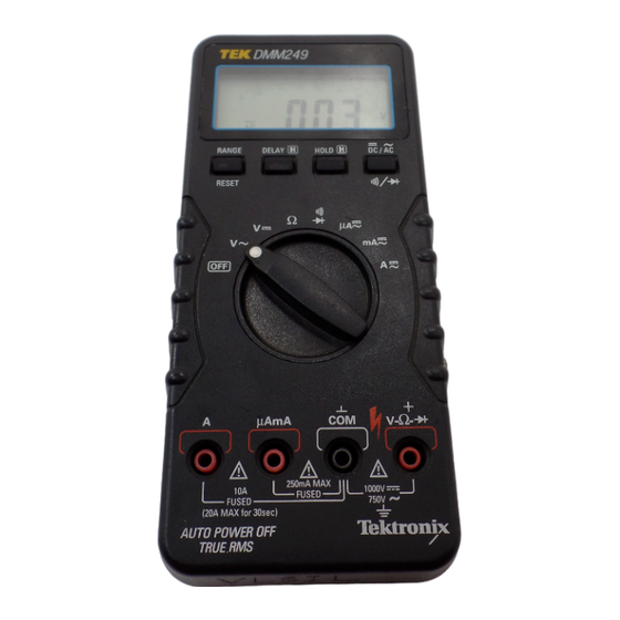
- Page 4 DMM249 Digital Multimeter The DMM249 is a rugged, handheld digital multimeter that allows you to make accurate measurements quickly and easily. Whether you are a professional or hobbyist, this instrument provides a useful range of features. 3200 count display with bargraph...
- Page 5 DMM249 Digital Multimeter Handheld Instruments Basic Service...
- Page 6 750 VAC 600 VDC/AC A connector 15 A (600 V) fast blow fuse (type KTK or KLK) Tektronix part number 159-0287-00 mA/mA connector 1 A (600 V) fast blow fuse (type BLS or BBS) Tektronix part number 159-0337-00 TL60 test lead set Rated 1000 V ANSI/ISA S82.02-1988...
- Page 7 DMM249 Specifications Table 1: General specifications (cont.) Characteristics Description Dimensions (H x W x D) with holster 199 mm x 98 mm x 51 mm Dust/water protection IP 54 Handheld Instruments Basic Service...
- Page 8 DMM249 Specifications Table 2: Measurement characteristics Characteristics Description DC volts Ranges 300 mV, 3 V, 30 V, 300 V, 1000 V Accuracy ±(0.3% reading + 2 digits) Input impedance 10 MW Resolution (by range) 300 mV 100 mV 1 mV...
- Page 9 DMM249 Specifications Table 2: Measurement characteristics (cont.) Characteristics Description Resolution (by range) 300 mA 0.1 mA 3 mA 1 mA 30 mA 10 mA 300 mA 0.1 mA 20 A 10 mA AC current Ranges 300 mA, 3 mA, 30 mA, 300 mA, 20 A...
- Page 10 DMM249 Specifications Table 2: Measurement characteristics (cont.) Characteristics Description Resolution (by range) 300 W 0.1 W 3 kW 30 kW 10 W 300 kW 100 W 3 MW 1 kW 30 MW 10 kW Continuity check threshold Approximately 50 W — tone will sound...
- Page 11 H For AC measurements, allow the multimeter to settle to its final value before taking the measurement. H The multimeter remains fully assembled and in the holster. The DMM249 performance verification consists of the checks listed in Table 4. Table 4: Performance verification checks AC Volts Check...
- Page 12 DMM249 Performance Verification Test Equipment The performance verification procedures use external traceable test equipment to directly check warranted characteristics. Alternative test equipment must meet or exceed the intended minimum requirements specified in Table 5. If you substitute equipment, you may need to modify the procedures.
- Page 13 DMM249 Performance Verification Set Up To prepare for the performance verification checks, do the following steps. 1. Allow the multimeter to stabilize at the ambient temperature for one hour before testing. 2. Turn the multimeter on by rotating the function switch to any position other than OFF.
-
Page 14: Verification Procedure
DMM249 Performance Verification Verification Procedure Implement the following checks to verify the performance of your DMM249 multimeter. WARNING . To avoid electric shock, avoid touching exposed connections. AC Volts Check Perform the following steps to verify the AC voltage measurement accuracy. - Page 15 DMM249 Performance Verification W Check Perform the following steps to verify the resistance measurement accuracy in W mode. 1. Set the multimeter dial to W. 2. Connect the calibrator outputs to the multimeter V-W- and COM input connectors. 3. Set the calibrator to each of the values in the W test record and verify that the multimeter reads within the specified Display minimum and maximum limits.
- Page 16 DMM249 Performance Verification AC Microampere Check Perform the following steps to verify the AC microampere measurement accuracy. 1. Set the multimeter dial to mA . 2. Push the DC/AC button to select AC mode. 3. Connect the calibrator outputs to the multimeter mAmA and COM input connectors.
- Page 17 DMM249 Performance Verification DC Ampere Check Perform the following steps to verify the DC ampere measurement accuracy. 1. Set the multimeter dial to A . 2. Connect the calibrator outputs to the multimeter A and COM input connec- tors. 3. Set the calibrator to each of the values in the DC ampere test record and verify that the multimeter reads within the specified Display minimum and maximum limits.
- Page 18 DMM249 Performance Verification Handheld Instruments Basic Service...
- Page 19 DMM249 Performance Verification DMM249 Test Record Serial number Procedure performed by Date DMM249 test record Test input Tolerance Display minimum Reading Display maximum AC volts test 2.900 V 50 Hz ±1.3% + 3 counts 2.859 V 2.940 V 300 Hz ±1.3% + 3 counts...
- Page 20 DMM249 Performance Verification DMM249 test record (cont.) Test input Tolerance Display minimum Reading Display maximum Continuity test 0.0 W Beeper sounds 100 W Beeper does not sound Multimeter leads shorted Beeper sounds DC microampere test 0.0 mA ±2 counts –00.2 mA 00.2 mA...
-
Page 21: List Of Adjustments
The procedures in this section do not verify performance. To confirm that your multimeter meets factory specifications, perform the procedures in the DMM249 Performance Verification section. List of Adjustments Use the adjustments listed in Table 6 to return DMM249 multimeter to factory calibration. Table 6: DMM249 adjustments DC Volts... -
Page 22: Preparation For Adjustment
DMM249 Adjustment Procedures Preparation for Adjustment The following guidelines apply to all DMM249 adjustments: H Perform all adjustments in a 21_ to 25_ C ambient environment with a relative humidity of 75% or less. H Warm up the multimeter for at least 15 minutes. - Page 23 DMM249 Adjustment Procedures Adjustments The procedures within this section use the adjustments accessible with the back case removed from the multimeter. Figure 2: Adjustment locations DC Volts Perform the following steps to adjust the DC voltage calibration. 1. Set the multimeter dial to V .
- Page 24 DMM249 Adjustment Procedures Reassembling the Multimeter 1. Ensure that the rotary dial is properly aligned. 2. Align the tabs of the bottom case half with the slots in the top case half at the end of the meter near the input connectors.
Need help?
Do you have a question about the DMM249 and is the answer not in the manual?
Questions and answers