Table of Contents
Advertisement
Quick Links
Advertisement
Table of Contents

Related Manuals for Tektronix Keithley DMM6500


Summary of Contents for Tektronix Keithley DMM6500
- Page 1 Model DMM6500 Quick Start Guide...
-
Page 2: Safety Precautions
require protection for high transient overvoltages often associated with local AC mains Safety precautions connections. Certain Keithley measuring instruments may be connected to mains. The following safety precautions should be observed before using this product and These instruments will be marked as category II or higher. any associated instrumentation. - Page 3 in personal injury or death. Always read the associated information very carefully Do not touch any object that could provide a current path to the common side of the before performing the indicated procedure. circuit under test or power line (earth) ground. Always make measurements with dry The CAUTION heading in the user documentation explains hazards that could hands while standing on a dry, insulated surface capable of withstanding the voltage damage the instrument.
- Page 4 Power and environmental specifications For indoor use only. Power supply 50 Hz to 60 Hz and 400 Hz, the line frequency voltage is automatically sensed at power-up Maximum VA 50 VA Operating Maximum 2000 m (6562 ft) above sea level altitude Operating 0 °C to 50 °C, 80% relative humidity at 35 °C...
-
Page 5: Contact Information
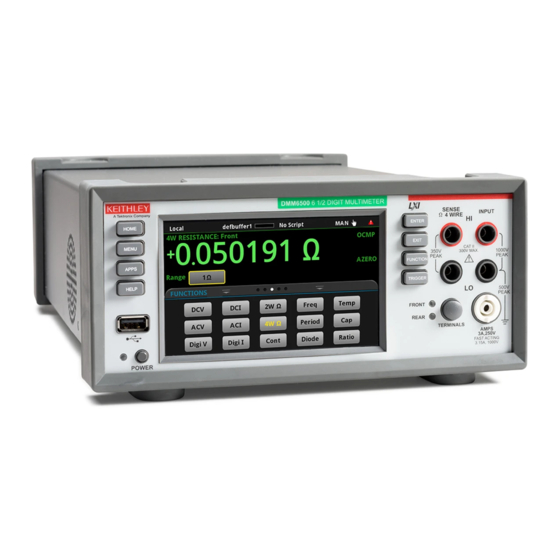
DMM functions with high-speed digitizing and large graphical color touchscreen You can also call the Tektronix corporate headquarters (toll- display. This DMM offers a broad range of measurement free inside the U.S. and Canada only) at 1-800-833-9200. -
Page 6: Unpack And Inspect The Instrument
Unpack and inspect the instrument You should have received the DMM6500 with: USB Type B cable To unpack and inspect the instrument: Power-line cord 1757 Standard Test Lead Kit Inspect the box for damage. Software and Documentation Downloads document and Open the box. - Page 7 Check fuse settings The fuse is set at the factory. Check the power module on the back of the instrument. The correct voltage setting should be displayed. To change the fuse orientation: Make sure the POWER is off. Remove all test leads connected to the instrument. Remove the power cord.
-
Page 8: Connect The Instrument
Connect the instrument • Read and comply with the specifications of all instruments in the system. The overall allowed signal levels may be constrained by the lowest rated instrument Important test system safety information in the system. For example, if you are using a 500 V This product is sold as a stand-alone instrument that may power supply with a 300 V dc rated switch, the maximum become part of a system that could contain hazardous... - Page 9 • Where possible, use automatic handlers so operators are not required to access the DUT or other potentially hazardous areas. • Provide training to all users of the system so they understand all potential hazards and know how to protect themselves from injury.
-
Page 10: Install The Instrument
Install the instrument The power cord supplied with the DMM6500 contains a You can use the DMM6500 on a bench or in a rack. If separate protective earth (safety ground) wire for use you are installing the DMM6500 in a rack, please see the with grounded outlets. - Page 11 To connect the power cord: Connect the supplied power cord to the AC receptacle on the rear panel. Connect the power cord to a grounded AC outlet. To turn a DMM6500 on: Disconnect any devices under test (DUTs) from the DMM6500.
- Page 12 Selects Displays the highlighted home screen choice DMM6500 6 1/2 DIGIT MULTIMETER SENSE INPUT Opens the Ω 4 WIRE HI HI Returns to main menu previous screen CAT II 350V 1000VDC 300V MAX. PEAK 750VAC Opens the Selects 500V PEAK apps manager measurement FRONT...
- Page 13 Optional KTTI Ethernet port interface card slot AMPS 10A, 250V Trigger terminals USB Type B port AMPS 3A, 250V LO terminal Fuse module Scanner Power module HI terminal Input fuse card slot Explore...
-
Page 14: Connections For Testing
Connections for testing To make connections: The physical connections for the front panel are shown in the following figure. Note that you must use either the front terminals or rear terminals—you cannot mix connections. To prevent electric shock, test connections must be The front-panel and rear-panel connections are safety configured such that the user cannot come in contact banana jacks. -
Page 15: Verify Measurement Operation
For this example, you can make the connections with the The voltage measurements appear in the DC Model 1757 Standard Test Lead Kit. VOLTAGE area of the home screen and should read approximately 0 V. To make connections: Make sure the front-panel POWER switch is off. To view measurements on the graph screen: Connect the red lead to the INPUT HI connection. -
Page 16: Where Can I Find Updated Drivers
FAQs Is there any software to help me get started? Yes. KickStart and TestScript Builder can help you get Where can I find updated drivers? started with the DMM6500. For the latest drivers and additional support information, see KickStart is a software program that allows you to set the Keithley Instruments support website. - Page 17 How do I change the command set? To set the command set from the front panel: Press the MENU key. You can change the command set that you use with the Under System, select Settings. DMM6500. The command sets that are available include: Select Command Set.
-
Page 18: Why Did My Settings Change
How do I save the present state of the instrument? Why did my settings change? You can save the settings in the instrument as a script using Many of the commands in the DMM6500 are saved with the front-panel menus or from a remote interface. After they the measure function that was active when you set them. - Page 19 Next steps Additional information This manual has prepared you to start using your new DMM6500 Multimeter for your application. For more detailed information, refer to the Keithley Instruments Model DMM6500 Reference Manual. Also see tek.com/keithley for support and additional information about the instrument. From the website, you can access: •...
- Page 20 Contact information: 1-800-833-9200 For additional contacts, see tek.com/contact-tek Find more valuable resources at TEK.COM. Copyright © 2023, Tektronix. All rights reserved. Tektronix products are covered by U.S. and foreign patents, issued and pending. Information in this publication supersedes that in all previously published material.
Need help?
Do you have a question about the Keithley DMM6500 and is the answer not in the manual?
Questions and answers