Table of Contents
Advertisement
Quick Links
Advertisement
Table of Contents

Related Manuals for Tektronix KEITHLEY DMM6500


Summary of Contents for Tektronix KEITHLEY DMM6500
- Page 1 DMM6500 6½-Digit Multimeter with Scanning Calibration and Adjustment Manual...
- Page 2 © 2021, Keithley Instruments, LLC Cleveland, Ohio, U.S.A. All rights reserved. Any unauthorized reproduction, photocopy, or use of the information herein, in whole or in part, without the prior written approval of Keithley Instruments, LLC, is strictly prohibited. These are the original instructions in English. and TSP-Link are trademarks of Keithley Instruments, LLC.
- Page 3 Safety precautions The following safety precautions should be observed before using this product and any associated instrumentation. Although some instruments and accessories would normally be used with nonhazardous voltages, there are situations where hazardous conditions may be present. This product is intended for use by personnel who recognize shock hazards and are familiar with the safety precautions required to avoid possible injury.
- Page 4 For safety, instruments and accessories must be used in accordance with the operating instructions. If the instruments or accessories are used in a manner not specified in the operating instructions, the protection provided by the equipment may be impaired. Do not exceed the maximum signal levels of the instruments and accessories. Maximum signal levels are defined in the specifications and operating information and shown on the instrument panels, test fixture panels, and switching cards.
-
Page 7: Table Of Contents
Table of contents Introduction ......................1-1 Welcome ..........................1-1 Introduction to this manual ....................1-1 Extended warranty ....................... 1-2 Contact information ......................1-2 Performance verification ..................2-1 Introduction .......................... 2-1 Verification test requirements ....................2-2 Environmental conditions ......................2-2 Warmup period .......................... 2-2 Line power.......................... - Page 8 Table of contents DMM6500 6½-Digit Multimeter with Scanning Calibration and Adjustment Manual General adjustment considerations ..................3-4 Initial instrument setup ......................3-5 Select the correct terminals ....................... 3-5 Select the TSP command set ....................3-5 Verify instrument date and time ....................3-6 Set up remote connections......................
-
Page 9: Introduction
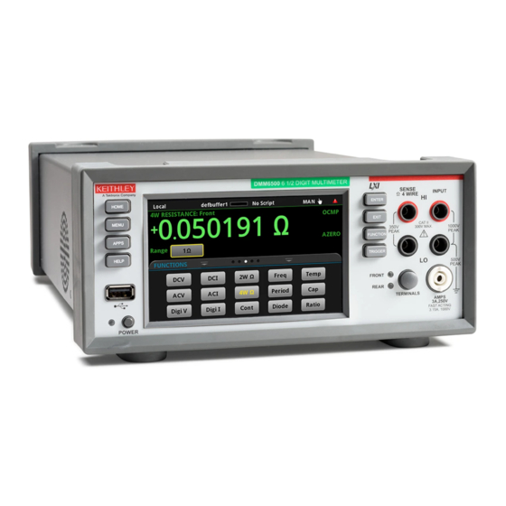
Section 1 Introduction In this section: Welcome .................. 1-1 Introduction to this manual ............1-1 Extended warranty ..............1-2 Contact information ..............1-2 Welcome The DMM6500 is a 6½ digit graphical sampling multimeter that expands standard DMM functions with high-speed digitizing and large graphical color touchscreen display. This manual provides information on completing verification and adjustment procedures for your DMM6500. -
Page 10: Extended Warranty
If you have any questions after you review the information in this documentation, please contact your local Keithley Instruments office, sales partner, or distributor. You can also call the Tektronix corporate headquarters (toll-free inside the U.S. and Canada only) at 1-800-833-9200. For worldwide contact numbers, visit tek.com/contact-us. -
Page 11: Performance Verification
Section 2 Performance verification In this section: Introduction ................2-1 Verification test requirements ........... 2-2 Calibration verification limits ............. 2-4 Performing the verification test procedures ......2-5 Front-panel calibration verification ........... 2-6 Rear-panel verification ............2-46 Introduction Use the procedures in this section to verify that DMM6500 accuracy is within the limits stated in the instrument’s one-year accuracy specifications. -
Page 12: Verification Test Requirements
If the instrument is still under warranty and its performance is outside specified limits, please contact your local Keithley Instruments office, sales partner, or distributor. You can also call the Tektronix corporate headquarters (toll-free inside the U.S. and Canada only) at 1-800-833-9200. For worldwide contact numbers, visit tek.com/contact-us. -
Page 13: Line Power
DMM6500 6½-Digit Multimeter with Scanning Calibration and Adjustment Manual Section 2: Performance verification Line power The DMM6500 requires a line voltage of 100 V to 240 V and a line frequency of 400 Hz, 50 Hz or 60 Hz. Calibration verification tests should be performed within this range. The instrument automatically senses the line frequency at power-up. -
Page 14: Calibration Verification Limits
Section 2: Performance verification DMM6500 6½-Digit Multimeter with Scanning Calibration and Adjustment Manual Calibration verification limits The calibration verification limits stated in this section have been calculated using only the DMM6500 one-year accuracy specifications and ambient temperature ±5 °C from T (the temperature at which the instrument was calibrated). -
Page 15: Performing The Verification Test Procedures
DMM6500 6½-Digit Multimeter with Scanning Calibration and Adjustment Manual Section 2: Performance verification Performing the verification test procedures The following topics provide a summary of calibration verification test procedures and items to consider before performing any calibration verification test. Test summary Front-panel tests: •... -
Page 16: Test Considerations
Section 2: Performance verification DMM6500 6½-Digit Multimeter with Scanning Calibration and Adjustment Manual Test considerations When performing the calibration verification procedures: • Be sure to restore factory front-panel defaults. From the front panel, select the MENU key, select Info/Manage, and select System Reset. •... - Page 17 DMM6500 6½-Digit Multimeter with Scanning Calibration and Adjustment Manual Section 2: Performance verification Verify dc voltage accuracy for the 100 mV to 1000 V ranges To verify 100 mV to 1000 V dc voltage accuracies, you will: • Apply accurate dc voltages from the calibrator to the DMM6500 front-panel terminals. •...
- Page 18 Section 2: Performance verification DMM6500 6½-Digit Multimeter with Scanning Calibration and Adjustment Manual 2. On the DMM6500, press the FUNCTION key and select DC voltage. 3. On the home screen, select the button next to Range and select 100 mV. 4.
- Page 19 DMM6500 6½-Digit Multimeter with Scanning Calibration and Adjustment Manual Section 2: Performance verification Verify the dc voltage 100 V range The information in this section is intended for qualified service personnel only, as described by the types of product users in the Safety precautions pages, provided at the beginning of this document.
-
Page 20: Ac Voltage Verification
Section 2: Performance verification DMM6500 6½-Digit Multimeter with Scanning Calibration and Adjustment Manual AC voltage verification To verify ac voltage accuracy: • For the 100 mV to 100 V ranges, apply accurate voltages from the calibrator to the DMM6500 front-panel terminals. •... - Page 21 DMM6500 6½-Digit Multimeter with Scanning Calibration and Adjustment Manual Section 2: Performance verification To verify ac voltage accuracy: 1. Connect the DMM6500 HI and LO INPUT connectors to the calibrator as shown in the following figure. Figure 2: Connections for ac voltage verification 100 mV to 100 V ranges 2.
- Page 22 Section 2: Performance verification DMM6500 6½-Digit Multimeter with Scanning Calibration and Adjustment Manual Verify the ac voltage 100 mV range Nominal value Frequency Lower limit Upper limit 20 Hz 99.91 100.09 1 kHz 99.91 100.09 50 kHz 99.83 100.17 100 kHz 99.32 100.68 Verify the ac voltage 1 V range...
- Page 23 DMM6500 6½-Digit Multimeter with Scanning Calibration and Adjustment Manual Section 2: Performance verification To verify ac voltage accuracy for the 750 V range: 1. Put the calibrator in Standby. 2. Connect the DMM6500 HI and LO INPUT connectors to the calibrator as shown in the following figure.
-
Page 24: Digitize Dc Voltage Verification
Section 2: Performance verification DMM6500 6½-Digit Multimeter with Scanning Calibration and Adjustment Manual 9. Set the calibrator to OPERATE. 10. Source ac voltages for each of the frequencies listed in the "Verify the ac voltage 750 V range" table, below. Be sure that the readings are within low and high limits. Verify the ac voltage 750 V range Nominal value Frequency... - Page 25 DMM6500 6½-Digit Multimeter with Scanning Calibration and Adjustment Manual Section 2: Performance verification To verify digitize voltage accuracy: 1. Connect the DMM6500 HI and LO INPUT connectors to the calibrator as shown in the following figure. Figure 4: Connections for digitize voltage verification 100 mV to 1000 V ranges 2.
- Page 26 Section 2: Performance verification DMM6500 6½-Digit Multimeter with Scanning Calibration and Adjustment Manual Verify the digitize voltage 100 mV range Description Nominal value Lower limit Upper limit Full scale (+) 99.94 100.06 Half scale (+) 49.95 50.05 Half scale (–) -50.05 -49.95 Full scale (–)
-
Page 27: Frequency Verification
DMM6500 6½-Digit Multimeter with Scanning Calibration and Adjustment Manual Section 2: Performance verification Frequency verification To verify frequency accuracy, you will: • Apply accurate frequencies from the function generator to the terminals on the front panel of the DMM6500. • Verify that the displayed readings are within specified limits. -
Page 28: Simulated Thermocouple Type J Temperature Verification
Section 2: Performance verification DMM6500 6½-Digit Multimeter with Scanning Calibration and Adjustment Manual Verify the frequency Use the following values to verify the performance of the DMM6500. Actual values depend on published specifications (see Example reading limit calculation (on page 2-4)). Description Frequency (Hz) Lower limit (Hz) - Page 29 DMM6500 6½-Digit Multimeter with Scanning Calibration and Adjustment Manual Section 2: Performance verification To verify the simulated thermocouple type J temperature: 1. Connect the DMM6500 HI and LO INPUT terminals to the calibrator HI and LO terminals as shown in the following figure. Figure 6: Connections for thermocouple verification DMM6500-905-01 Rev.
- Page 30 Section 2: Performance verification DMM6500 6½-Digit Multimeter with Scanning Calibration and Adjustment Manual 2. On the DMM6500, press the FUNCTION key and select DC voltage. 3. Press the MENU key. 4. Under Measure, select Settings. 5. Set the range to 100 mV. 6.
-
Page 31: Simulated Rtd Temperature Verification
DMM6500 6½-Digit Multimeter with Scanning Calibration and Adjustment Manual Section 2: Performance verification Simulated Uncompensated Lower limit Upper limit temperature calibrator source value (V) –190 °C –7.659 mV –190.2 °C –189.8 °C 0 °C 0.000 mV –0.2 °C 0.2 °C 750 °C 42.281 mV 749.8 °C... - Page 32 Section 2: Performance verification DMM6500 6½-Digit Multimeter with Scanning Calibration and Adjustment Manual Equation for 0 °C to 850 °C temperature range (1 + AT + BT where: • is the calculated resistance of the RTD • is the known RTD resistance at 0 °C •...
- Page 33 DMM6500 6½-Digit Multimeter with Scanning Calibration and Adjustment Manual Section 2: Performance verification Verify the simulated RTD temperature Use the values in the tables following the steps below to verify the performance of the DMM6500. Actual values depend on the published specifications (see Example reading limit calculation (on page 2-4)).
- Page 34 Section 2: Performance verification DMM6500 6½-Digit Multimeter with Scanning Calibration and Adjustment Manual 2. For 3-wire accuracy, connect the DMM6500 INPUT and SENSE terminals to the calibrator as shown in the following figure. The SENSE HI wire is not required for 3-wire RTD measurements. For 3-wire RTD, accuracy is for <...
-
Page 35: Resistance Verification
DMM6500 6½-Digit Multimeter with Scanning Calibration and Adjustment Manual Section 2: Performance verification 14. Repeat for 100 Ω and 190 Ω source values. Example PT100 1.000000E+02 3.850550E-03 alpha 1.086300E-01 beta 1.499900E+00 delta 3.908304E-03 -5.775440E-07 -4.182852E-12 4-wire RTD 3-wire RTD Nominal Actual calibrator Temperature ±0.06 °C accuracy... - Page 36 Section 2: Performance verification DMM6500 6½-Digit Multimeter with Scanning Calibration and Adjustment Manual To verify 4-wire resistance accuracy: 1. Connect the DMM6500 INPUT and SENSE terminals to the calibrator as shown in the following figure. Figure 9: Connections for 4-wire resistance accuracy verification 2.
- Page 37 DMM6500 6½-Digit Multimeter with Scanning Calibration and Adjustment Manual Section 2: Performance verification You can use either the front-panel controls or remote interface commands to set measurement parameters for verification. For calibration, you must use remote interface commands. The example below is an example of remote interface commands that will generate event messages.
- Page 38 Section 2: Performance verification DMM6500 6½-Digit Multimeter with Scanning Calibration and Adjustment Manual Four-wire resistance verification with offset compensation off The values and limits in the following tables are for example only. You must calculate test limits based on the actual resistance values output by your calibrator or resistance source (see Example reading limit calculation (on page 2-4)).
- Page 39 DMM6500 6½-Digit Multimeter with Scanning Calibration and Adjustment Manual Section 2: Performance verification Figure 10: Connections for 100 MΩ verification 2. Set the calibrator for 2-wire resistance with external sense off. 3. On the DMM6500, press the FUNCTION key and select 2W Res. 4.
-
Page 40: Dc Current Verification
Section 2: Performance verification DMM6500 6½-Digit Multimeter with Scanning Calibration and Adjustment Manual DC current verification The DMM6500 dc current ranges can be verified using several methods, depending on the level of measurement uncertainty required. This manual describes the verification procedure using a Fluke 8508A or 8588A reference digital multimeter (DMM) in series with the DMM6500 to determine the nominal test current value for the 10 µA to 100 mA ranges. - Page 41 DMM6500 6½-Digit Multimeter with Scanning Calibration and Adjustment Manual Section 2: Performance verification To prepare the DMM6500 for dc current accuracy verification: 1. Set up the DMM6500 for dc current and the range being tested. Make sure relative offset is disabled.
- Page 42 Section 2: Performance verification DMM6500 6½-Digit Multimeter with Scanning Calibration and Adjustment Manual To verify DMM6500 accuracy for each range: 1. Set the calibrator to source zero current. 2. Set the reference DMM to DC Current and select the appropriate range to be verified. Use the Model 8508A or 8588A 200 µA range to verify the DMM6500 10 µA and 100 µA ranges.
- Page 43 DMM6500 6½-Digit Multimeter with Scanning Calibration and Adjustment Manual Section 2: Performance verification Range Nominal Specification Range Nominal Specification input (µA) tolerance (µA) (based input (µA) tolerance (µA) on nominal) (based on nominal) 1 mA 0.000500 10 mA 0.00250 0.000275 0.00150 –0.5 0.000275...
- Page 44 Section 2: Performance verification DMM6500 6½-Digit Multimeter with Scanning Calibration and Adjustment Manual Zero verify the DMM6500: 1. On the calibrator, select the OPR/STBY key. Make sure that the front panel displays STANDBY. 2. Set the ranges to 100 mA. 3.
-
Page 45: Digitize Current Verification
DMM6500 6½-Digit Multimeter with Scanning Calibration and Adjustment Manual Section 2: Performance verification Digitize current verification The following topics describe how to verify digitized dc current on the DMM6500. Verify digitize current 100 µA to 3 A ranges To verify digitize dc current accuracy: 1. - Page 46 Section 2: Performance verification DMM6500 6½-Digit Multimeter with Scanning Calibration and Adjustment Manual Verify digitize current 100 µA range Description Calibrator setpoint Lower limit Upper limit Full scale (+) 99.998 99.878 100.118 Half scale (+) 49.9991 49.9141 50.0841 Half scale (–) -49.993 -50.0843 -49.9143...
-
Page 47: Ac Current Verification
DMM6500 6½-Digit Multimeter with Scanning Calibration and Adjustment Manual Section 2: Performance verification Verify digitize current 1 A range Description Calibrator setpoint Lower limit Upper limit Full scale (+) 0.999 1.001 Half scale (+) 0.49935 0.50065 Half scale (–) –0.5 -0.50065 -0.49935 Full scale (–) - Page 48 Section 2: Performance verification DMM6500 6½-Digit Multimeter with Scanning Calibration and Adjustment Manual Verify ac current on the 100 µA to 3 A ranges To verify ac current accuracy, you will: • Apply accurate voltages from the Fluke 5720A or 5730A multifunction calibrator to the DMM6500 front-panel terminals.
- Page 49 DMM6500 6½-Digit Multimeter with Scanning Calibration and Adjustment Manual Section 2: Performance verification 7. Connect the DMM6500 to the calibrator as shown in the following figure. Figure 14: Connections for ac current verification 8. Source ac current for each of the frequencies listed in the following tables. 9.
- Page 50 Section 2: Performance verification DMM6500 6½-Digit Multimeter with Scanning Calibration and Adjustment Manual Verify ac current 100 mA range Description Verification point Lower limit Upper limit 100 mA at 40 Hz 99.86 100.14 100 mA at 1 kHz 99.86 100.14 100 mA at 4.9 kHz 99.86 100.14...
-
Page 51: Capacitance Verification
DMM6500 6½-Digit Multimeter with Scanning Calibration and Adjustment Manual Section 2: Performance verification Capacitance verification To compensate for capacitance offset of the cable and 1 µF thru 100 µF decade box: 1. Connect the DMM6500, shielded banana cable, banana to dual BNC cable, and 1 µF through 100 µF decade capacitor box as shown in the following diagram. - Page 52 Section 2: Performance verification DMM6500 6½-Digit Multimeter with Scanning Calibration and Adjustment Manual 2. Set the decade capacitor box to 0 F. 3. On the DMM6500, press the FUNCTION key, select the Measure Functions tab, and select Capacitance. 4. Press the MENU key. 5.
- Page 53 DMM6500 6½-Digit Multimeter with Scanning Calibration and Adjustment Manual Section 2: Performance verification 9. Connect the shielded banana cable to the 1 nF to 1 µF Decade Capacitance Box as shown in the figure below. Figure 16: Capacitance verification connections 10.
-
Page 54: Verifying Zero Values Using A 4-Wire Short
Section 2: Performance verification DMM6500 6½-Digit Multimeter with Scanning Calibration and Adjustment Manual Verify the capacitance Description Verification point Lower limit (F) Upper limit (F) 1 nF range cable REL 0.375 0.25 10% 1 nF range 0.0942 0.1058 70% 1 nF range 0.6894 0.7106 10% 10 nF range... - Page 55 DMM6500 6½-Digit Multimeter with Scanning Calibration and Adjustment Manual Section 2: Performance verification Verify resistance zero values using a 4-wire short To verify resistance zero values: 1. Select the 4W Res function. 2. Set the DMM6500 to the 1Ω range. 3.
-
Page 56: Rear-Panel Verification
Section 2: Performance verification DMM6500 6½-Digit Multimeter with Scanning Calibration and Adjustment Manual Verify dc voltage zero values using the 4-wire short To verify dc voltage zero values: 1. Leave the short connected as described in Verify resistance zero values using a 4-wire short page 2-45). -
Page 57: Dc Current 10 A Range Verification
DMM6500 6½-Digit Multimeter with Scanning Calibration and Adjustment Manual Section 2: Performance verification DC current 10 A range verification To verify 10 A range: 1. Set the TERMINALS switch to REAR. 2. Press the FUNCTION key and select DC Current. 3. - Page 58 Section 2: Performance verification DMM6500 6½-Digit Multimeter with Scanning Calibration and Adjustment Manual Apply a relative offset to the DMM6500: 1. On the calibrator, select the OPR/STBY key. Ensure that the front panel displays STANDBY. 2. Verify the DMM6500 zero reading. 3.
-
Page 59: Digitize Current 10 A Range Verification
DMM6500 6½-Digit Multimeter with Scanning Calibration and Adjustment Manual Section 2: Performance verification Digitize current 10 A range verification Ensure cabling is designed to conduct 10 A without significant voltage drop. In general, cables for the 10 A range steps should be made of heavy gauge wire and should be as short as practical. - Page 60 Section 2: Performance verification DMM6500 6½-Digit Multimeter with Scanning Calibration and Adjustment Manual 2. Set the TERMINALS switch to REAR. 3. Press the FUNCTION key, select the Digitize Functions tab, and select Digitize Current. 4. Press the HOME key. 5. Set the range to 10A. 6.
-
Page 61: Ac Current 10 A Verification
DMM6500 6½-Digit Multimeter with Scanning Calibration and Adjustment Manual Section 2: Performance verification AC current 10 A verification Verify that the displayed readings are within specified limits. Use the values in the tables following the steps below to verify the performance of the DMM6500. Actual values depend on the published specifications (see Example reading limit calculation (on page... - Page 62 Section 2: Performance verification DMM6500 6½-Digit Multimeter with Scanning Calibration and Adjustment Manual 8. Connect the DMM6500 to the calibrator and amplifier as shown in the following figure. Ensure cabling is designed to conduct 10 A without significant voltage drop. In general, cables for the 10 A range steps should be made of heavy gauge wire and should be as short as practical.
- Page 63 DMM6500 6½-Digit Multimeter with Scanning Calibration and Adjustment Manual Section 2: Performance verification Verify ac current 10 A range Description Verification point Lower limit Upper limit 40 Hz 9.954 10.046 1 kHz 9.954 10.046 4.9 kHz 9.954 10.046 DMM6500-905-01 Rev. E June 2021 2-53...
-
Page 65: Adjustment
Section 3 Adjustment In this section: Introduction ................3-1 Environmental conditions ............3-2 Warmup period ................. 3-2 Adjustment overview ..............3-3 Recommended test equipment ..........3-3 General adjustment considerations .......... 3-4 Initial instrument setup ............. 3-5 Remote calibration adjustment procedures ......3-7 Enable temperature correction .......... -
Page 66: Environmental Conditions
Section 3: Adjustment DMM6500 6½-Digit Multimeter with Scanning Calibration and Adjustment Manual Environmental conditions To make sure you get accurate results, the environment must meet the following conditions. Temperature and relative humidity Conduct the adjustment procedures in a test environment with: •... -
Page 67: Adjustment Overview
DMM6500 6½-Digit Multimeter with Scanning Calibration and Adjustment Manual Section 3: Adjustment Adjustment overview DMM6500 adjustment is performed using a remote connection through either an optional GPIB, LAN, or USB interface. The calibration adjustment commands provided in this manual use the Test Script Processor (TSP ) command language. -
Page 68: General Adjustment Considerations
Section 3: Adjustment DMM6500 6½-Digit Multimeter with Scanning Calibration and Adjustment Manual General adjustment considerations • DMM6500 dc voltage performance is sensitive to errors from thermoelectric potentials generated by test cables and connections. Be sure to use high-quality cables and connection techniques. When changing a connection during the adjustment process, be sure to allow time (up to five minutes) for thermal settling. -
Page 69: Initial Instrument Setup
DMM6500 6½-Digit Multimeter with Scanning Calibration and Adjustment Manual Section 3: Adjustment Initial instrument setup Before adjusting calibration, make sure that the instrument is set up: • For remote operation and TSP commands. • To the correct date and time. You must also unlock calibration. -
Page 70: Verify Instrument Date And Time
Section 3: Adjustment DMM6500 6½-Digit Multimeter with Scanning Calibration and Adjustment Manual Verify instrument date and time Before adjusting calibration, verify the system date of the DMM6500. From the front panel: 1. Press the MENU key. 2. Under System, select Settings. The SYSTEM SETTINGS menu opens. 3. -
Page 71: Disable Temperature Correction
DMM6500 6½-Digit Multimeter with Scanning Calibration and Adjustment Manual Section 3: Adjustment Disable temperature correction Even though temperature correction does not affect calibration, it must be disabled while calibration is being performed. cal.adjust.step.setup("TC_EN") cal.adjust.step.execute("TC_EN", 0) Remote calibration adjustment procedures The front-panel display does not show calibration progress or completion. The following sections provide the preparation and command parameters that you need to complete adjustments to you DMM6500. - Page 72 Section 3: Adjustment DMM6500 6½-Digit Multimeter with Scanning Calibration and Adjustment Manual Prepare your DMM6500 for a front-terminal adjustment with a 4-wire short To prepare the DMM6500 for a front-terminal adjustment with a 4-wire short: 1. Set the TERMINALS switch to FRONT. 2.
- Page 73 DMM6500 6½-Digit Multimeter with Scanning Calibration and Adjustment Manual Section 3: Adjustment Command parameters for a front-terminal adjustment with a 4-wire short When calibrating your DMM6500 for a front-terminal adjustment with a 4-wire short, use the following command parameters. Send each command parameter twice. First, send the parameter using the setup command. Second, send the parameter using the execute command.
-
Page 74: Rear-Terminal Adjustment With A 4-Wire Short
Section 3: Adjustment DMM6500 6½-Digit Multimeter with Scanning Calibration and Adjustment Manual cal_3W_100kohm_SLO_zero_front cal_4W_100kohm_zero_front cal_2W_1Mohm_zero_front cal_4W_1Mohm_zero_front cal_2W_HiOhm_zero_front cal_4W_HiOhm_zero_front cal_4W_HiOhm_zero_sense cal_diode_10mA_zero_front cal_diode_1mA_zero_front cal_diode_100uA_zero_front cal_diode_10uA_zero_front cal_ACV_1V_zero cal_ACV_10V_zero Rear-terminal adjustment with a 4-wire short The following procedure provides instructions for completing a rear-terminal adjustment using a 4-wire short. - Page 75 DMM6500 6½-Digit Multimeter with Scanning Calibration and Adjustment Manual Section 3: Adjustment Prepare your DMM6500 for a rear-terminal adjustment with a 4-wire short To prepare the DMM6500 for rear-terminal adjustment: 1. Set the TERMINALS switch to REAR. 2. Install the Keithley Model 8610 or 8620 shorting plug on the rear terminals of the DMM6500 as shown in the figure below.
- Page 76 Section 3: Adjustment DMM6500 6½-Digit Multimeter with Scanning Calibration and Adjustment Manual Command parameters for a rear-terminal adjustment with a 4-wire short When calibrating your DMM6500 for a rear-terminal adjustment with a 4-wire short, use the following command parameters. Send each command parameter twice. First, send the parameter using the setup command. Second, send the parameter using the execute command.
-
Page 77: Front-Terminal Adjustment With Open Circuit Inputs
DMM6500 6½-Digit Multimeter with Scanning Calibration and Adjustment Manual Section 3: Adjustment cal_diode_100uA_zero_rear cal_diode_10uA_zero_rear Front-terminal adjustment with open circuit inputs The following procedure provides instructions for completing a front-terminal adjustment with open circuit inputs. The following section provides a command parameter table to complete the adjustment. Prepare your DMM6500 for a front-terminal adjustment with open circuit inputs To prepare the DMM6500 for a front-terminal adjustment with open circuit inputs:... -
Page 78: Rear-Terminal Adjustment With Open Circuit Inputs
Section 3: Adjustment DMM6500 6½-Digit Multimeter with Scanning Calibration and Adjustment Manual Command parameters for a front-terminal adjustment with open circuit inputs When calibrating your DMM6500 for a front-terminal adjustment with open circuit inputs, use the following command parameters. Send each command parameter twice. First, send the parameter using the setup command. Second, send the parameter using the execute command. -
Page 79: Resistance Adjustment
DMM6500 6½-Digit Multimeter with Scanning Calibration and Adjustment Manual Section 3: Adjustment Prepare your DMM6500 for a rear-terminal adjustment with a 4-wire short To prepare the DMM6500 for rear-terminal adjustment: 1. Set the TERMINALS switch to REAR. 2. Remove all connections from the front terminals of your DMM6500. Command parameters for a rear-terminal adjustment with open circuit inputs When calibrating your DMM6500 for a rear-terminal adjustment with open circuit inputs, use the... - Page 80 Section 3: Adjustment DMM6500 6½-Digit Multimeter with Scanning Calibration and Adjustment Manual Prepare your DMM6500 for a resistance adjustment To prepare the DMM6500 for a front-terminal adjustment: 1. Set the TERMINALS switch to FRONT. 2. Connect the DMM6500 to the calibrator as shown in the following figure. Figure 23: Connection for a resistance accuracy adjustment 3.
- Page 81 DMM6500 6½-Digit Multimeter with Scanning Calibration and Adjustment Manual Section 3: Adjustment Command parameters for a resistance adjustment When calibrating your DMM6500 for a resistance adjustment, use the following command parameters. Send each command parameter twice. First, send the parameter using the setup command. Second, send the parameter using the execute command along with the calibrator stimulus value.
-
Page 82: Dc Voltage Adjustment
Section 3: Adjustment DMM6500 6½-Digit Multimeter with Scanning Calibration and Adjustment Manual Command parameters Calibrator Calibrator Calibrator Reference DMM dc function range value current range cal_TS7 cal_4W_10ohm_fs 4-wire Ω actual from calibrator cal_4W_10ohm_OCOMP_fs 4-wire Ω actual from calibrator cal_4W_100ohm_fs 4-wire Ω actual from calibrator cal_4W_100ohm_OCOMP_fs 4-wire Ω... - Page 83 DMM6500 6½-Digit Multimeter with Scanning Calibration and Adjustment Manual Section 3: Adjustment Prepare your DMM6500 for a dc voltage adjustment To prepare the DMM6500 for a dc voltage adjustment: 1. Connect a cable between the calibrator and the DMM6500 as shown in the figure below. Figure 24: Connection for a dc voltage accuracy adjustment 2.
-
Page 84: Dc Current Adjustment
Section 3: Adjustment DMM6500 6½-Digit Multimeter with Scanning Calibration and Adjustment Manual Command parameters for a dc voltage adjustment When calibrating your DMM6500 for a dc voltage adjustment, use the following command parameters. Send each command parameter twice. First, send the parameter using the setup command. Second, send the parameter using the execute command. - Page 85 DMM6500 6½-Digit Multimeter with Scanning Calibration and Adjustment Manual Section 3: Adjustment Prepare your DMM6500 for a dc current adjustment To prepare the DMM6500 for dc current adjustment: Connect the Model DMM6500 to the calibrator as shown in the following figure. Figure 25: Connection for dc current DMM6500-905-01 Rev.
- Page 86 Section 3: Adjustment DMM6500 6½-Digit Multimeter with Scanning Calibration and Adjustment Manual Command parameters for a dc current adjustment When calibrating your DMM6500 for a dc current adjustment, use the following command parameters. Send each command parameter twice. First, send the parameter using the setup command. Second, send the parameter using the execute command along with the calibrator stimulus value.
- Page 87 DMM6500 6½-Digit Multimeter with Scanning Calibration and Adjustment Manual Section 3: Adjustment Command parameters Calibrator Calibrator Calibrator Calibrator Reference function range value stimulus value* DMM dc current range cal_TS6 10 µA range (+) full scale nominal cal_DCI_10uA_fs_pos dc current 0.00022 0.00001 8508A or 8588A 10 µA...
-
Page 88: Dc Current 10 A Range Adjustment
Section 3: Adjustment DMM6500 6½-Digit Multimeter with Scanning Calibration and Adjustment Manual 10 mA range (-) full scale nominal cal_DCI_10mA_fs_neg dc current 0.022 -0.01 8508A or 8588A 10 mA Reading cal_DCI_DIGI_10mA_fs_neg dc current 0.022 -0.01 8508A or 8588A 10 mA Reading *Characterized step measured by the Fluke 8508A or 8588A Command parameters... - Page 89 DMM6500 6½-Digit Multimeter with Scanning Calibration and Adjustment Manual Section 3: Adjustment Prepare your DMM6500 for a dc current 10 A range adjustment To prepare the DMM6500 for dc current adjustment for the 10 A range: Connect the DMM6500 to the calibrator as shown in the following figure using 10 A cables. Figure 26: Connection for a 10 A range adjustment DMM6500-905-01 Rev.
-
Page 90: Ac Voltage Adjustment
Section 3: Adjustment DMM6500 6½-Digit Multimeter with Scanning Calibration and Adjustment Manual Command parameters for a dc current 10 A range adjustment When calibrating your DMM6500 for a dc current 10 A range adjustment, use the following command parameters. Connect a 10 A cable for this adjustment. Send each command parameter twice. - Page 91 DMM6500 6½-Digit Multimeter with Scanning Calibration and Adjustment Manual Section 3: Adjustment Prepare your DMM6500 for an ac voltage adjustment To prepare to run ac adjustments: 1. Set the TERMINALS switch to FRONT. 2. Connect a cable between the calibrator and the DMM6500 as shown in the figure below. Figure 27: Connection for an ac voltage adjustment 3.
- Page 92 Section 3: Adjustment DMM6500 6½-Digit Multimeter with Scanning Calibration and Adjustment Manual Command parameters for an ac voltage adjustment When calibrating your DMM6500 for an ac voltage adjustment, use the following command parameters. Send each command parameter twice. First, send the parameter using the setup command. Second, send the parameter using the execute command.
-
Page 93: Ac Current Adjustment
DMM6500 6½-Digit Multimeter with Scanning Calibration and Adjustment Manual Section 3: Adjustment cal_ACV_700V_1kHz_1pct ac voltage 1 kHz cal_ACV_700V_50kHz_1pct ac voltage 50 kHz cal_ACV_700V_100kHz_1pct ac voltage 100 kHz cal_ACV_700V_200kHz_1pct ac voltage 200 kHz cal_ACV_700V_300kHz_1pct ac voltage 300 kHz cal_ACV_700V_1kHz_fs ac voltage 1100 1 kHz AC current adjustment... - Page 94 Section 3: Adjustment DMM6500 6½-Digit Multimeter with Scanning Calibration and Adjustment Manual Command parameters for an ac current adjustment When calibrating your DMM6500 for an ac current adjustment, use the following command parameters. Send each command parameter twice. First, send the parameter using the setup command. Second, send the parameter using the execute command.
-
Page 95: Ac Current 10 A Range Adjustment
DMM6500 6½-Digit Multimeter with Scanning Calibration and Adjustment Manual Section 3: Adjustment AC current 10 A range adjustment The following procedure provides instructions for completing a front-terminal adjustment ac current in the 10 A range. For this adjustment, you need a Fluke 5720 calibrator. The following section provides a command parameter table to complete the adjustment. -
Page 96: Frequency Adjustment
Section 3: Adjustment DMM6500 6½-Digit Multimeter with Scanning Calibration and Adjustment Manual Command parameters for an ac current 10 A range adjustment When calibrating your DMM6500 for an ac current 10 A range adjustment, use the following command parameters. Send each command parameter twice. First, send the parameter using the setup command. Second, send the parameter using the execute command. - Page 97 DMM6500 6½-Digit Multimeter with Scanning Calibration and Adjustment Manual Section 3: Adjustment Prepare your DMM6500 for a frequency adjustment To prepare the DMM6500 for a frequency adjustment: 1. Connect the Keithley Instruments Model 3390 function generator to the DMM6500 INPUT HI and LO terminals as shown in the following figure.
-
Page 98: Complete List Of Calibration Commands
Section 3: Adjustment DMM6500 6½-Digit Multimeter with Scanning Calibration and Adjustment Manual Command parameters for a frequency adjustment When calibrating your DMM6500 for a frequency adjustment, use the following command parameters. Send each command parameter twice. First, send the parameter using the setup command. Second, send the parameter using the execute command. - Page 99 DMM6500 6½-Digit Multimeter with Scanning Calibration and Adjustment Manual Section 3: Adjustment -- Use front-terminal 4-wire short setup cal.adjust.step.setup("cal_DCV_100mV_zero_front") cal.adjust.step.execute("cal_DCV_100mV_zero_front") -- Use front-terminal 4-wire short setup cal.adjust.step.setup("cal_DCV_DIGI_100mV_zero") cal.adjust.step.execute("cal_DCV_DIGI_100mV_zero") -- Use front-terminal 4-wire short setup cal.adjust.step.setup("cal_DCV_1V_zero_front") cal.adjust.step.execute("cal_DCV_1V_zero_front") -- Use front-terminal 4-wire short setup cal.adjust.step.setup("cal_DCV_DIGI_1V_zero") cal.adjust.step.execute("cal_DCV_DIGI_1V_zero") -- Use front-terminal 4-wire short setup...
- Page 100 Section 3: Adjustment DMM6500 6½-Digit Multimeter with Scanning Calibration and Adjustment Manual -- Use front-terminal 4-wire short setup cal.adjust.step.setup("cal_3W_1kohm_SLO_zero_front") cal.adjust.step.execute("cal_3W_1kohm_SLO_zero_front") -- Use front-terminal 4-wire short setup cal.adjust.step.setup("cal_4W_1kohm_zero_front") cal.adjust.step.execute("cal_4W_1kohm_zero_front") -- Use front-terminal 4-wire short setup cal.adjust.step.setup("cal_2W_10kohm_zero_front") cal.adjust.step.execute("cal_2W_10kohm_zero_front") -- Use front-terminal 4-wire short setup cal.adjust.step.setup("cal_3W_10kohm_zero_front") cal.adjust.step.execute("cal_3W_10kohm_zero_front") -- Use front-terminal 4-wire short setup...
- Page 101 DMM6500 6½-Digit Multimeter with Scanning Calibration and Adjustment Manual Section 3: Adjustment -- Use front-terminal 4-wire short setup cal.adjust.step.setup("cal_ACV_10V_zero") cal.adjust.step.execute("cal_ACV_10V_zero") -- Use rear-terminal 4-wire short setup cal.adjust.step.setup("cal_DCV_100mV_zero_rear") cal.adjust.step.execute("cal_DCV_100mV_zero_rear") -- Use rear-terminal 4-wire short setup cal.adjust.step.setup("cal_DCV_100mV_zero_rear") cal.adjust.step.execute("cal_DCV_100mV_zero_rear") -- Use rear-terminal 4-wire short setup cal.adjust.step.setup("cal_DCV_1V_zero_rear") cal.adjust.step.execute("cal_DCV_1V_zero_rear") -- Use rear-terminal 4-wire short setup...
- Page 102 Section 3: Adjustment DMM6500 6½-Digit Multimeter with Scanning Calibration and Adjustment Manual -- Use rear-terminal 4-wire short setup cal.adjust.step.setup("cal_3W_10kohm_SLO_zero_rear") cal.adjust.step.execute("cal_3W_10kohm_SLO_zero_rear") -- Use rear-terminal 4-wire short setup cal.adjust.step.setup("cal_4W_10kohm_zero_rear") cal.adjust.step.execute("cal_4W_10kohm_zero_rear") -- Use rear-terminal 4-wire short setup cal.adjust.step.setup("cal_2W_100kohm_zero_rear") cal.adjust.step.execute("cal_2W_100kohm_zero_rear") -- Use rear-terminal 4-wire short setup cal.adjust.step.setup("cal_3W_100kohm_SLO_zero_rear") cal.adjust.step.execute("cal_3W_100kohm_SLO_zero_rear") -- Use rear-terminal 4-wire short setup...
- Page 103 DMM6500 6½-Digit Multimeter with Scanning Calibration and Adjustment Manual Section 3: Adjustment -- Use front-terminal 4-wire open circuit setup cal.adjust.step.setup("cal_DCI_10uA_zero_front") cal.adjust.step.execute("cal_DCI_10uA_zero_front") -- Use front-terminal 4-wire open circuit setup cal.adjust.step.setup("cal_DCI_DIGI_3A_zero") cal.adjust.step.execute("cal_DCI_DIGI_3A_zero") -- Use front-terminal 4-wire open circuit setup cal.adjust.step.setup("cal_DCI_DIGI_1A_zero") cal.adjust.step.execute("cal_DCI_DIGI_1A_zero") -- Use front-terminal 4-wire open circuit setup cal.adjust.step.setup("cal_DCI_DIGI_100mA_zero") cal.adjust.step.execute("cal_DCI_DIGI_100mA_zero") -- Use front-terminal 4-wire open circuit setup...
- Page 104 Section 3: Adjustment DMM6500 6½-Digit Multimeter with Scanning Calibration and Adjustment Manual -- Use rear-terminal 4-wire open circuit setup cal.adjust.step.setup("cal_DCI_10uA_zero_rear") cal.adjust.step.execute("cal_DCI_10uA_zero_rear") -- Use resistance setup cal.adjust.step.setup("cal_TS7") cal.adjust.step.execute("cal_TS7") -- Use resistance setup cal.adjust.step.setup("cal_4W_10ohm_fs") cal.adjust.step.execute("cal_4W_10ohm_fs", 10ohm_value_read_from_calibrator) -- Use resistance setup cal.adjust.step.setup("cal_4W_10ohm_OCOMP_fs") cal.adjust.step.execute("cal_4W_10ohm_OCOMP_fs", 10ohm_value_read_from_calibrator) -- Use resistance setup cal.adjust.step.setup("cal_4W_100ohm_fs") cal.adjust.step.execute("cal_4W_100ohm_fs", 100ohm_value_read_from_calibrator)
- Page 105 DMM6500 6½-Digit Multimeter with Scanning Calibration and Adjustment Manual Section 3: Adjustment cal.adjust.step.setup("cal_DCV_DIGI_1kV_fs_pos") cal.adjust.step.setup("cal_DCV_DIGI_1kV_fs_pos") -- Use dc voltage setupcal.adjust.step.setup("cal_DCV_DIGI_1kV_fs_neg") cal.adjust.step.setup("cal_DCV_DIGI_1kV_fs_neg") -- Use dc voltage setup cal.adjust.step.setup("cal_DCV_100V_fs_pos") cal.adjust.step.setup("cal_DCV_100V_fs_pos") -- Use dc voltage setup cal.adjust.step.setup("cal_DCV_DIGI_100V_fs_pos") cal.adjust.step.setup("cal_DCV_DIGI_100V_fs_pos") -- Use dc voltage setup cal.adjust.step.setup("cal_DCV_100V_fs_neg") cal.adjust.step.setup("cal_DCV_100V_fs_neg") -- Use dc voltage setup cal.adjust.step.setup("cal_DCV_DIGI_100V_fs_neg")
- Page 106 Section 3: Adjustment DMM6500 6½-Digit Multimeter with Scanning Calibration and Adjustment Manual cal.adjust.step.execute("cal_DCI_DIGI_100uA_fs_pos",value_read_from_ 8508A/8588A) -- Use dc current setup cal.adjust.step.setup("cal_DCI_100uA_fs_neg") cal.adjust.step.execute("cal_DCI_100uA_fs_neg",value_read_from_ 8508A/8588A) -- Use dc current setup cal.adjust.step.setup("cal_DCI_DIGI_100uA_fs_neg") cal.adjust.step.execute("cal_DCI_DIGI_100uA_fs_neg",value_read_from_ 8508A/8588A) -- Use dc current setup cal.adjust.step.setup("cal_DCI_1mA_fs_pos") cal.adjust.step.execute("cal_DCI_1mA_fs_pos",value_read_from_ 8508A/8588A) -- Use dc current setup cal.adjust.step.setup("cal_DCI_DIGI_1mA_fs_pos") cal.adjust.step.execute("cal_DCI_DIGI_1mA_fs_pos",value_read_from_ 8508A/8588A) -- Use dc current setup...
- Page 107 DMM6500 6½-Digit Multimeter with Scanning Calibration and Adjustment Manual Section 3: Adjustment cal.adjust.step.execute("cal_DCI_DIGI_1A_fs_neg") -- Use dc current setup cal.adjust.step.setup("cal_DCI_DIGI_3A_fs_pos") cal.adjust.step.execute("cal_DCI_DIGI_3A_fs_pos") -- Use dc current setup cal.adjust.step.setup("cal_DCI_DIGI_3A_fs_neg") cal.adjust.step.execute("cal_DCI_DIGI_3A_fs_neg") -- Use dc current 10 A setup cal.adjust.step.setup("cal_DCI_10A_fs_pos") cal.adjust.step.execute("cal_DCI_10A_fs_pos") -- Use dc current 10 A setup cal.adjust.step.setup("cal_DCI_DIGI_10A_fs_pos") cal.adjust.step.execute("cal_DCI_DIGI_10A_fs_pos") -- Use dc current 10 A setup...
- Page 108 Section 3: Adjustment DMM6500 6½-Digit Multimeter with Scanning Calibration and Adjustment Manual cal.adjust.step.execute"cal_ACV_1V_200kHz_fs") -- Use ac voltage setup cal.adjust.step.setup("cal_ACV_1V_300kHz_fs") cal.adjust.step.execute("cal_ACV_1V_300kHz_fs") -- Use ac voltage setup cal.adjust.step.setup("cal_ACV_10V_1kHz_1pct") cal.adjust.step.execute("cal_ACV_10V_1kHz_1pct") -- Use ac voltage setup cal.adjust.step.setup("cal_ACV_10V_10Hz_fs") cal.adjust.step.execute("cal_ACV_10V_10Hz_fs") -- Use ac voltage setup cal.adjust.step.setup("cal_ACV_10V_1kHz_fs") cal.adjust.step.execute("cal_ACV_10V_1kHz_fs") -- Use ac voltage setup cal.adjust.step.setup("cal_ACV_10V_50kHz_fs")
- Page 109 DMM6500 6½-Digit Multimeter with Scanning Calibration and Adjustment Manual Section 3: Adjustment cal.adjust.step.execute("cal_ACV_700V_100kHz_1pct") -- Use ac voltage setup cal.adjust.step.setup("cal_ACV_700V_200kHz_1pct") cal.adjust.step.execute("cal_ACV_700V_200kHz_1pct") -- Use ac voltage setup cal.adjust.step.setup("cal_ACV_700V_300kHz_1pct") cal.adjust.step.execute("cal_ACV_700V_300kHz_1pct") -- Use ac voltage setup cal.adjust.step.setup("cal_ACV_700V_1kHz_fs") cal.adjust.step.execute("cal_ACV_700V_1kHz_fs") -- Use ac current setup cal.adjust.step.setup("cal_ACI_100uA_1kHz_tenth") cal.adjust.step.execute("cal_ACI_100uA_1kHz_tenth") -- Use ac current setup cal.adjust.step.setup("cal_ACI_100uA_1kHz_fs")
-
Page 110: Enable Temperature Correction
Section 3: Adjustment DMM6500 6½-Digit Multimeter with Scanning Calibration and Adjustment Manual cal.adjust.step.execute("cal_ACI_1A_1kHz_fs") -- Use ac current setup cal.adjust.step.setup("cal_ACI_3A_1kHz_tenth") cal.adjust.step.execute("cal_ACI_3A_1kHz_tenth") -- Use ac current setup cal.adjust.step.setup("cal_ACI_3A_1kHz_fs") cal.adjust.step.execute("cal_ACI_3A_1kHz_fs")<CT6500_only_start> -- Use ac current 10 A setup cal.adjust.step.setup("cal_ACI_10A_400Hz_tenth") cal.adjust.step.execute("cal_ACI_10A_400Hz_tenth") -- Use ac current 10 A setup cal.adjust.step.setup("cal_ACI_10A_400Hz_fs") cal.adjust.step.execute("cal_ACI_10A_400Hz_fs") -- Use ac current 10 A setup... -
Page 111: Setting Time, Adjustment, And Verification Dates
DMM6500 6½-Digit Multimeter with Scanning Calibration and Adjustment Manual Section 3: Adjustment Setting time, adjustment, and verification dates The DMM6500 calibration adjustment date variable is set automatically to the present system time when the cal.save() command is executed. However, you can also use Test Script Processor (TSP ) commands to set the time, verification date, and adjustment date. -
Page 112: Handling Events
Section 3: Adjustment DMM6500 6½-Digit Multimeter with Scanning Calibration and Adjustment Manual Once the reference signal is stable, sending the calibration adjustment command initiates internal measurement operations in the DMM6500. These steps can take from a few seconds to 30 seconds to complete. -
Page 113: Tsp Command Reference
Section 4 TSP command reference In this section: TSP commands ................ 4-1 TSP commands The TSP commands available for the instrument are listed in alphabetical order. Introduction This section contains detailed information on the DMM6500 remote calibration commands. -
Page 114: Cal.adjust.count
Section 4: TSP command reference DMM6500 6½-Digit Multimeter with Scanning Calibration and Adjustment Manual cal.adjust.count This attribute returns the number of times the instrument has been adjusted. Type TSP-Link accessible Affected by Where saved Default value Attribute (R) Not applicable Nonvolatile memory Not applicable Usage... -
Page 115: Cal.adjust.date
DMM6500 6½-Digit Multimeter with Scanning Calibration and Adjustment Manual Section 4: TSP command reference cal.adjust.date This attribute contains the date when the instrument was last adjusted. Type TSP-Link accessible Affected by Where saved Default value Attribute (RW) Not applicable Nonvolatile memory Not applicable Usage adjustDate = cal.adjust.date... -
Page 116: Cal.adjust.step.setup()
Section 4: TSP command reference DMM6500 6½-Digit Multimeter with Scanning Calibration and Adjustment Manual cal.adjust.step.setup() This function sets up the specified adjustment step. Type TSP-Link accessible Affected by Where saved Default value Function Usage cal.adjust.step.setup(stepname) cal.adjust.step.setup(stepname, value) stepname The adjustment step to start value The value for this adjustment step. -
Page 117: Cal.adjust.step.execute()
DMM6500 6½-Digit Multimeter with Scanning Calibration and Adjustment Manual Section 4: TSP command reference cal.adjust.step.execute() This function executes the specified adjustment step. Type TSP-Link accessible Affected by Where saved Default value Function Usage cal.adjust.step.execute(stepname) cal.adjust.step.execute(stepname, value) stepname The adjustment step to start value Value for this adjustment step. -
Page 118: Cal.lock()
Section 4: TSP command reference DMM6500 6½-Digit Multimeter with Scanning Calibration and Adjustment Manual cal.lock() This function prevents access to instrument calibration. Type TSP-Link accessible Affected by Where saved Default value Function Usage cal.lock() Details Calibration data is locked during normal operation. To perform calibration, you must unlock calibration. -
Page 119: Cal.password
DMM6500 6½-Digit Multimeter with Scanning Calibration and Adjustment Manual Section 4: TSP command reference cal.password This attribute sets the password that you send when you unlock calibration. Type TSP-Link accessible Affected by Where saved Default value Attribute (W) Not applicable Nonvolatile memory KI000CAL Usage... -
Page 120: Cal.save()
Section 4: TSP command reference DMM6500 6½-Digit Multimeter with Scanning Calibration and Adjustment Manual cal.save() This function saves the calibration constants. Type TSP-Link accessible Affected by Where saved Default value Function Usage cal.save() Details This command stores the internally calculated calibration constants that were derived during the comprehensive calibration procedure. -
Page 121: Cal.unlock()
DMM6500 6½-Digit Multimeter with Scanning Calibration and Adjustment Manual Section 4: TSP command reference cal.unlock() This attribute unlocks calibration operations. Type TSP-Link accessible Affected by Where saved Default value Function Usage cal.unlock("password") password A string containing the password to unlock calibration Details Calibration data is locked during normal operation. -
Page 122: Cal.verify.date
Section 4: TSP command reference DMM6500 6½-Digit Multimeter with Scanning Calibration and Adjustment Manual cal.verify.date This attribute contains the date of the last calibration verification. Type TSP-Link accessible Affected by Where saved Default value Attribute (RW) Not applicable Nonvolatile memory Not applicable Usage verifyDate = cal.verify.date... - Page 123 DMM6500 6½-Digit Multimeter with Scanning Calibration and Adjustment Manual Section 4: TSP command reference Example 1 cal.verify.date = os.time({year=2018, month=9, day=5}) print(cal.verify.date) Set the verify calibration date to September 5, 2018. Verify the date. Example output: Sep 5 2014 12:00:00.000 Example 2 cal.verify.date = os.time() Set the calibration verification to the present date of the instrument.
Need help?
Do you have a question about the KEITHLEY DMM6500 and is the answer not in the manual?
Questions and answers