Table of Contents
Advertisement
Quick Links
Advertisement
Chapters
Table of Contents

Related Manuals for mikroElektronika mikroProg for PIC


Summary of Contents for mikroElektronika mikroProg for PIC
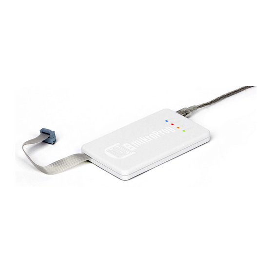
- Page 1 mikroProg for PIC® ™ mikroProg™ is a fast USB programmer with mikroICD™ hardware In-Circuit Debugger support. Smart engineering allows mikroProg to support PIC10, PIC12, PIC16, PIC18, dsPIC30/33, PIC24 and PIC32 devices in a single programmer!
- Page 2 TO OUR VALUED CUSTOMERS I want to express my thanks to you for being interested in our products and for having confidence in MikroElektronika. The primary aim of our company is to design and produce high quality electronic products and to constantly improve the performance thereof in order to better suit your needs.
-
Page 3: Table Of Contents
Table of Contents Introduction to mikroProg for PIC Connection examples - PIC dsPIC DIP18 Key features PIC DIP8 dsPIC TQFP44 1. Driver installation PIC DIP14 dsPIC DIP28 step 1 – Start installation PIC DIP18 dsPIC DIP40 step 2 – Accept EULA... -
Page 4: Introduction To Mikroprog For Pic
PIC represents fast reliable programmer with support. Specially designed firmware allows programming of all Microchip® microcontrollers: PIC, dsPIC and PIC32. And there’s no need for the firmware update each time you select a new microcontroller architecture. With mikroProg™, single firmware takes care of all supported architectures. Supporting new microcontrollers is easy. Just by downloading the latest version of mikroProg Suite™... -
Page 5: Key Features
In-Circuit Debugging (ICD). - Unique firmware for PIC, dsPIC PIC32 microcontrollers - No need for firmware update - New microcontrollers support via latest version of mikroProg Suite for PIC software - Power supply for target device Flat cable USB MINIB connector IDC10 connector DATA transfer indication LED ACTIVE indication LED... -
Page 6: Driver Installation
To install drivers for mikroProg for PIC go to download section on MikroElektronika website or follow link below. http://www.mikroe.com/eng/downloads/get/1202/ mikroprog_for_pic_drivers_v200.zip After download is complete extract files and begin installation: Folder with extracted files contains folders with drivers for different operating systems. Depending on which operating system is in use chose adequate folder and open it. -
Page 7: Step 1 - Start Installation
step 1 – Start installation step 2 – Accept EULA Next> In welcome screen click on button In order to proceed select: I accept the this EULA (End User License Agreement) Next> Click button Page 7... -
Page 8: Step 3 - Installing The Drivers
step 3 – Installing the drivers step 4 – Finish installation Drivers are installed automatically Click on Finish button to end installation process Page 8... -
Page 9: Connecting To A Pc
In order to use mikroProg for PIC connect it with a PC via USB cable, Figure 2-1. When connection is established green POWER LED will turn ON. Amber-colored LINK LED will turn ON when link between mikroProg and PC is established. Link can be established only when correct... -
Page 10: Mikroprog Suite For Pic Software
Program mikroProg Suite for PIC™ is intended for programming PIC®, dsPIC® and PIC32® microcontrollers from Microchip®. The graphic interface of this program is clear and easy-to-use, which makes the use of this program faster. The program’s main window includes basic options for programming microcontrollers. -
Page 11: Powering Device Via Mikroprog
One of key benefits on mikroProg is power supply mode which can be activated from mikroProg Suite for PIC software. Under mikroProg Suite for PIC window (MCU INFO button) you can set power supply voltage in range from 1.8V with output current up to 250mA. -
Page 12: Connecting With A Target Device
Figure 5-2: Knob and incision for easy orientation For connection with a target device mikroProg for PIC uses IDC10 connector, Figure 5-1. In order to make proper connection with the target board it is necessary to pay attention to IDC10 connector pinout. -
Page 13: Idc10 Pinout
MCU-VCC (colored wire) - MCU power supply MCU-PGC - Serial programming clock MCU-PGD - ICSP data MCU-MCLR - Master clear/Programming voltage - Ground These pins are used for multiplexing (see section 8.0 for more MCLR information) Figure 6-1: IDC10 pinout Page 13... -
Page 14: Connection Examples
When connecting mikroProg with your device via 1x5 header make sure to use front side of IDC10 connector (side with a knob and incision), Figure 7-2. For example, if you use some of Mikroelektronika’s products you may notice a clear markings for mikroProg IDC10 connector header, Figure 7-2. -
Page 15: Using 2X5 Male Headers
Instead of 1x5 male header you can use 2x5 male header. Main difference is that via 2x5 male connector you can use multiplexing feature of mikroProg for PIC (explained in section 8.0). Figure 7-4: Connecting mikroProg with Ready for PIC... -
Page 16: Multiplexer
While pins on MCU are separated from rest of the circuit they can not be used as I/O. By connecting mikroProg to the device programming is enabled and due to multiplexer when Multiplexer is specially designed circuit which serves as a switch. programming is finished programmable pins can be used as I/O Purpose of multiplexer is that there’s no need for disconnecting without mikroProg removal, Figure 8-2. -
Page 17: Multiplexer In Programming Mode
Multiplexer in programming mode mikroProg for PIC Multiplexer MCU-PGD PROG During programming, multiplexer disconnects MCU-PGC DATA MCLR microcontroller pins used for programming from the target MCLR device. This enables the programming process to be safely performed without affecting the operation of the device itself. It... -
Page 18: Connection Schematic Examples
Following examples demonstrate connections with some of the most popular supported MCUs. For all other MCUs consult manufacturer’s datasheet. All PIC, dsPIC and PIC32 MCUs use PGC, PGD and MCLR/Vpp pins for programming. Some MCUs have several groups of programming pins. For example dsPIC33FJ128GP710A has three pairs of programmable pins PGED1-PGEC1, PGED2-PGEC2 or PGED3-PGEC3 (MCLR/Vpp pin is same for all pin groups). -
Page 19: Connection Examples - Pic
100nF MCU-VCC PIC DIP8 MCU- GP1/PGC PGC- MCU- GP0/PGD PGD- USER INTERFACE MCU-GP3/MCLR MCLR Figure 9-1: Connection schematic for 8-pin DIP MCU via 2x5 male header On-board 8 PIN 2x5 male connector 100nF MCU-VCC PIC DIP14 MCU- RA1/ PGC- USER MCU- RA0/ PGD-... -
Page 20: Pic Dip18
100nF MCU-VCC MCU- RB6/ PGC- MCU- RB7/ PGD- USER PIC DIP18 MCU-MCLR INTERFACE MCLR OSC1 MCLR OSC2 On-board Figure 9-3: Connection schematic for 2x5 male connector 18-pin DIP MCU via 2x5 male header 18 PIN 100nF MCU-VCC MCU- RA1/ PGC- OSC1 MCU- RA0/... -
Page 21: Pic Dip28
PIC DIP28 PIC DIP40 Figure 9-6: Connection schematic for Figure 9-5: Connection schematic for 40-pin DIP MCU via 2x5 male header 28-pin DIP MCU via 2x5 male header 100nF 100nF MCU-VCC MCU-VCC MCLR MCLR PGC- MCU- RB6/ MCU- RB6/ PGC- MCU- RB7/ PGD-... -
Page 22: Pic Tqfp 64
PIC TQFP 64 Figure 9-7: Connection schematic for 64-pin TQFP MCU via 2x5 male header 100nF MCU-VCC PGC- MCU- RB6/ USER MCU- RB7/ PGD- INTERFACE MCU-MCLR MCLR On-board MCLR 2x5 male PIC18F6310 connector OSC2 OSC1 64 PIN Page 22... - Page 23 PIC TQFP 80 Figure 9-8: Connection schematic for 80-pin TQFP MCU via 2x5 male header 100nF MCU-VCC PGC- MCU- RB6/ USER MCU- RB7/ PGD- INTERFACE MCU-MCLR MCLR On-board 2x5 male connector MCLR PIC18F8310 OSC2 OSC1 80 PIN Page 23...
-
Page 24: Connection Examples - Pic18Fj
MCU-VCC 10uF 100nF MCLR MCU- RB6/PGC PGC- MCU- RB7/PGD PGD- USER INTERFACE MCU-MCLR MCLR PIC18FJ DIP28 On-board VCCcore 2x5 connector 10uF Figure 9-9: Connection OSC1 schematic for 28-pin DIP OSC2 MCU via 2x5 male header 28 PIN MCU-VCC 100nF PIC18FJ QFN28 10uF MCU- RB6/PGC... -
Page 25: Pic18Fj Dip40
PIC18FJ DIP40 Figure 9-11: Connection schematic for 40-pin DIP MCU via 2x5 male header MCU-VCC 10uF 100nF MCLR MCU- RB6/PGC PGC- USER PGD- MCU- RB7/PGD INTERFACE MCU-MCLR MCLR On-board VCCcore 2x5 connector 10uF OSC1 OSC2 DIP40 Page 25... -
Page 26: Pic18Fj Tqfp44
MCU-VCC 100nF 10uF MCU- RB6/PGC PGC- USER MCU- RB7/PGD PGD- INTERFACE MCU-MCLR PIC18FJ TQFP44 MCLR OSC2 OSC1 PIC18F44J10 On-board 2x5 connector Figure 9-12: Connection schematic for 44-pin TQFP MCU VCCcore via 2x5 male header 44 PIN 10uF MCU-VCC 100nF 10uF MCU- RB6/PGC PGC-... -
Page 27: Pic18Fj Tqfp64
PIC18FJ TQFP64 Figure 9-14: Connection schematic for 64-pin TQFP MCU via 2x5 male header 100nF MCU-VCC MCU- RB6/PGC PGC- USER MCU- RB7/PGD PGD- INTERFACE MCU-MCLR MCLR On-board MCLR 2x5 male connector PIC18F63J11 OSC2 OSC1 64 PIN Page 27... -
Page 28: Pic18Fj Tqfp80
PIC18FJ TQFP80 Figure 9-15: Connection schematic for 80-pin TQFP MCU via 2x5 male header MCU-VCC 10uF 100nF MCU- RB6/PGC PGC- USER MCU- RB7/PGC PGD- INTERFACE MCU-MCLR MCLR On-board 2x5 connector MCLR PIC18F83J11 VCCcore 10uF 80 PIN Page 28... -
Page 29: Pic18Fj Tqfp100
PIC18FJ TQFP100 Figure 9-16: Connection schematic for 100-pin TQFP MCU via 2x5 male header R 22K MCU-VCC 10uF 100nF MCU- RB6/PGC PGC- VCCRX TPIN+ USER MCU- RB7/PGD PGD- INTERFACE TPIN- MCU-MCLR MCLR GNDRX On-board 2x5 connector OSC2 PIC18F96J60 OSC1 MCLR VCCcore 10uF 100 PIN... -
Page 30: Connection Examples - Dspic
100nF MCU-VCC MCLR AVCC MCU- RB5/PGC PGC- dsPIC DIP18 AGND MCU- RB4/PGD PGD- USER INTERFACE MCU-MCLR MCLR On-board OSC1 Figure 9-17: Connection 2x5 connector OSC2 schematic for 18-pin DIP RC13 MCU via 2x5 male header RC14 18 PIN 100nF MCU-VCC MCU- RB6/PGC PGC-... -
Page 31: Dspic Dip28
dsPIC DIP28 dsPIC DIP40 Figure 9-20: Connection schematic for Figure 9-19: Connection schematic for 40-pin DIP MCU via 2x5 male header 28-pin DIP MCU via 2x5 male header 100nF 100nF MCU-VCC MCU-VCC MCLR AVCC MCLR AVCC MCU- RF2/PGC PGC- MCU- RB6/PGC PGC- AGND... -
Page 32: Dspic Tqfp64
dsPIC TQFP64 Figure 9-21: Connection schematic for 64-pin TQFP MCU via 2x5 male header 100nF MCU-VCC PGC- MCU- RB6/PGC USER MCU- RB7/PGD PGD- RC14 INTERFACE MCU-MCLR MCLR RC13 RD11 RD10 On-board MCLR 2x5 connector dsPIC30F5015 OSC2 OSC1 64 PIN Page 32... -
Page 33: Dspic Tqfp80
dsPIC TQFP80 Figure 9-22: Connection schematic for 80-pin TQFP MCU via 2x5 male header 100nF MCU-VCC PGC- MCU- RB6/PGC USER MCU- RB7/PGD PGD- RG15 RC14 INTERFACE MCU-MCLR MCLR RC13 RD11 RD10 On-board 2x5 connector RA15 MCLR RA14 dsPIC30F6014 OSC2 OSC1 RA12 RA13 80 PIN... -
Page 34: Pic24 Dip18
PIC24 DIP18 MCLR MCU-VCC RB15 MCU- RA1/PGC PGC- RB14 MCU- RA0/PGD PGD- USER Figure 9-23: Connection INTERFACE VCAP MCU-MCLR MCLR OSC1 schematic for 18-pin DIP OSC2 MCU via 2x5 male header On-board 2x5 connector PIC24 DIP20 MCLR MCU-VCC RB15 MCU- RA1/PGC PGC- RB14... -
Page 35: Pic24 Dip28
MCLR MCU-VCC RB15 PIC24 DIP28 MCU- RB1/PGC RB14 MCU- RB0/PGD RB13 MCU-MCLR RB12 RB11 Figure 9-25: Connection On-board RB10 2x5 connector schematic for 28-pin DIP VCAP MCU via 1x5 male header MCU-VCC MCU-VCC PIC24 TQFP44 PGC- MCU- RB6/PGC USER MCU- RB7/PGD PGD- INTERFACE... -
Page 36: Pic24 Tqfp64
PIC24 TQFP64 Figure 9-27: Connection schematic for 64-pin TQFP MCU via 2x5 male header MCU-VCC MCU- RB6/PGC PGC- RC14 USER MCU- RB7/PGD PGD- RC13 INTERFACE MCU-MCLR MCLR RD11 RD10 On-board MCLR 2x5 connector PIC24FJ128GA006-PT OSC2 OSC1 64 PIN Page 36... -
Page 37: Pic24 Tqfp80
PIC24 TQFP80 Figure 9-28: Connection schematic for 80-pin TQFP MCU via 2x5 male header MCU-VCC RC14 PGC- MCU- RB6/PGC RC13 USER MCU- RB7/PGD PGD- INTERFACE MCU-MCLR MCLR RD11 RD10 On-board RA15 2x5 connector MCLR RA14 PIC24FJ128GB108-PT OSC2 OSC1 D+/RG2 D-/RG3 VUSB VBUS 80 PIN... -
Page 38: Pic24 Tqfp100
PIC24 TQFP100 Figure 9-29: Connection schematic for 100-pin TQFP MCU via 2x5 male header MCU-VCC RG15 PGC- MCU- RB6/PGC RC14 USER MCU- RB7/PGD PGD- INTERFACE RC13 MCU-MCLR MCLR RD11 RD10 On-board 2x5 connector RA15 RA14 OSC2 OSC1 MCLR PIC24FJ128GB110-PF USBDP/D+/RG2 USBDN/D-/RG3 VUSB USB-DET/VBUS... -
Page 39: Pic24 Tqfp100
PIC24 TQFP100 Figure 9-30: Connection schematic for 100-pin TQFP MCU via 1x5 male header MCU-VCC RG15 MCU- RB6/PGC RC14 MCU- RB7/PGD RC13 MCU-MCLR RD11 RD10 On-board 2x5 connector RA15 RA14 OSC2 OSC1 MCLR PIC24FJ128GB110-PF USBDP/D+/RG2 USBDN/D-/RG3 VUSB USB-DET/VBUS 100 PIN Page 39... -
Page 40: Pic32 Tqfp64
PIC32 TQFP64 Figure 9-31: Connection schematic for 64-pin TQFP MCU via 2x5 male header MCU-VCC MCU- RB6/PGC PGC- USER MCU- RB7/PGD PGD- INTERFACE MCU-MCLR MCLR SOSCO SOSCI On-board RD11 2x5 connector RD10 MCLR OSC2 PIC32MX534F064H OSC1 D+/RG2 D-/RG3 VUSB VBUS USB-ID Page 40... -
Page 41: Pic32 Tqfp100
PIC32 TQFP100 Figure 9-32: Connection schematic for 100-pin TQFP MCU via 2x5 male header VCC3 10uF RG15 MCU-VCC VCC3 RC14 RC13 MCU- RB6/PGC PGC- USER MCU- RB7/PGD PGD- RD11 INTERFACE MCU-MCLR MCLR RD10 RA15 On-board RA14 2x5 connector OSC2 PIC32MX795F512L MCLR OSC1 VCC3... - Page 42 Notes: Page 42...
- Page 43 No part of this manual, including product and software described herein, may be reproduced, stored in a retrieval system, translated or transmitted in any form or by any means, without the prior written permission of MikroElektronika. The manual PDF edition can be printed for private or local use, but not for distribution.
- Page 44 PIC® If you want to learn more about our products, please visit our website at www.mikroe.com If you are experiencing some problems with any of our products or just need additional information, please place your ticket at www.mikroe.com/en/support...
Need help?
Do you have a question about the mikroProg for PIC and is the answer not in the manual?
Questions and answers