Table of Contents
Advertisement
Quick Links
mikroMMB for dsPIC33
™
User manual
All MikroElektronika´s development systems represent irreplaceable
tools for programming and developing microcontroller-based devices.
Carefully chosen components and the use of machines of the last
generation for mounting and testing thereof are the best guarantee of
high reliability of our devices. Due to simple design, a large number of
add-on modules and ready to use examples, all our users, regardless
of their experience, have the possibility to develop their project in a fast
and efficient way.
Advertisement
Table of Contents

Related Manuals for mikroElektronika mikroMMB for dsPIC33


Summary of Contents for mikroElektronika mikroMMB for dsPIC33
- Page 1 ™ User manual All MikroElektronika´s development systems represent irreplaceable tools for programming and developing microcontroller-based devices. Carefully chosen components and the use of machines of the last generation for mounting and testing thereof are the best guarantee of high reliability of our devices.
- Page 2 TO OUR VALUED CUSTOMERS I want to express my thanks to you for being interested in our products and for having confidence in Mikroelektronika. The primary aim of our company is to design and produce high quality electronic products and to constantly improve the performance thereof in order to better suit your needs.
-
Page 3: Table Of Contents
TABLE OF CONTENTS General information .......................... 4 Key features ............................. 5 1.0. Development system connection ....................6 2.0. dsPIC33FJ128GP710 microcontroller ..................7 3.0. dsPIC33FJ128GP710 microcontroller programming ..............8 4.0. Touch Screen ..........................10 5.0. Flash Memory Module ......................11 6.0. -
Page 4: General Information
General information The mikroMMB for dsPIC33 is a compact development system which provides a convenient platform for development of devices with multimedia contents. The central part of the system is a 16-bit microcontroller dsPIC33FJ128GP710 that is programmed with the LV24-33 external programmer from Mikroelektronika or with ICD2 ®... -
Page 5: Key Features
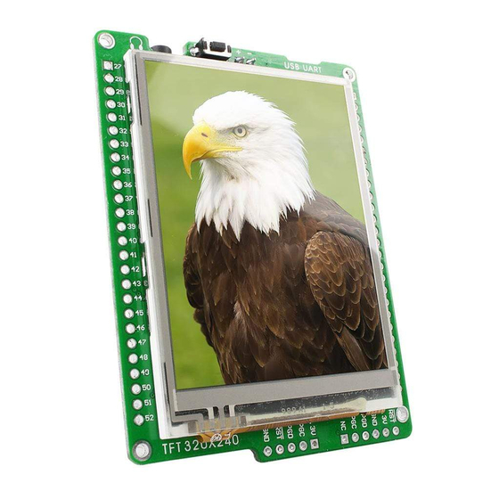
Key features 1. Pads 5. Pads 2. TFT 320x240 display 6. Headphone connector 3. Pads used to connect ICD2 and ICD3 programmers 7. USB MINI-B connector 4. Pads used to connect the LV24-33 programmer MikroElektronika... -
Page 6: Development System Connection
1.0. Development system connection Connect the development system to a PC via a USB cable, Figure 1-1. The TFT display will be automatically turned on. Figure 1-1: Powering the development system Figure 1-2: USB connector and microcontroller connection schematic The USB connector is used to access the UART2 module built into the microcontroller. -
Page 7: Dspic33Fj128Gp710 Microcontroller
2.0. dsPIC33FJ128GP710 microcontroller The mikroMMB for PIC33 development system comes with the dsPIC33FJ128GP710 microcontroller. This high-performance 16-bit microcontroller with its integrated modules and in combination with other on-board modules is ideal for multimedia applications. Key features of the microcontroller: - Up to 40 MIPS Operation;... -
Page 8: Dspic33Fj128Gp710 Microcontroller Programming
3.0. dsPIC33FJ128GP710 microcontroller programming The microcontroller is programmed with LV24-33, ICD2 ® or ICD3 ® programmer. The LV24-33 programmer is connected to the development system via the CN1 connector, Figure 3-2. The CN9 connector is used to connect ICD2 and ICD3 programmers, Figure 3-4. - Page 9 Figure 3-4: Connecting ICD2 connector Figure 3-5: Connecting ICD2 or ICD3 programmer In order to enable the ICD2 and ICD3 programmers to be connected to the development system, it is necessary to provide the appropriate connector such as the ICD2 CONNECTOR BOARD. This connector should be first soldered on the CN9 connector, Figure 3-4.
-
Page 10: Touch Screen
4.0. Touch screen The development system features a TFT 320x240 display covered with a sensitive touch panel. Together they form a functional unit called a touch screen. It enables data to be entered and displayed at the same time. The way of entering and displaying data depends on the program loaded into the microcontroller. -
Page 11: Flash Memory Module
5.0. Flash memory module Since multimedia applications are getting increasingly demanding, it is necessary to provide additional memory space to be used for storing programs by the microcontroller. The flash memory module enables the microcontroller to use additional 8Mbit flash memory. -
Page 12: Mmc/Sd Connector
6.0. MMC/SD connector There is a built-in MMC/SD connector for MMC/SD cards provided on the development system. It enables the system to additionally expand available memory space. The Serial Peripheral Interface (SPI) is used for communication between the microcontroller and MMC/SD card. -
Page 13: Audio Module
7.0. Audio module The mikroMMB for PIC33 features an audio module providing an interface for stereo headphones.This module enables audio reproduction by using stereo headphones connected to the system via a 3.5mm connector CN6. Volume as well as other functions of this module are controlled by the microcontroller from within the software using the Serial Peripheral Interface (SPI). -
Page 14: Pads
8.0. Pads The access to the microcontroller pins on the development system is enabled via pads provided along the two long sides of the development system. Figure 8-1: Pads Figure 8-2: Pads and microcontroller connection schematic MikroElektronika... - Page 15 MikroElektronika has been advised of the possibility of such damages. MikroElektronika reserves the right to change information contained in this manual at any time without prior notice, if necessary.
Need help?
Do you have a question about the mikroMMB for dsPIC33 and is the answer not in the manual?
Questions and answers