
Related Manuals for mikroElektronika mikromedia for PIC32


Summary of Contents for mikroElektronika mikromedia for PIC32
- Page 1 mikromedia ™ for PIC32 ® Compact development system rich with on-board peripherals for all-round multimedia development on PIC32MX460F512L device. PIC32...
- Page 2 TO OUR VALUED CUSTOMERS I want to express my thanks to you for being interested in our products and for having confidence in Mikroelektronika. The primary aim of our company is to design and produce high quality electronic products and to constantly improve the performance thereof in order to better suit your needs.
-
Page 3: Table Of Contents
Table of Contents Introduction to mikromedia for PIC32 Programming with mikroProg programmer ® ™ Package Contains mikroProg Suite for PIC Software ™ ® Key Features Programming with ICD2 or ICD3 programmer ® ® System Specification 4. Reset Button 1. Power supply 5. -
Page 4: Introduction To Mikromedia For Pic32
Introduction to mikromedia for PIC32 ® mikromedia for PIC32 is a compact ® development system with lots of on-board peripherals which allow development of devices with multimedia contents. The central part of the system is a 32-bit PIC32MX460F512L microcontroller. The mikromedia for PIC32 ®... -
Page 5: Package Contains
PRODUCT DVD www.mikroe.com www.libstock.com Copyright ©2012 Mikroelektronika. All rights reserved. MikroElektronika, MikroElektronika logo and other MikroElektronika trademarks are the property of MikroElektronika. All other trademarks are the property of their respective owners. Unauthorized copying, hiring, renting, public performance and broadcasting of this DVD is strictly prohibited. -
Page 6: Key Features
Key Features Connection Pads TFT 320x240 display USB MINI-B connector CHARGE indication LED LI-Polymer battery connector 3.5mm headphone connector Power supply regulator Serial Flash memory RESET button VS1053 Stereo mp3 coder/decoder PIC32MX460F512L microcontroller Accelerometer Crystal oscillator Power indication LED microSD Card Slot ICD2/3 connector mikroProg connector Page 6... -
Page 7: System Specification
System Specification power supply Via USB cable (5V DC) power consumption 58 mA with erased MCU (when on-board modules are inactive) board dimensions 81.2 x 60.5mm (3.19 x 2.38 inch) weight ~50 g (0.11 lbs) Page 7... -
Page 8: Power Supply
1. Power supply USB power supply You can apply power supply to the board using MINI-B USB cable provided with the board. On-board voltage regulators provide the appropriate voltage levels to each component on the board. Power LED (GREEN) will indicate the presence of power supply. - Page 9 VCC-SYS VCC-USB VCC-SYS PMEG3010ER HDR1 HDR2 DMP2160UW FERRITE VBUS VCC-BAT USB MINIB 10nF BATT CONN VCC-3.3 VCC-1.8 VCC-BAT VCC-1.8 VREF-1.8 VCC-1.8 10uF 2.2uF Vout VSENSE 220K FERRITE 10uF MIC5205-ADJ 100K VCC-3.3 VCC-3.3 VCC-3.3 M1X26 M1X26 VCC-3.3 VCC-3.3 VCC-3.3 VCC-BAT VCC-SYS CHARGE VCC-SYS VCC-3.3...
-
Page 10: Pic32Mx460F512L Microcontroller
2. PIC32MX460F512L microcontroller mikromedia for PIC32 development system comes with the ® PIC32MX460F512L microcontroller. This high-performance 32-bit microcontroller with its integrated modules and in combination with other on-board modules is ideal for multimedia applications. Key microcontroller features - 1.56 DMIPS/MHz, 32-bit MIPS M4K Core;... -
Page 11: Programming The Microcontroller
3. Programming the microcontroller Figure 3-1: PIC32MX460F512L microcontroller The microcontroller can be programmed in three ways: Over USB HID mikroBootloader Using mikroProg external programmer ™ Using ICD2/3 external programmer Page 11... -
Page 12: Programming With Mikrobootloader
Programming with mikroBootloader step 1 – Connecting mikromedia You can program the microcontroller with bootloader which is pre-programmed by default. To transfer .hex file from a PC to (mikroBootloader USB MCU you need bootloader software HID) which can be downloaded from: http://www.mikroe.com/downloads/get/1605/ mikrobootloader_pic32_v200.zip After the mikroBootloader software is downloaded, unzip it to... -
Page 13: Step 2 - Browsing For .Hex File
step 2 – Browsing for .HEX file step 3 – Selecting .HEX file Figure 3-3: Browse for HEX Figure 3-4: Selecting HEX Click the Browse for HEX button and from a Select .HEX file using open dialog window. pop-up window (Figure 3.4) choose the .HEX file Open Click the button. -
Page 14: Step 4 - Uploading .Hex File
step 4 – Uploading .HEX file Figure 3-5: Begin uploading Figure 3-6: Progress bar To start .HEX file bootloading click the Progress bar enables you to monitor .HEX file upload- Begin uploading button. ing. Page 14... -
Page 15: Step 5 - Finish Upload
step 5 – Finish upload Figure 3-7: Restarting MCU Figure 3-8: mikroBootloader ready for next job Click button after the uploading process is finished Reset Press button on mikromedia board and wait for 5 seconds. Your program will run automatically Page 15... -
Page 16: Programming With Mikroprog Programmer
Programming with mikroProg ™ programmer mikroProg The microcontroller can be programmed with ™ programmer mikroProg Suite for PIC software. The ™ ® mikroProg programmer is connected to the development ™ system via the CN6 connector, Figure 3-9. mikroProg is a fast ™... -
Page 17: Mikroprog Suite ™ For Pic ® Software
mikroProg Suite for PIC Software ™ ® PIC32 mikroProg programmer requires ™ special programming software called mikroProg Suite for PIC . This ™ ® software is used for programming of ALL Microchip microcontroller families, ® including PIC10 , PIC12 , PIC16 , PIC18 ®... -
Page 18: Programming With Icd2
Programming with ICD2 or ICD3 programmer ® ® The microcontroller can be also programmed with ICD2 ® or ICD3 programmer. These programmers connects ® ICD2 CONNECTOR BOARD. with mikromedia board via Figure 3-12: Connecting ICD2 ® or ICD3 programmer ® In order to enable the ICD2 and ICD3 programmers to be connected to the... - Page 19 Vcap 10uF VCC-3.3 VCC-3.3 VCC-3.3 VCC-3.3 100nF 100nF 100nF RG15 VCC-3.3 VCC-3.3 VCC-3.3 RC14 RC13 RD11 10uF 100nF 100nF RD10 RA15 RG6/SCK2 RA14 RG7/SDI2 PIC32MX460F512L RG8/SDO2 OSC2 MCLR# MCLR OSC1 VCC-3.3 MCLR# RA0/TMS SDA2/RA3 RE8/INT1 SCL2/RA2 PGD2 RE9/INT2 D+/RG2 PGC2 D-/RG3 VUSB VBUS...
-
Page 20: Reset Button
4. Reset Button Board is equipped with reset button, which is located at the top of the front side (Figure 4-2). If you want to reset the circuit, press the reset button. It will generate low voltage level on microcontroller reset pin (input). In addition, a reset can be externally provided through pin 27 on side headers (Figure 4-3). - Page 21 Vcap 10uF VCC-3.3 VCC-3.3 C31 22pF 100nF RG15 SOSCO RC14 SOSCI C30 22pF RC13 RD11 HDR2 RD10 22pF RA15 RG6/SCK2 RA14 RG7/SDI2 CLKO PIC32MX460F512L RG8/SDO2 OSC2 CLKI 22pF MCLR OSC1 VCC-3.3 VCC-3.3 VCC-3.3 VCC-3.3 VCC-3.3 VCC-3.3 RA0/TMS SDA2/RA3 RE8/INT1 SCL2/RA2 RE9/INT2 D+/RG2 D-/RG3...
-
Page 22: Crystal Oscillator
5. Crystal oscillator 8MHz crystal oscillator Board is equipped with (X1) circuit that provides external clock waveform to the microcontroller CLKO and CLKI pins. This base frequency is suitable for further clock multipliers and ideal for generation of necessary USB clock, which ensures proper operation of bootloader and your custom USB-based 32.768kHz Crystal oscillator applications. -
Page 23: Microsd Card Slot
6. microSD Card Slot microSD card slot Board contains for using microSD cards in your projects. It enables you to store large amounts of data externally, thus saving microcontroller memory. microSD cards use Serial Peripheral Interface (SPI) for communication with the microcontroller. -
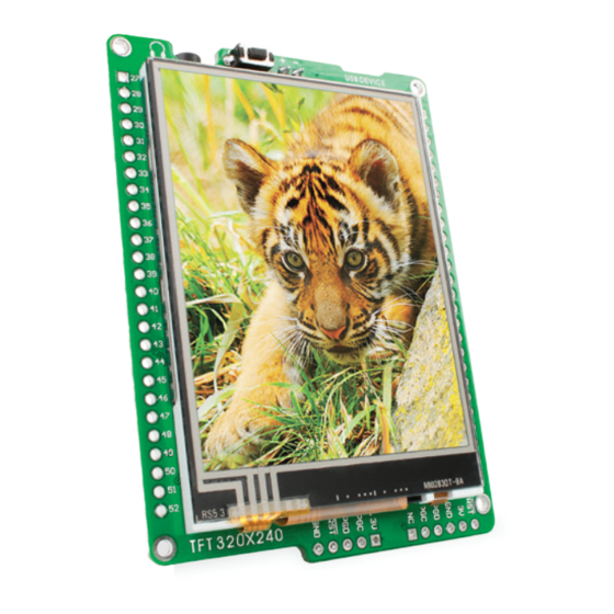
Page 24: Touch Screen
7. Touch Screen The development system features a TFT 320x240 display covered with a resistive touch screen. touch panel. Together they form a functional unit called a It enables data to be entered and displayed at the same time. The TFT display is capable of showing graphics in 262.144 diffe rent colors. - Page 25 Vcap 10uF VCC-SYS VCC-3.3 TFT1 VCC-3.3 LED-K LED-A1 BC846 LED-A2 VCC-SYS LED-A3 LED-A4 LCD-BLED RG15 BAT43 RC14 BC846 PMD5 LCD-RST RESET RC13 PMD6 VSYNC PMD7 RD11 HSYNC LCD-RST RD10 DOTCLK BC846 ENABLE PMD15 VCC-3.3 DB17 PMD14 RA15 DB16 VCC-3.3 VCC-3.3 VCC-3.3 PMD13 DB15...
-
Page 26: Audio Module
8. Audio Module Figure 8-1: On-board VS1053 MP3 codec Figure 8-2: features stereo audio codec VS1053. This module The mikromedia for PIC32 ® Inserting 3.5mm enables audio reproduction by using stereo headphones connected to the headphones jack system via a 3.5mm... - Page 27 Vcap 10uF VCC-3.3 VCC-3.3 VCC-1.8 VCC-3.3 MP3-CS# RG15 10uF MP3-CS# RC14 100K 3.3nF RC13 MP3-RST# RD11 RD10 MP3-RST# MP3-DREQ 10uF 100K RA15 3.3nF SCK2-RG6 RG6/SCK2 RA14 MISO2-RG7 MP3-BSYNC RG7/SDI2 XDCS/BSYNC MOSI2-RG8 PIC32MX460F512L RG8/SDO2 OSC2 IOVDD1 AGND3 LEFT LEFT MCLR OSC1 LEFT DGND1 AVDD2...
-
Page 28: Usb Connection
9. USB connection PIC32MX460F512L microcontroller has integrated USB module, which enables you to implement USB communication functionality to your mikromedia board. Connection with target USB host is done over MINI-B USB connector which is positioned next to the battery connector. Figure 9-1: Connecting USB cable to MINI-B USB connector... - Page 29 Vcap 10uF VCC-3.3 VCC-3.3 VCC-3.3 VCC-3.3 100nF 100nF 100nF C31 22pF RG15 SOSCO RC14 VCC-3.3 VCC-3.3 VCC-3.3 SOSCI C30 22pF RC13 RD11 RD10 10uF 100nF 100nF 22pF RA15 RG6/SCK2 RA14 RG7/SDI2 CLKO RG8/SDO2 PIC32MX460F512L OSC2 CLKI 22pF MCLR OSC1 USB-ID-RF3 USB-ID RA0/TMS SDA2/RA3...
-
Page 30: Accelerometer
10. Accelerometer ADXL345 On board accelerometer is used to measure acceleration in three axis: x, y and z. The accelerometer function is defined by the user in the program loaded into the microcontroller. Communication between the accelerometer and the microcontroller is performed I 2 C via the interface. -
Page 31: Flash Memory
11. Flash Memory Vcap 10uF VCC-3.3 RG15 VCC-3.3 VCC-3.3 VCC-3.3 RC14 RC13 RD11 100nF 100nF 100nF RD10 Figure 11-1: FLASH-CS# R5 27 Flash memory module RA15 SCK2-RG6 RG6/SCK2 RA14 VCC-3.3 VCC-3.3 VCC-3.3 MISO2-RG7 RG7/SDI2 MOSI2-RG8 PIC32MX460F512L RG8/SDO2 OSC2 R4 27 MCLR OSC1 10uF... -
Page 32: Pads
12. Pads Vcap 10uF VCC-3.3 VCC-SYS HDR1 HDR2 RG15 RC14 RC13 RD11 RD11 RD10 RD10 RA15 RA15 SCK2-RG6 RA14 RB14 RG6/SCK2 RA14 MISO2-RG7 RG7/SDI2 MOSI2-RG8 PIC32MX460F512L RG8/SDO2 OSC2 RA14 MCLR OSC1 RA15 RA10 RD10 RD11 SDA2-RA3 RA0/TMS SDA2/RA3 RD14 SCL2-RA2 RE8/INT1 SCL2/RA2 RD15... -
Page 33: Pinout
13. Pinout 5V power supply VSYS Reset pin Reference Ground left ch. audio out right ch. Analog Lines PWM lines RB14 Interrupt Lines RA14 RA15 RA10 Digital I/O lines RD10 RD11 RD14 Digital I/O lines RD15 RG12 RG13 RG14 UART SCK2 SDI2 SCL2... -
Page 34: Dimensions
14. Dimensions 81.15 mm (3195 mils) 73.66 mm (2900 mils) 63.5 mm (2500 mils) 2.54 mm 2.67 mm (100 mils) (105 mils) Page 34... -
Page 35: Mikromedia Accessories
15. mikromedia accessories We have prepared a set of extension boards pin-compatible with your mikromedia, which enable you to easily expand your board basic functionality. call them mikromedia shields. But we also offer other accessories, such as Li-polymer battery, stacking headers, wire jumpers and more. -
Page 36: What's Next
What’s next? You have now completed the journey through each and every feature of mikromedia for PIC32 board. You got to know it’s modules and ® organization. Now you are ready to start using your new board. We are suggesting several steps which are probably the best way to begin. - Page 37 Notes: Page 37...
- Page 38 Notes: Page 38...
- Page 39 No part of this manual, including product and software described herein, may be reproduced, stored in a retrieval system, translated or transmitted in any form or by any means, without the prior written permission of MikroElektronika. The manual PDF edition can be printed for private or local use, but not for distribution.
- Page 40 If you are experiencing some problems with any of our products or just need additional information, please place your ticket at www.mikroe.com/esupport If you have any questions, comments or business proposals, mikromedia for PIC32 Manual ver. 1.10c do not hesitate to contact us at office@mikroe.com...
Need help?
Do you have a question about the mikromedia for PIC32 and is the answer not in the manual?
Questions and answers