Advertisement
Quick Links
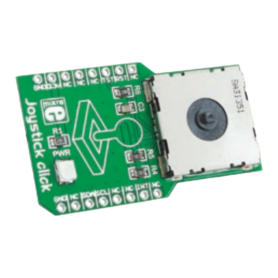
Joystick
click
1. Introduction
Joystick click
is an accessory board in
™
mikroBUS
form factor. It's a compact and
™
easy solution for adding joystick to your
design. It features
AS5013
Hall IC as well
as
N50P105
miniature magnetic joystick
module.
Joystick
click
™
communicates
with the target board microcontroller via
mikroBUS
I
C (SDA, SCL), INT, RST and CS
™
2
lines. The board is designed to use 3.3V
power supply only. LED diode (GREEN)
indicates the presence of power supply.
2. Soldering the headers
Before using your click
board, make sure
™
to solder 1x8 male headers to both left
and right side of the board. Two 1x8 male
headers are included with the board in
the package.
2
Turn the board upside down so that
bottom side is facing you upwards.
Place shorter pins of the header into the
appropriate soldering pads.
1
3
Turn the board upward again. Make sure
to align the headers so that they are
perpendicular to the board, then solder the
pins carefully.
3. Plugging the board in
Once you have soldered the headers your
board is ready to be placed into desired
mikroBUS
™
socket. Make sure to align the
cut in the lower-right part of the board
with the markings on the silkscreen at
the mikroBUS
socket. If all of the pins are
™
aligned correctly, push the board all
the way into the socket.
4. Essential features
Joystick click
with its
AS5013
IC and
™
N50P105
represents smart navigation
key concept based on contactless, magnetic
movement detection. The
AS5013
includes
five integrated Hall sensing elements which
are monitoring the movement of the magnet,
incorporated into the joystick, and provides
directly the x and y coordinates via I
C output.
2
An integrated mechanical push button is also
built in joystick.
click
BOARD
www.mikroe.com
Joystick click Manual
ver. 1.00
0 100000 025062
Advertisement

Subscribe to Our Youtube Channel
Related Manuals for mikroElektronika Joystick click


Summary of Contents for mikroElektronika Joystick click
- Page 1 C (SDA, SCL), INT, RST and CS with the markings on the silkscreen at ™ Joystick click Manual lines. The board is designed to use 3.3V the mikroBUS socket. If all of the pins are ™...
- Page 2 MikroElektronika assumes no responsibility or liability for any errors or inaccuracies that may appear in the present document. Specification and information contained in the present schematic are subject to change at any time without notice. Copyright © 2013 MikroElektronika. All rights reserved.
Need help?
Do you have a question about the Joystick click and is the answer not in the manual?
Questions and answers