Advertisement
Quick Links
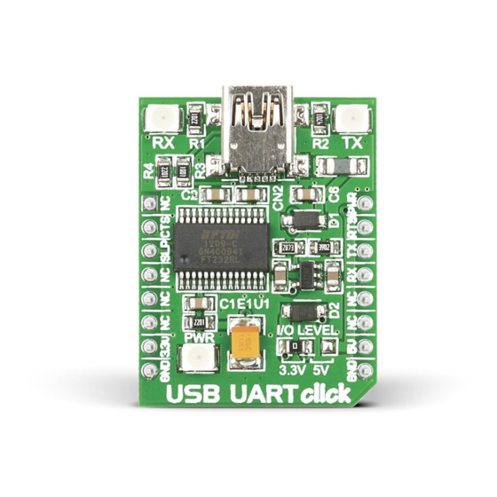
USB UART
click
1. Introduction
USB UART Click
is an accessory board in
™
mikroBUS™
form factor. It's a compact
and easy solution for adding serial UART
communication via USB cable. It features
FT232RL
USB-to-UART interface module
as well as USB MINI B connector. USB UART
Click
communicates with target board via
™
UART interface. The board is designed to
use 3.3V or 5V I/O level. It has a LED diode
(GREEN) that indicates the presence of
power supply.
2. Soldering the headers
Before using your click board
, make sure
™
to solder 1x8 male headers to both left
and right side of the board. Two 1x8 male
headers are included with the board in
the package.
2
Turn the board upside down so that
bottom side is facing you upwards. Place
shorter parts of the header pins in both
soldering pad locations.
1
3
Turn the board upward again. Make sure
to align the headers so that they are
perpendicular to the board, then solder the
pins carefully.
3. Plugging the board in
Once you have soldered the headers your
board is ready to be placed into desired
mikroBUS
™
socket. Make sure to align the
cut in the lower-right part of the board
with the markings on the silkscreen at
the mikroBUS
socket. If all of the pins are
™
aligned correctly, push the board all
the way into the socket.
4. Essential features
USB UART Click
with it's
FT232RL
™
gives additional serial UART communication
via USB cable. The
FT232RL
contains
integrated 1024 bit EEPROM, 128 bytes
long receive buffer, 256 bytes long transmit
buffer, configurable CBUS I/0 pins and entire
USB protocol handled on the chip. The board
contains RX and TX LED diodes that indicate
the transmit and receive data via USB.
click
BOARD
www.mikroe.com
USB UART click Manual
ver. 1.01
0 100000 021231
IC
Advertisement

Subscribe to Our Youtube Channel
Related Manuals for mikroElektronika USB UART click


Summary of Contents for mikroElektronika USB UART click
- Page 1 Click communicates with target board via with the markings on the silkscreen at ™ USB UART click Manual UART interface. The board is designed to the mikroBUS socket. If all of the pins are ™...
- Page 2 MikroElektronika assumes no responsibility or liability for any errors or inaccuracies that may appear in the present document. Specification and information contained in the present schematic are subject to change at any time without notice. Copyright © 2012 MikroElektronika. All rights reserved.
Need help?
Do you have a question about the USB UART click and is the answer not in the manual?
Questions and answers