Table of Contents
Advertisement
Quick Links
Advertisement
Table of Contents

Related Manuals for mikroElektronika EasyPIC v7


Summary of Contents for mikroElektronika EasyPIC v7
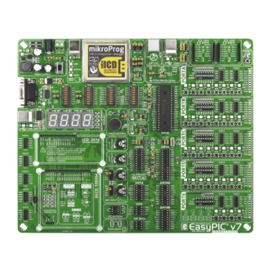
- Page 1 EasyPIC for dsPIC30 ® 14 microcontrollers supported Supports 3.3V and 5V devices Easily add extra boards Four connectors for each port Fast USB 2.0 programmer and dsPIC30 in DIP package Dual Power Supply mikroBUS sockets Amazing Connectivity In-Circuit Debugger ® ™...
- Page 2 To our valued customers From the day one, we in MikroElektronika gave ourselves the highest possible goals in pursuit of excellence. That same day, the idea of EasyPIC development board was born. In its each and tiniest piece we had put ™...
-
Page 3: Table Of Contents
Introduction Connectivity mikroBUS sockets ....... . ™ Introduction ........Input/Output Group . -
Page 4: Introduction
Introduction dsPIC30F microcontrollers are 16-bit high-performance digital signal ® controllers suitable for advanced motor control algorithms, digital power converters, speech and audio applications. We realized that benefit and start to develop a new system which is convenient for wide range of dsPIC30F microcontroller family produced in DIP packages. -
Page 5: It's Good To Know
It's good to know dsPIC30F4013 is the default microcontroller! System Specification dsPIC30F4013 is the default chip of EasyPIC ™ - Great choice for both beginners power supply for dsPIC30 . It has 30 MIPS operation, 48K bytes ® and professionals 7–23V AC or 9–32V DC of program memory, 2048 bytes... -
Page 6: Dual Power Supply
Dual power supply Board contains switching power supply that creates stable voltage and current levels necessary for powering each part of the board. Power supply section contains two power regulators: MC34063A, which generates VCC- 5V, and MC33269DT3.3 which creates VCC-3.3V power supply. - Page 7 EasyPIC v7 for dsPIC30 development board Power supply: via DC connector or screw terminals ™ ® supports both 3.3V and 5V power supply on a (7V to 23V AC or 9V to 32V DC), single board. This feature enables you to use or via USB cable (5V DC) wide range of peripheral boards.
-
Page 8: Supported Microcontrollers
Supported VCC-MCU VCC-MCU VCC-MCU VCC-MCU VCC-MCU VCC-MCU VCC-MCU VCC-MCU VCC-MCU VCC-MCU 10uF 100nF 100nF 100nF 100nF 10uF 100nF 100nF 100nF 100nF microcontrollers DIP40A DIP40B VCC-MCU VCC-MCU VCC-MCU VCC-MCU MCU-VPP MCU-VPP RB10 RB11 RB12 RB6-PGC RB7-PGD OSC1A OSC1A OSC1B OSC1B RC13 RF2-PGC RC13 Board contains six DIP sockets: DIP40A, DIP40B, DIP28A, DIP28B, DIP28C, DIP18. - Page 9 How to properly place your microcontroller into the DIP socket? Figure 4-3: Place both ends of microcontroller on Figure 4-4: with both fingers, evenly distribute Figure 4-5: Properly placed microcontroller will the socket so the pins are aligned correctly the force and press the chip into the socket. have equally leveled pins.
-
Page 10: On-Board Programmer
On-board programmer Socket selection Jumpers J1, J2, J3 and J4 are used to select PGC and PGD programming lines for your microcontroller. Make sure to place jumpers in the proper position for your socket. DIP40A DIP40B DIP28C DIP18 DIP28A DIP28B Why so many LEDs? Three LEDs indicate specific programmer operation. - Page 11 LINK ACTIVE DATA VCC-MCU VCC-BRD VCC-3.3V VCC-5V VCC-3.3V VCC-3.3V VCC-5V VCC-USB LD43 LD44 LD45 VCC-USB LED-DATA LED-DATA LED-ACT USB-PROG_N LED-ACT USB-PROG_N LED-USB LED-USB USB-PROG_P USB-PROG_P VCC-BRD 100nF MCLR# BRD-PGD BRD-PGD MCU-VPP BRD-PGC MCU-VPP BRD-PGC MCU-PGC MCLR# MCU-PGC MCLR# 100nF MCU-PGD MCU-PGD RF2-PGC RF3-PGD...
-
Page 12: Installing Programmer Drivers
Installing programmer drivers On-board mikroProg requires drivers in order to work. ™ Drivers are located on the that you received with the EasyPIC v7 for dsPIC30 package: ™ ® http://www.mikroe.com/downloads/get/1202/ mikroprog_for_pic_drivers_v200.zip When you locate the drivers, please extract files from the ZIP archive. -
Page 13: Programming Software
Programming software mikroProg Suite for PIC ™ ® Installation wizard - 6 simple steps On-board mikroProg ™ programmer requires special programming software called mikroProg Suite for PIC ™ ® . This software is used for programming all of Microchip ® microcontroller families, including PIC10, PIC12, PIC16, PIC18, dsPIC30/33, PIC24 and PIC32. -
Page 14: Mikroicd ™ - In Circuit Debugger
™ tools on the market. Supported Compilers All MikroElektronika compilers, mikroC , mikroBasic ™ ™ mikroPascal for PIC , dsPIC... - Page 15 ™ Here is a short overview of which debugging commands are supported in MikroElektronika compilers. You can see what each command does, and what are their shortcuts when you are in debugging mode. It will give you some general picture of what your debugger can do.
-
Page 16: Uart Via Rs-232
UART via RS-232 UART (universal asynchronous receiver/transmitter) is one of the most Enabling RS-232 common ways of exchanging data between the MCU and peripheral components. It is a serial protocol with separate transmit and receive lines, and can be used for full-duplex communication. -
Page 17: Uart Via Usb
UART via USB Modern PC computers, laptops and notebooks are no longer equipped with RS-232 connectors Enabling USB-UART and UART controllers. They are nowadays replaced with USB connectors and USB controllers. Still, certain technology enables UART communication to be done over USB connection. -
Page 18: Can Communication
CAN communication Controller Area Network (CAN or CAN bus) is a vehicle bus standard designed to allow microcontrollers and devices to communicate with each other within a vehicle without a host computer. CAN is a message-based protocol, designed specifically for automotive applications but now also used in other Enabling CAN areas such as industrial automation and medical equipment. -
Page 19: Mikrobus ™ Sockets
Success of the USB standard comes from it’s simplicity of usage and high and reliable data mikroBUS host connector ™ transfer rates. As we in MikroElektronika see it, mikroBUS pinout explained ™ Plug-and-Play devices with minimum settings are the future in embedded world too. This is... - Page 20 ™ ™ Click Boards are plug-n-play! ™ MikroElektronika portfolio of over 200 accessory boards is now enriched literally zero hardware configuration. Just plug and play. Visit the Click boards ™ by an additional set of mikroBUS compatible Click Boards . Almost each webpage for the complete list of available boards: ™...
- Page 21 WiFi PLUS click GPS click RS485 click CAN SPI click THERMO click ™ ™ ™ ™ ™ Code Examples It easy to get your Click board ™ up and running. We provided the examples for mikroC ™ mikroBasic and mikroPascal ™...
-
Page 22: Input/Output Group
Input/Output Group One of the most distinctive features of EasyPIC ™ for dsPIC30 are it’s Input/Output PORT groups. They ® add so much to the connectivity potential of the board. Everything is grouped together PORT headers, PORT buttons and PORT LEDs are next to each other, and grouped together. - Page 23 These headers are all compatible with all available for selecting which logic state will be applied limiting resistor in through the LED MikroElektronika accessory boards, and enable simple to corresponding MCU pin when button is pressed, for series so that LEDs connection.
-
Page 24: Lcd 2X16 Characters
LCD 2x16 characters Liquid Crystal Displays or LCDs are cheap and popular way of representing information to the end user of some electronic device. Character LCDs can be used to represent standard and custom characters in the predefined number of fields. EasyPIC v7 for dsPIC30 provides the ™... - Page 25 GLCD 128x64 Graphical Liquid Crystal Displays, or GLCDs are used to display Display connector is routed to RF0, RF1, RF4, RF5 monochromatic graphical content, such as text, images, human- (control lines) and to RB0-RB3, RD0-RD3 (data machine interfaces and other content. EasyPIC v7 for dsPIC30 lines) of the microcontroller sockets.
-
Page 26: Touch Panel Controller
Touch panel controller Touch panel is a glass panel whose surface is covered is equipped with touch panel controller and connector for with two layers of resistive material. When the screen 4-wire resistive touch panels. It can very accurately is pressed, the outer layer is pushed onto the inner layer register pressure at a specific point, representing the touch and appropriate controllers can measure that pressure coordinates in the form of analog voltages, which can then... -
Page 27: Digit 7-Seg Display
4 digit 7-seg display DATA BUS One seven segment digit consist of which is used to enable the digit 7+1 LEDs which are arranged in a to which the data is currently being DIS0 RC13 SEG A specific formation which can be used sent. -
Page 28: Ds1820 - Digital Temperature Sensor
DS1820 - Digital Temperature Sensor DS1820 is a digital temperature of 750ms for the DS1820 to calculate sensors can be connected on the same sensor that uses 1-wire temperature with 9-bit resolution. line. All slave devices by default have ® interface for it’s operation. -
Page 29: Lm35 - Analog Temperature Sensor
LM35 - Analog Temperature Sensor The LM35 is a low-cost precision obtain convenient Centigrade scaling. Board provides a separate integrated-circuit temperature sensor, It has a linear +10.0 mV/°C scale factor socket (TS2) for the LM35 whose output voltage linearly and less than 60 μA current drain. As it sensor in TO-92 plastic proportional to the Celsius (Centigrade) draws only 60 μA from its supply, it has... -
Page 30: Adc Inputs
ADC inputs Digital signals have two discrete states, which are decoded as high and low, and interpreted as logic 1 and logic 0. Analog signals, on the Enabling ADC inputs other hand, are continuous, and can have any value within defined range. A/D converters are specialized circuits which can convert analog signals (voltages) into a digital representation, usually in form of an integer number. -
Page 31: I 2 C Eeprom
C EEPROM EEPROM is short for Electrically Erasable Programmable Read Only Memory. It is usually a secondary storage memory in devices containing Enabling I C EEPROM data that is retained even if the device looses power supply. Because of the ability to alter single bytes of data, EEPROM devices are used to store personal preference and configuration data in a wide spectrum of consumer, automotive, telecommunication, medical,... -
Page 32: Piezo Buzzer
Piezo Buzzer Piezo electricity charge which wave signal, which is nothing more than a sequence of logic accumulates in certain solid materials in response zeros and ones. Frequency of the square signal determines the to mechanical pressure, but also providing the pitch of the generated sound, and duty cycle of the signal can charge to the piezoelectric material causes it to be used to increase or decrease the volume in the range from... -
Page 33: Additional Gnds
Additional GNDs EasyPIC v7 for dsPIC30 contains three GND pins located in different sections of ™ ® the board, which allow you to easily connect oscilloscope GND reference when you monitor signals on microcontroller pins, or signals of on-board modules. GND is located between RS-232 UART module and SW8 DIP switch. -
Page 34: What's Next
™ pillars upon which our company is example, read well commented code, site. With user profiles, you can based. MikroElektronika offers Free and see how it works on hardware. get to know other programmers, and Tech Support... - Page 35 (including damages for loss of business profits and business information, business interruption or any other pecuniary loss) arising out of the use of this manual or product, even if MikroElektronika has been advised of the possibility of such damages.
- Page 36 If you want to learn more about our products, please visit our web site at www.mikroe.com If you are experiencing some problems with any of our products or just need additional information, please place your ticket at www.mikroe.com/support/ If you have any questions, comments or business proposals, do not hesitate to contact us at office@mikroe.com...
- Page 37 Mouser Electronics Authorized Distributor Click to View Pricing, Inventory, Delivery & Lifecycle Information: Mikroe MIKROE-1153...
Need help?
Do you have a question about the EasyPIC v7 and is the answer not in the manual?
Questions and answers