Table of Contents
Advertisement
Quick Links
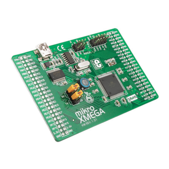
mikroXMEGA
™
Manual
All MikroElektronika´s development systems represent irreplaceable
tools for programming and developing microcontroller-based devices.
Carefully chosen components and the use of machines of the last
generation for mounting and testing thereof are the best guarantee of
high reliability of our devices. Due to simple design, a large number of
add-on modules and ready to use examples, all our users, regardless
of their experience, have the possibility to develop their projects in a
fast and efficient way.
MikroElektronika
Arrow.com.
Downloaded from
Advertisement
Table of Contents

Related Manuals for mikroElektronika mikroXMEGA MIKROE-580


Summary of Contents for mikroElektronika mikroXMEGA MIKROE-580
- Page 1 ™ Manual All MikroElektronika´s development systems represent irreplaceable tools for programming and developing microcontroller-based devices. Carefully chosen components and the use of machines of the last generation for mounting and testing thereof are the best guarantee of high reliability of our devices. Due to simple design, a large number of...
- Page 2 The CN4 (PDI) is used for programming/debugging via PDI interface. The CN5 (JTAG) connector is used for programming/debugging via JTAG interface. The CN1 and CN3 pads enable the microcontroller pins to be easily accessed. The 3.3V power supply voltage is supplied to the pads marked 3.3V (+3.3V) and GND. MikroElektronika Arrow.com. Arrow.com. Downloaded from...
- Page 3 PB7/TDO PB4/TMS RESET# VCC-3.3 PB5/TDI 22pF 22pF AVCC PB4/TMS PB5/TDI PR1/XTAL1 PR0/XTAL2 PB5/TCK PB7/TD0 ATXMEGA128A1 RESET# PQ1/TOSC2 PQ0/TOSC1 VCC-3.3 VCC-3.3 VCC-3.3 VCC-3.3 VCC-3.3 Figure 2: mikroXMEGA development system connection schematic MikroElektronika Arrow.com. Arrow.com. Arrow.com. Downloaded from Downloaded from Downloaded from...
- Page 4 Connect the development system to a PC via the USB connector CN2. Power the board via two pads 3.3V and GND. +3.3V power supply Ground Figure 5: Powering the board Figure 4: Programming the microcontroller MikroElektronika Arrow.com. Arrow.com. Arrow.com. Arrow.com. Downloaded from...
- Page 5 STEP 2: Starting up the mikroElektronika Bootloader program Download the mikroElektronika USB HID Bootloader program from Mikroelektronika’s website at: http://www.mikroe.com/eng/downloads/get/1271/mikrobootloader_xmega_v101.zip Unzip the file, then double click on the appropriate icon STEP 3: Program settings Click on the Change Settings button...
- Page 6 Click on the Open button STEP 6: Uploading the .hex file into the microcontroller Click on the Begin uploading button Follow the process of uploading in the progress bar MikroElektronika Arrow.com. Arrow.com. Arrow.com. Arrow.com. Arrow.com. Arrow.com.
- Page 7 After that, the microcontroller supplied on the development system has been programmed and ready for use. Click on the OK button MikroElektronika Arrow.com. Arrow.com. Arrow.com. Arrow.com. Arrow.com.
- Page 8 MikroElektronika Arrow.com. Arrow.com. Arrow.com. Arrow.com. Arrow.com. Arrow.com. Arrow.com. Arrow.com. Downloaded from Downloaded from Downloaded from Downloaded from Downloaded from Downloaded from Downloaded from Downloaded from...
Need help?
Do you have a question about the mikroXMEGA MIKROE-580 and is the answer not in the manual?
Questions and answers