Table of Contents
Advertisement
Quick Links
Line Follower
click
1. Introduction
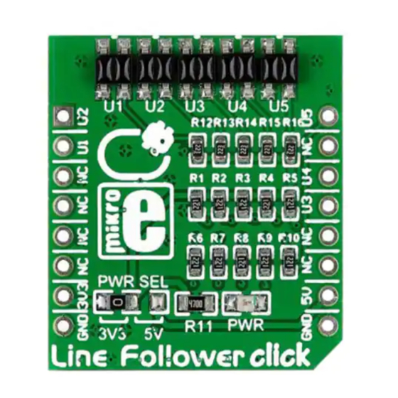
Line Follower click carries an array of five
QRE1113 miniature reflective object sensors.
For communicating with the target MCU, the
individual sensors have their own separate
digital outputs, each one routed through
a single mikroBUS™ pin: OUT1, OUT2,
OUT3, OUT4 and OUT5 (in place of default
mikroBUS™ pins RST, AN, PWM, TX and RX,
respectively). Line Follower click is designed
to use either a 3.3V or a 5V power supply.
2. Soldering the headers
Before using your click board
™
, make sure
to solder 1x8 male headers to both left and
right side of the board. Two 1x8 male headers
are included with the board in the package.
2
Turn the board upside down so that
the bottom side is facing you upwards.
Place shorter pins of the header into the
appropriate soldering pads.
1
3
Turn the board upward again. Make sure
to align the headers so that they are
perpendicular to the board, then solder the
pins carefully.
3. Plugging the board in
Once you have soldered the headers your
board is ready to be placed into the desired
mikroBUS
socket. Make sure to align the cut
™
in the lower-right part of the board with the
markings on the silkscreen at the mikroBUS
socket. If all the pins are aligned
correctly, push the board all the
way into the socket.
4. Essential features
As the name implies, Line Follower click is best
used for line following robots and cars. Each
one of the QRE1113 sensors consist of an
infrared transmitter and infrared receiver. By
default the sensor output a Logic Level 1, until
they encounter a white surface which changes
the output signal to 0. This is because white
surfaces are more reflective. Since there's
5 adjacent sensors, you can deduce the
position or thickness of the white line from the
combination of their outputs.
click
BOARDS
™
www.mikroe.com
™
Line Follower click Manual v101
0 1 0 0 0 0 0 0 9 0 4 5 9
Advertisement
Table of Contents

Related Manuals for mikroElektronika Line Follower click


Summary of Contents for mikroElektronika Line Follower click
- Page 1 Line Follower click 4. Essential features As the name implies, Line Follower click is best used for line following robots and cars. Each one of the QRE1113 sensors consist of an infrared transmitter and infrared receiver. By...
- Page 2 +3.3V QRE1113 QRE1113 QRE1113 QRE1113 QRE1113 9. Support MikroElektronika offers free tech support (www.mikroe.com/support) until the end of the product’s lifetime, so if something goes wrong, we’re ready and willing to help! 6. Dimensions 7. SMD jumper 10. Disclaimer Line...
Need help?
Do you have a question about the Line Follower click and is the answer not in the manual?
Questions and answers