Table of Contents
Advertisement
Advertisement
Table of Contents

Related Manuals for Bdcom S2928E


Summary of Contents for Bdcom S2928E
- Page 1 BDCOM S2928E Hardware Installation Manual...
-
Page 2: Table Of Contents
2.3.3 Cabinet Configuration ....................7 2.3.4 Power Requirements ....................7 2.4 Installation Tools and Device ....................7 Chapter 3 Installing the BDCOM S2928E Switch ................8 3.1 Installation Flow of BDCOM S2928E ................... 8 3.2 Installing the Machine Box of the Switch ................8 3.2.1 Installing the Machine Box on the Desk .............. - Page 3 Table of Contents Chapter 4 Maintaining Switch ......................14 4.1 Opening the Machine Box ....................14 4.2 Closing the Machine Box ....................15 Chapter 5 Hardware Fault Analysis ....................17 5.1 Fault Separation ......................... 17 5.1.1 Faults Relative with Power and Cooling System ............. 17 5.1.2 Faults Relative with Port, Cable and Connection ............
-
Page 4: Chapter 1 Bdcom S2928E Introduction
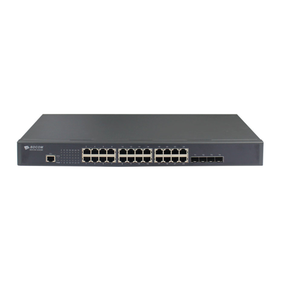
BDCOM S2928E. 1.1 Appearance Description for Standard Configuration The built-in ports of BDCOM S2928E are: 24 gigabit RJ45 ports, 4 10GE SFP+ ports, 1 console port. See table 1-1. Table 1-1 Attributes of the built-in port... -
Page 5: Bdcom S2928E Systematic Characteristic Parameters
BDCOM S2928E Hardware Installation Manual Figure 1-2 Back panel of the BDCOM S2928E switch Table 1-3 Parts at the back panel of the BDCOM S2928E switch Abbrev. Name Description Grounding column The grounding must be fine. ON means the power is switched on, while OFF Power switch means the power is cut off. -
Page 6: Rohs Description
BDCOM S2928E Hardware Installation Manual 1.3 ROHS Description - 3 -... -
Page 7: Chapter 2 Installation Preparation
Similar to other electronic products, the semiconductor chip easily gets damaged if you power on or off abruptly and frequently. To restart up the switch of BDCOM S2928E, you have to open the power switch after the power is cut down for three to five seconds. -
Page 8: Safety Notices
BDCOM S2928E Hardware Installation Manual 2.2.2 Safety Notices The safety notices mentioned here means that improper operation may lead to body damage. Read the installation guide carefully before you operate the system. Only professionals are allowed to install or replace the switch. -
Page 9: Electrostatic Discharge Damage Prevention
BDCOM S2928E Hardware Installation Manual C. Take proper measures to help persons who are hit by the disaster. Artificial respiration is needed if necessary. D. Seek for medical help, or judge the loss and seek for available help. 2.2.4 Electrostatic Discharge Damage Prevention Electrostatic discharge may damage devices and circuits. -
Page 10: Cabinet Configuration
2.4 Installation Tools and Device The tools and devices to install the BDCOM S2928E switch are not provided by the BDCOM S2928E switch. You yourself need to prepare them. The following are the tools and devices needed for the typical installation of the BDCOM S2928E switch: ... -
Page 11: Chapter 3 Installing The Bdcom S2928E Switch
Installing the machine box on the cabinet 3.2.1 Installing the Machine Box on the Desk The BDCOM S2928E switch can be directly put on the smooth and safe desk. Note: Do not put things weighing 4.5 kg or over 4.5 kg on the top of the switch. -
Page 12: Installing The Machine Box On The Cabinet
3.3 Connecting the Port 3.3.1 Connecting the Console port The switch of BDCOM S2928E switch has a console port. Its attributes and usage method are described in this section. The console port has a baud rate of 9600bps and a standard RJ45 plug, without the parity check and the flow control. - Page 13 Otherwise, the single-pass problem will arise on the super terminal. The cable is used to connect the console port of the BDCOM S2928E switch and the outside monitoring terminal device. One end is RJ45 port and the other end is 9-hole plug (DB9).
-
Page 14: Connecting 10Ge Sfp+ Ports
BDCOM S2928E Hardware Installation Manual 3.3.2 Connecting 10GE SFP+ Ports BDCOM S2928E provides with 4 10GE SFP+ ports, which corresponds to TE1~TE4. You can insert the SFP+ module and then connect it to other Ethernet terminal devices through the optical fiber if you want to use the 10GE SFP+ port. - Page 15 BDCOM S2928E Hardware Installation Manual Because 24 10/100/1000Base-T ports of BDCOM S2928E support the MDI/MDIX self-identification of the cable, 2952P can adopt 5-type direct-through/cross network cables when it connects other Ethernet terminals. Figure 3-6 1000Base-TX ports connect to other Ethernet terminal devices Caution: The device shown in the above figure does not represent the material BDCOM S2928E.
-
Page 16: Checking After Installation
BDCOM S2928E Hardware Installation Manual 3.4 Checking after Installation Before electrically starting up the switch, perform the following checkups after the switch is installed: If the switch is installed on the cabinet, check whether the installation point between the cabinet and the switch is strong. If the switch is installed on the desk, check whether there is enough space for the switch to discharge its heat and whether the desk is stable. -
Page 17: Chapter 4 Maintaining Switch
BDCOM S2928E Hardware Installation Manual Chapter 4 Maintaining Switch Caution: Before opening the chassis, make sure you have discharged the static electricity on your body and turned off the power of the switch. Before performing operations beside the power source or on the machine box, please plug out the power cable. -
Page 18: Closing The Machine Box
BDCOM S2928E Hardware Installation Manual Caution: The device shown in the above figure does not represent the material BDCOM S2928E. (5) When the cover is opened, put it aside. The mainboard of the system appears. Note: After taking off the cover, put it horizontally and avoid it to be crushed or collided. - Page 19 BDCOM S2928E Hardware Installation Manual According to the figure above, put close the edges of bottom shell and the cover. When the cover and the bottom are closely tied, let the cover slide the slot of the front panel at the bottom.
-
Page 20: Chapter 5 Hardware Fault Analysis
BDCOM S2928E Hardware Installation Manual Chapter 5 Hardware Fault Analysis The part describes how to remove the fault from the switch. 5.1 Fault Separation The key for resolving the systematic faults is to separate the fault from the system. You can compare what the system is doing with what the system should do to detect the fault. -
Page 21: Indicator Description
BDCOM S2928E Hardware Installation Manual 5.2 Indicator Description The following table shows the indicators of the BDCOM S2928E switch and their description: Abbrev. Name Description Power indicator When the switch is powered on, the indicator is on. When the indicator is always on, the system is being started up.
Need help?
Do you have a question about the S2928E and is the answer not in the manual?
Questions and answers