Table of Contents
Advertisement
Advertisement
Table of Contents

Related Manuals for Bdcom S2956 series


Summary of Contents for Bdcom S2956 series
- Page 1 S2956 Hardware Installation Manual...
-
Page 2: Table Of Contents
Table of Contents Table of Contents Chapter 1 S2956 Switch Intro ................1 1.1 Standard Configuration ................1 1.2 Characteristic Parameters of S2956 ............2 Chapter 2 Installation Preparation ................ 4 2.1 Cautions .................... 4 2.2 Safety Advice ..................4 2.2.1 Safety Principles................ -
Page 3: Chapter 1 S2956 Switch Intro
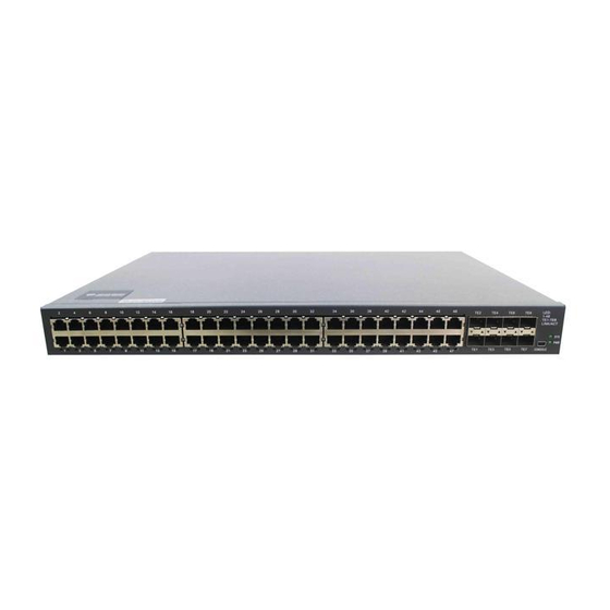
S2956 Hardware Installation Manual Chapter 1 S2956 Switch Intro The document describes the characteristics and parameters of S2956 and gives an overview of S2956 . Standard Configuration The accessory ports of S2956 are formed of 48 1000M-Ethernet RJ45 ports, 8 10G SFP+ ports and one console port. -
Page 4: Characteristic Parameters Of S2956
S2956 Hardware Installation Manual Figure 1-2 Back template of the S2956 switch Table 1-3 Parts at the back template of the S2956 switch Abbrev. Name Remarks AC power socket 100 to 240V AC ON: means it is powered on; OFF: AC power switch means it is powered off. - Page 5 S2956 Hardware Installation Manual ℃ 0℃-40 ; 10% -85% non-condensing Working temperature/humidity ℃ -40℃-80 ; 5% -95% non-condensing Storage temperature/ humidity Input voltage: AC100-240V Power Source’s Characteristics Input frequency: 47-63Hz Input current: 1.5A Output voltage: 12VDC Output current: 6A Power consumption in full load 4.2Kg Net weight...
-
Page 6: Chapter 2 Installation Preparation
S2956 Hardware Installation Manual Chapter 2 Installation Preparation Cautions Similar to other electronic products, the semiconductor chip easily gets damaged if you power on and off abruptly and frequently. To restart up the switch of S2956, you have to open the power on-off three or five seconds after the power is cut off. Avoid severe collision or falling down from the height to protect the parts in the switch. -
Page 7: Safety Principles For Live Working
S2956 Hardware Installation Manual Pull out the AC power socket and close the direct-current power before operating on the chassis or working beside the power source. The final configuration of products must comply with relative national laws and regulations. 2.2.3 Safety Principles for Live Working When you work under electricity, following the following principles: Put off ornaments, such as ring, necklace, watch and bracelet, before you operate under live working. -
Page 8: Electrostatic Discharge Prevention
S2956 Hardware Installation Manual 2.2.4 Electrostatic Discharge Prevention Electrostatic discharge may damage devices and circuits. Improper treatment may cause the switch to malfunction completely or discontinuously. Move or locate the devices according to the measures of electrostatic discharge prevention, ensuring the chassis connects the ground. Another measure is to wear the static-proof hand ring. -
Page 9: Power Requirements
S2956 Hardware Installation Manual Ensure that nice ventilation is provided for the devices installed at the bottom of the cabinet. The clapboard separates exhaust gas and inflow air, and boost the cool air to flow in the chassis. The best location of the clapboard is decided by the air flow mode in the chassis, which can be obtained through different location tests. -
Page 10: Chapter 3 Installing S2956
S2956 Hardware Installation Manual Chapter 3 Installing S2956 Caution: Only professionals are allowed to install or replace the devices of the switch. Installation Flow of S2956 Installing the Chassis of the Switch The chassis of the router can be installed on the desk or can be fixed to other cabinets. Your network installation requirements can be met if you conduct the operations according to the following procedure. -
Page 11: Installing The Chassis On The Desk
S2956 Hardware Installation Manual 3.2.1 Installing the Chassis on the Desk S2956 can be directly put on the smooth and safe desk. Note: Do not put things weighing 4.5 kg or over 4.5 kg on the top of the switch. 3.2.2 Installing the Chassis on the Cabinet The chassis of the switch is fixed on the cabinet through the brackets. - Page 12 S2956 Hardware Installation Manual set to a rate of 9600bps, eight data bits, one stop bit, no sum check bit and traffic control. Figure 3-3 Connecting the console port of S2956 and computer Note: The switch shown in the previous figure does not represent real S2956 switch. Table 3-1 Definition of the pins of the console port Name Symbol...
-
Page 13: Connecting The 1000M Ethernet Sfp Port
S2956 Hardware Installation Manual Figure 3-4 External wiring of the console port 3.3.2 Connecting the 1000M Ethernet SFP Port S2956 provides 8 10G SFP+ ports. You can insert the SFP+ optical module into the port and then connect the module to other Ethernet terminal devices through the optical fiber if you want to use the SFP+ port. - Page 14 S2956 Hardware Installation Manual Figure 3-5 RJ-45 connector of Ethernet TX port Because 10/100/1000Base-T ports S2956 support MDI/MDIX auto-identification of the cable, S2956 can adopt five classes of direct-through/cross network cables when it connects other Ethernet terminals. Figure 3-6 Connecting the 1000Base-TX port and other Ethernet terminals Note: The switch shown in the previous figure does not represent real S2956 switch.
-
Page 15: Checkup After Installation
S2956 Hardware Installation Manual the paraphase of data 1 Receiving and transmitting TP3+ the normal phase of data 3 Receiving and transmitting TP3- the paraphase of data 3 The direct-through or cross network cable has the function of auto-identification, so the five classes of direct-through/cross network cables can be used to connect other Ethernet devices. -
Page 16: Chapter 4 Maintaining The Switch
S2956 Hardware Installation Manual Chapter 4 Maintaining the Switch Caution: Before opening the chassis, make sure that you have released the static you carried and then turn off the power on-off of the switch. Before operating any step in Appendix B, read the section “Safety Advice”. Before performing operations beside the power source or on the chassis, turn off the power on-off and plug out the power cable. -
Page 17: Closing The Chassis
S2956 Hardware Installation Manual Note: The switch shown in the previous figure does not represent real S2956 switch. When the cover is opened, put it aside. The mainframe of the system appears. Note: After taking off the cover, put it horizontally and avoid it to be crushed or collided. Otherwise, the chassis is hard to install. -
Page 18: Chapter 5 Hardware Fault Analysis
S2956 Hardware Installation Manual Chapter 5 Hardware Fault Analysis The part describes how to remove the fault from the switch. Fault Separation The key for resolving the systematic faults is to separate the fault from the system. You can compare what the system is doing with what the system should do to detect the fault. - Page 19 S2956 Hardware Installation Manual If the switch is powered on, the indicator Power LED is on. If the indicator is always on, the system is being started. System LED If the LED flickers, the system works normally. If the LED is always on, the link on the port is normal.
Need help?
Do you have a question about the S2956 series and is the answer not in the manual?
Questions and answers