Table of Contents
Advertisement
Quick Links
Advertisement
Table of Contents

Related Manuals for Bdcom S3756F


Summary of Contents for Bdcom S3756F
- Page 1 BDCOM S3756F Hardware Installation Manual...
-
Page 2: Table Of Contents
Table of Contents ..........................I Chapter 1 BDCOM S3756F Switch ....................1 1.1 Appearance Description for Standard Configuration ............1 1.2 BDCOM S3756F Systematic Characteristic Parameters ............. 2 1.3 ROHS Description ........................ 4 Chapter 2 Installation Preparation ..................... 5 2.1 Caution of Usage ......................... 5 2.2 Safety Advice ........................ - Page 3 Table of Contents 3.3.1 Connecting the Console Port ................... 11 3.3.2 Connecting 10G Ethernet SFP+ Ports ..............13 3.3.3 Connecting Gigabit Ethernet TX Ports ..............14 3.3.4 Connecting Gigabit SFP Ports ................. 15 1.4 Checking after Installation ....................15 Chapter 4 Maintaining Switch ......................17 4.1 Opening the Machine Box ....................
-
Page 4: Chapter 1 Bdcom S3756F Switch
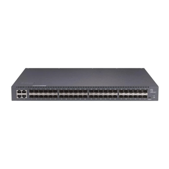
BDCOM S3756F. 1.1 Appearance Description for Standard Configuration The built-in ports of BDCOM S3756F are: 4 gigabit combo ports, 44 gigabit Ethernet optical ports, 8 10G Ethernet SFP+ ports, 1 Console port. See table 1-1. Table 1-1 Attributes of the built-in port... -
Page 5: Bdcom S3756F Systematic Characteristic Parameters
If the switch is powered on, the indicator is Power indicator Additionally, BDCOM S3756F has 8 10G optical ports, 1 grounding column, 1 power socket at its back. Figure 1-2 The back template of the BDCOM S3756F switch Table 1-3 Parts at the back template of the BDCOM S3756F switch Abbrev. - Page 6 BDCOM S3756F Hardware Installation Manual RFC 1157 SNMP v1/v2 RFC 1213 MIB II Network management standard RFC 1757 RMON 1,2,3,9 Flash Memory: 16M Bytes Memory SDRAM: 512Mbytes; 4 gigabit COMBO ports 44 gigabit Ethernet SFP ports Standard configuration 8 10G Ethernet SFP+ ports 1 Console port 442.50×350×44...
-
Page 7: Rohs Description
BDCOM S3756F Hardware Installation Manual 1.3 ROHS Description - 4 -... -
Page 8: Chapter 2 Installation Preparation
Similar to other electronic products, the semiconductor chip easily gets damaged if you power on or off abruptly and frequently. To restart up the switch of BDCOM S3756F, you have to open the power on-off after the power is cut down for three to five seconds. -
Page 9: Safety Principles For Live Working
BDCOM S3756F Hardware Installation Manual Read the installation guide carefully before you operate the system. Only professionals are allowed to install or replace the switch. Pull out the AC power socket and close the direct-current power before operating on the machine box or working beside the power source. -
Page 10: Electrostatic Discharge Damage Prevention
BDCOM S3756F Hardware Installation Manual 2.2.4 Electrostatic Discharge Damage Prevention Electrostatic discharge may damage devices and circuits. Improper treatment may cause the switch to malfunction completely or discontinuously. Move or locate the devices according to the measures of electrostatic discharge prevention, ensuring the machine box connects the ground. -
Page 11: Cabinet Configuration
2.4 Installation Tools and Device The tools and devices to install the BDCOM S3756F switch are not provided by the BDCOM S3756F switch. You yourself need to prepare them. The following are the tools and devices needed for the typical installation of the BDCOM S3756F switch: ... - Page 12 BDCOM S3756F Hardware Installation Manual Static armguard Bolt Ethernet cable Other Ethernet terminal devices Control terminal - 9 -...
-
Page 13: Chapter 3 Installing The S3756F Switch
Installing the machine box on the desk Installing the machine box on the cabinet 3.2.1 Installing the Machine Box on the Desk The BDCOM S3756F switch can be directly put on the smooth and safe desk. - 10 -... -
Page 14: Installing The Machine Box On The Cabinet
USB plug. After you connect the console port to the serial port of PC through a console cable, you can configure and monitor the switch of BDCOM S3756F by running a terminal emulation software, such as super Windows terminal. The cable is provided according to the host. The... - Page 15 One end of the cable is a mini USB plug and the other end is a 9-hole plug (DB9). The Mini USB plug is put into the socket of the console port on BDCOM S3756F. The inner line connection in the cable is shown in figure 3-4.
-
Page 16: Connecting 10G Ethernet Sfp+ Ports
No connect Note: The console port of the BDCOM S3756F switch does not support traffic control. Therefore, you must set the option data traffic control to none when you configure the switch with the super terminal. Otherwise, the single-pass problem will arise on the super terminal. -
Page 17: Connecting Gigabit Ethernet Tx Ports
BDCOM S3756F Hardware Installation Manual 3.3.3 Connecting Gigabit Ethernet TX Ports BDCOM S3756F provides 4 10/100/1000 Base-T ports. Ports G1-G4 are combo ports. Each port has its corresponding indicator:1-4. The indicators are used to indicate the LINK/ACT state. The ports can connect other Ethernet terminal devices through the UTP port and the direct-through or cross network cable. -
Page 18: Connecting Gigabit Sfp Ports
TP3- 3.3.4 Connecting Gigabit SFP Ports BDCOM S3756F provides 48 gigabit SFP ports. G1-G4 ports are combo ports. You can connect the SFP optical module to the SFP port and then you can connect other Ethernet terminal devices through the optical cable. - Page 19 BDCOM S3756F Hardware Installation Manual Check whether the connected power meets the power requirements of the switch. Check whether the grounding line is correctly connected. Check whether the switch is correctly connected to other terminal devices. - 16 -...
-
Page 20: Chapter 4 Maintaining Switch
BDCOM S3756F Hardware Installation Manual Chapter 4 Maintaining Switch Caution: Before opening the machine box, make sure that you have released the static you carried and then turn off the power on-off of the switch. Before operating any step in Appendix B, read the section “Safety Advice”. -
Page 21: Closing Machine Box
BDCOM S3756F Hardware Installation Manual When the cover is opened, put it aside. The mainboard of the system appears. Note: After taking off the cover, put it horizontally and avoid it to be crushed or collided. Otherwise, the machine box is hard to install. -
Page 22: Chapter 5 Hardware Fault Analysis
BDCOM S3756F Hardware Installation Manual Chapter 5 Hardware Fault Analysis The part describes how to remove the fault from the switch. 5.1 Fault Separation The key for resolving the systematic faults is to separate the fault from the system. You can compare what the system is doing with what the system should do to detect the fault. -
Page 23: Indicator Description
9600 bps, eight data bits, no sum check bit, one stop bit and no traffic control. 5.2 Indicator Description The following table shows the indicators of the BDCOM S3756F switch and their description: Abbrev. Name... - Page 24 BDCOM S3756F Hardware Installation Manual Disclaimer of warranty provides no evident or hinted guarantee towards the contents of this manual. In no event, except for the company’s breach of law, shall the company be liable for incidental, consequential, indirect or special damages of any kind or for loss of profits or revenue or loss of business arising out of or relating to this manual.
Need help?
Do you have a question about the S3756F and is the answer not in the manual?
Questions and answers