Table of Contents
Advertisement
Advertisement
Table of Contents

Related Manuals for Bdcom S2528-B


Summary of Contents for Bdcom S2528-B
- Page 1 S2528-B Hardware Installation Manual...
-
Page 2: Table Of Contents
2.3.3 Cabinet Configuration......................6 2.3.4 Power Requirements......................7 2.4 Installation Tools and Device......................7 Chapter 3 Installing the S2528-B Switch..................... 8 3.1 Installation Flow of S2528-B......................8 3.2 Installing the Machine Box of the Switch..................8 3.2.1 Installing the Machine Box on the Desk................8 3.2.2 Installing the Machine Box on the Cabinet................9... - Page 3 Table of Contents 3.4 Checking After Installation......................12 Chapter 4 Maintaining Switch........................14 4.1 Opening the Machine Box......................14 4.2 Closing the Machine Box.......................15 Chapter 5 Hardware Fault Analysis......................17 5.1 Fault Separation..........................17 5.1.1 Faults Relative with Power and Cooling System............17 5.1.2 Faults Relative with Port, Cable and Connection............17 5.2 Indicator Description........................
-
Page 4: Chapter 1 S2528-B Introduction
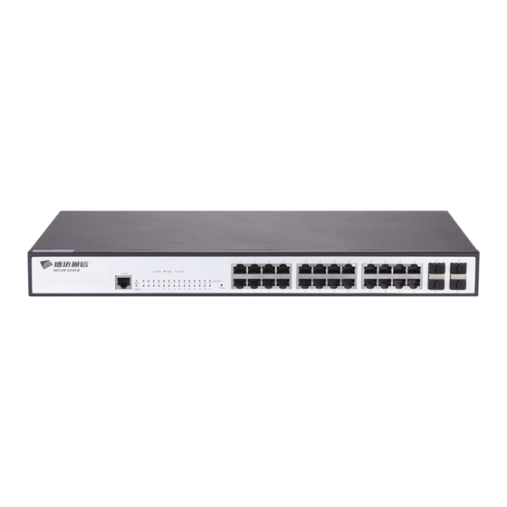
The section describes the characteristics and parameters of S2528-B and gives an overview of S2528-B. 1.1 Appearance Description for Standard Configuration The built-in ports of S2528-B are: 24 gigabit Ethernet Base-T ports, 4 gigabit Ethernet SFP ports and 1 Console port. See table 1-1. Port... -
Page 5: S2528-B Systematic Characteristic Parameters
4 SFP ports signals. Table 1- 2 Parts at the front template of the S2528-B switch Besides, S2528-B has a grounding column and a power socket at its back. Figure 1- 2 Back template of the S2528-B switch Abbrev. Name... - Page 6 S2528-B Hardware Installation Manual RFC 1157 SNMP v1/v2 Network management RFC 1213 MIB II standard RFC 1757 RMON 1,2,3,9 Flash Memory: 16M Bytes Memory DDR3: 128M Bytes; 4 gigabit SFP ports Standard 1 Console port configuration 24 gigabit Base-T ports Dimensions 440×232×44...
-
Page 7: Chapter 2 Installation Preparation
Similar to other electronic products, the semiconductor chip easily gets damaged if you power on or off abruptly and frequently. To restart up the switch of S2528-B, you have to open the power on-off after the power is cut down for three to five seconds. -
Page 8: Safety Principles For Live Working
S2528-B Hardware Installation Manual Read the installation guide carefully before you operate the system. Only professionals are allowed to install or replace the switch. Pull out the AC power socket and close the direct-current power before operating on the machine box or working beside the power source. -
Page 9: Electrostatic Discharge Damage Prevention
S2528-B Hardware Installation Manual 2.2.4 Electrostatic Discharge Damage Prevention Electrostatic discharge may damage devices and circuits. Improper treatment may cause the switch to malfunction completely or discontinuously. Move or locate the devices according to the measures of electrostatic discharge prevention, ensuring the machine box connects the ground. Another measure is to wear the static-proof hand ring. -
Page 10: Power Requirements
2.4 Installation Tools and Device The tools and devices to install the S2528-B switch are not provided by the S2528-B switch. You yourself need to prepare them. The following are the tools and... -
Page 11: Chapter 3 Installing The S2528-B Switch
Installing the machine box on the cabinet 3.2.1 Installing the Machine Box on the Desk The S2528-B switch can be directly put on the smooth and safe desk. Note: Do not put things weighing 4.5 kg or over 4.5 kg on the top of the switch. -
Page 12: Installing The Machine Box On The Cabinet
RJ45 plug. After you connect the console port to the serial port of PC through a console cable, you can configure and monitor the switch of S2528-B by running the terminal emulation software, such as super Windows terminal. The cable is provided according to the host. - Page 13 Otherwise, the single-pass problem will arise on the super terminal. The cable is used to connect the console port of the S2528-B switch and the outside console terminal device. One end of the console port is RJ45 8-core plug and the other end of the console port is a 25-hole plug and a 9-hole plug.
-
Page 14: Connecting Gigabit Ethernet Sfp Ports
Figure 3- 5 Cable connection at the console port 3.3.2 Connecting Gigabit Ethernet SFP Ports The S2528-B switch has 4 gigabit SFP ports. Each port has a corresponding indicator for showing their LINK/ACT state. If the indicator is always on, the port is normally linked;... -
Page 15: Checking After Installation
S2528-B Hardware Installation Manual Because 24 10/100/1000Base-T ports of S2528-B support the MDI/MDIX self-identification of the cable, S2528-B can adopt five types of direct-through/cross network cables when it connects other Ethernet terminals. Figure 3-8 Connecting the 1000M Base-T port and other Ethernet terminals Pin name Abbr. - Page 16 S2528-B Hardware Installation Manual If the switch is installed on the cabinet, check whether the installation point between the cabinet and the switch is strong. If the switch is installed on the desk, check whether there is enough space for the switch to discharge its heat and whether the desk is stable.
-
Page 17: Chapter 4 Maintaining Switch
S2528-B Hardware Installation Manual Chapter 4 Maintaining Switch Caution: Before opening the machine box, make sure that you have released the static you carried and then turn off the power on-off of the switch. Before operating any step in Appendix B, read the section “Safety Advice”. -
Page 18: Closing The Machine Box
S2528-B Hardware Installation Manual Figure 4-1 Opening the chassis of S2528-B When the cover is opened, put it aside. The mainboard of the system appears. Note: After taking off the cover, put it horizontally and avoid it to be crushed or collided. - Page 19 S2528-B Hardware Installation Manual When the cover and the bottom are closely tied, let the cover slide the slot of the front template at the bottom. Nail the bolt and screw it tightly with the screwdriver. Reinstall the switch on the cabinet or the desk.
-
Page 20: Chapter 5 Hardware Fault Analysis
9600 bps, eight data bits, no sum check bit, one stop bit and no traffic control. 5.2 Indicator Description The following table shows the indicators of the S2528-B switch and their description: - 17 -... - Page 21 If the indicator is on in green: 1000Mbps If the indicator is off, the port is not connected. Table 5-1 Definition of S2528-B Switch Indicator Copyright Claims Without the written approval of the company , any person or group cannot transcribe, copy or change partial or all contents of this manual, and must not broadcast it in any manner.
Need help?
Do you have a question about the S2528-B and is the answer not in the manual?
Questions and answers