Table of Contents
Advertisement
Advertisement
Table of Contents

Related Manuals for Bdcom S2528GX


Summary of Contents for Bdcom S2528GX
- Page 1 S2528GX Hardware Installation Manual...
-
Page 2: Table Of Contents
2.3.3 Cabinet Configuration..........................6 2.3.4 Power Requirements..........................7 2.4 Installation Tools and Device ..........................7 Chapter 3 Installing the S2528GX Switch ......................... 8 3.1 Installation Flow of S2528GX..........................8 3.2 Installing the Chassis of the Switch........................8 3.2.1 Installing the Machine Box on the Desk ....................9 3.2.2 Installing the Chassis on the Cabinet...................... -
Page 3: Chapter 1 Overview Of S2528Gx Switch
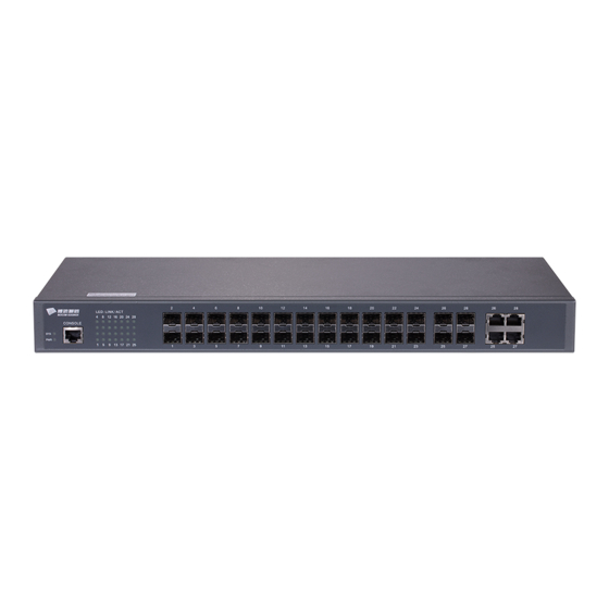
The document describes the characteristics and parameters of S2528GX and gives an overview of S2528GX. 1.1 Standard Configuration S2528GX has 24 gigabit SFP ports, 4 TX/SFP ports, 1 console port and 1 Phone Jack power-supply port. For details, see table 1-1. Table 1-1 Attributes of the necessary port... -
Page 4: Attribute Parameters Of S2528Gx
S2528GX Hardware Installation Manual Figure 1-2 Back template of the S2528GX switch Table 1-3 Parts at the back template of the S2528GX switch Abbrev. Name Remarks None AC power socket 100 to 240V AC None Grounding The grounding must be fine. - Page 5 S2528GX Hardware Installation Manual 440*180*44mm Specifications ℃ ℃ to 60 ; 10% -85% non-condensing Working temperature/humidity ℃ ℃ to 80 ; 5% -95% non-condensing Storage temperature/ humidity Input voltage: 220V AC Power specifications <40W Power consumption - 3 -...
-
Page 6: Chapter 2 Installation Preparation
Similar to other electronic products, the semiconductor chip easily gets damaged if you power on and off abruptly and frequently. To restart up the switch of S2528GX, you have to open the power on-off three or five seconds after the power is cut off. -
Page 7: Safety Principles For Live Working
S2528GX Hardware Installation Manual Pull out the AC power socket and close the direct-current power before operating on the chassis or working beside the power source. The final configuration of products must comply with relative national laws and regulations. -
Page 8: Electrostatic Discharge Prevention
S2528GX Hardware Installation Manual 2.2.4 Electrostatic Discharge Prevention Electrostatic discharge may damage devices and circuits. Improper treatment may cause the switch to malfunction completely or discontinuously. Move or locate the devices according to the measures of electrostatic discharge prevention, ensuring the chassis connects the ground. Another measure is to wear the static-proof hand ring. -
Page 9: Power Requirements
2.4 Installation Tools and Device The tools and devices to install the S2528GX switch are not provided by the S2528GX switch. You yourself need to prepare them. The following are the tools and devices needed for the typical installation of the S2528GX switch: ... -
Page 10: Chapter 3 Installing The S2528Gx Switch
S2528GX Hardware Installation Manual Chapter 3 Installing the S2528GX Switch Caution: Only professionals are allowed to install or replace the devices of the switch. Installation Flow of S2528GX 3.2 Installing the Chassis of the Switch The chassis of S2008WS-B can be installed on the desk or can be fixed to other cabinets. -
Page 11: Installing The Machine Box On The Desk
S2528GX Hardware Installation Manual 3.2.1 Installing the Machine Box on the Desk The S2528GX switch can be directly put on the smooth and safe desk. Note: Do not put things weighing 4.5 kg or over 4.5 kg on the top of the switch. - Page 12 RJ45 plug. After you connect the console port to the serial port of PC through a console cable, you can configure and monitor the switch of S2528GX by running a terminal emulation software, such as super Windows terminal. The cable is provided according to the host.
-
Page 13: Connecting Gigabit Sfp Ports
9-hole plug (DB9). The RJ45 plug is put into the socket of the console port on the S2528GX switch. The inner line connection in the cable is shown in figure 3-1. The console cable is numbered as RLC0301. -
Page 14: Connecting Ethernet Tx Port
S2528GX Hardware Installation Manual Note: The switch shown in the previous figure does not represent real S2528GX switch. 3.3.3 Connecting Ethernet TX Port The S2528GX switch has 24 10/100/1000Base-T ports. The LEDs are labeled with numbers 1-24, indicating the link/ACT state of the port. You can connect other Ethernet terminal devices to the UTP port through the cut-through or cross network cable. - Page 15 S2528GX Hardware Installation Manual Figure 3-7 Connecting the 1000Base-TX port and other Ethernet terminals Note: The switch shown in the previous figure does not represent real S2528GX switch. Table 3-2 Definition of the pins of the 1000M RJ45 port Pin name...
-
Page 16: Checkup After Installation
S2528GX Hardware Installation Manual The direct-through or cross network cable has the function of auto-identification, so the five classes of direct-through/cross network cables can be used to connect other Ethernet devices. 3.4 Checkup After Installation Before electrically starting up the switch, perform the following checkups after the switch is installed: ... -
Page 17: Chapter 4 Maintaining The Switch
S2528GX Hardware Installation Manual Chapter 4 Maintaining the Switch Caution: Before opening the chassis, make sure that you have released the static you carried and then turn off the power on-off of the switch. Before operating any step in Appendix B, read the section “Safety Advice”. -
Page 18: Closing Chassis
S2528GX Hardware Installation Manual Note: The switch shown in the previous figure does not represent real S2528GX switch. Put the chassis aside after you open it. The main board of the system appears. Note: After taking off the chassis, put it horizontally and avoid it to be crushed or collided. -
Page 19: Chapter 5 Hardware Fault Analysis
9600 bps, eight data bits, no sum check bit, one stop bit and no traffic control. 5.2 LED description The LED shows that the switch is running. The following table shows the LEDs of the S2528GX switch and their description: Abbrev. Name Remarks... - Page 20 S2528GX Hardware Installation Manual If the switch is powered on, the LED is Power LED If the LED is always on, the system is being started. System LED If the LED flickers, the system works normally. If the LED is always on, the link on the port is normal.
Need help?
Do you have a question about the S2528GX and is the answer not in the manual?
Questions and answers