Table of Contents
Advertisement
Quick Links
Advertisement
Table of Contents

Related Manuals for Bdcom S2518PB


Summary of Contents for Bdcom S2518PB
- Page 1 S2518PB Hardware Installation Manual...
-
Page 2: Table Of Contents
2.3.2 Location Configuration Prevention..................7 2.3.3 Cabinet Configuration......................7 2.3.4 Power Requirements......................7 2.4 Installation Tools and Device......................7 Chapter 3 Installing the S2518PB Switch..................... 8 3.1 Installation Procedures of S2518PB....................8 3.2 Installing the Chassis of S2518PB....................8 3.2.1 Installing the Chassis on the Desk..................8 3.2.2 Installing the Chassis on the Cabinet................. -
Page 3: Chapter 1 S2518Pb Switch Overview
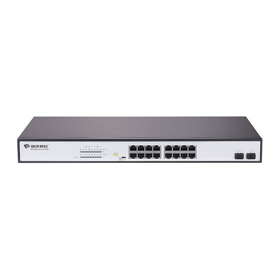
S2518PB Hardware Installation Manual Chapter 1 S2518PB Switch Overview The document describes the characteristics and parameters of S2518PB and gives an overview of S2518PB. 1.1 Standard Configuration S2518PB switch has three parts: 16 IEEE802.3af/at gigabit Ethernet Base-T ports, 2 gigabit Ethernet SFP ports and 1 Console port. See the following table:... - Page 4 2 SFP ports optical signals. Besides, S2518PB provides with a grounding column and a power socket. Figure 1- 2 Back template of the S2518PB switch Table 1- 3 Parts at the rear template of the S2518PB switch Abbrev. Name Remarks Grounding column The grounding must be fine.
-
Page 5: Characteristic Parameters Of S2518Pb
S2518PB Hardware Installation Manual 1.2 Characteristic Parameters of S2518PB IEEE 802.1d Spanning Tree Protocol IEEE 802.1p Class of Service IEEE 802.1q tagged VLAN IEEE 802.3x Flow control Supported standard IEEE 802.3ad Link aggregation IEEE802.3af Power over Ethernet Protocol IEEE 802.3at Power over Ethernet Plus... -
Page 6: Rohs Description
S2518PB Hardware Installation Manual 1.3 ROHS Description - 4 -... -
Page 7: Chapter 2 Installation Preparation
Similar to other electronic products, the semiconductor chip easily gets damaged if you power on and off abruptly and frequently. To restart up the switch of S2518PB, you have to open the power on-off three or five seconds after the power is cut off. -
Page 8: Electrostatic Discharge Damage Prevention
S2518PB Hardware Installation Manual Put off ornaments, such as ring, necklace, watch and bracelet, before you operate under live working. When metal articles connect the power to the ground, short circuit happens and components may be damaged. Please cut off the direct-current connection when you operate the hull or work near the power supply. -
Page 9: Location Configuration Prevention
2.4 Installation Tools and Device The tools and devices to install the S2518PB switch are not provided by the S2518PB switch. You yourself need to prepare them. The following are the tools and devices needed for the typical installation of the S2518PB switch: ... -
Page 10: Chapter 3 Installing The S2518Pb Switch
Installing the Chassis on the Cabinet 3.2.1 Installing the Chassis on the Desk The S2518PB switch can be directly put on the smooth and safe desk. Note: Do not put things weighing 4.5 kg or over 4.5 kg on the top of the switch. -
Page 11: Connecting The Port
3.3.1 Connecting the Console Port The switch of S2518PB has a Console port. The rate of the console port is a value of 1200bps—115200bps. It has a standard RJ45 plug. After you connect the console port to the serial port of PC through a console cable, you can configure and monitor the switch of S2518PB by running a terminal emulation software, such as super Windows terminal. - Page 12 25-hole plug (DB25) and a 9-hole plug (DB9). The RJ45 plug is put into the socket of the console port on the S2518PB switch. DB25 or DB9 is applied according to the requirement of the terminal serial port. The inner line connection in the cable is shown in Figure 3-5.
-
Page 13: Connecting The Sfp Ports
3.3.2 Connecting the SFP Ports S2518PB provides 2 gigabit SFP optical ports. Each port corresponds to one indicator respectively, which is used for indicating the port Link/ACT state. When the indicator is always on, the link is normal; when it flickers, the data receives and forwards. To use the optical port, you need connect it to the SFP optical module, and then to other Ethernet terminal devices through an optical fiber. - Page 14 S2518PB Hardware Installation Manual Figure 3-7 RJ-45 connector of the console port Because 16 10/100/1000 Base-Base-T ports of S2518PB support the MDI/MDIX auto-identification of the cable,S2518PB can adopt five classes of direct-through/cross network cables when it connects other Ethernet terminals.
-
Page 15: Checkup After Installation
Check whether the connected power supply meets the power requirements of the switch. Check whether the grounding line of S2518PB is correctly connected. Check whether S2518PB is correctly connected to other terminal devices. ... -
Page 16: Chapter 4 S2518Pb Maintenance
Caution: Before opening the chassis, make sure that you have released the static you carried and then turn off the power on-off of S2518PB. Before operating any step in Appendix B, read the section “Safety Advice”. Before performing operations beside the power supply or on the chassis, turn off the power on-off and plug out the power cable. -
Page 17: Closing The Chassis
S2518PB Hardware Installation Manual When the cover is opened, put it aside. The main board of the system appears. Note: After taking off the cover, put it horizontally and avoid it to be crushed or collided. Otherwise, the chassis is hard to install. -
Page 18: Chapter 5 Hardware Fault Analysis
9600 bps, eight data bits, no sum check bit, one stop bit and no traffic control. 5.2 LED Description The LED shows that the switch is running. The following table shows the LEDs of the S2518PB switch and their description: Table 5-1 Definitions of Switch Indicators Abbrev. Name... - Page 19 S2518PB Hardware Installation Manual normally. If the indicator is on in red, it is 10/100Mbps. If the indicator is on in green, it is LINK/ACT port indicators 1000Mbps. If the indicator is off, it does not connect to the network.
Need help?
Do you have a question about the S2518PB and is the answer not in the manual?
Questions and answers