Table of Contents
Advertisement
Advertisement
Table of Contents

Related Manuals for Bdcom S2510-B


Summary of Contents for Bdcom S2510-B
- Page 1 S2510-B Hardware Installation Manual...
-
Page 2: Table Of Contents
2.3.3 Cabinet Configuration......................6 2.3.4 Power Requirements......................7 2.4 Installation Tools and Device......................7 Chapter 3 Installing the S2510-B Switch...................... 8 3.1 Installation Procedure of S2510-B....................8 3.2 Installing the Chassis of S2510-B....................8 3.2.1 Installing the Chassis on the Desk..................8 3.2.2 Installing the Chassis on the Cabinet................. -
Page 3: Chapter 1 S2510-B Switch
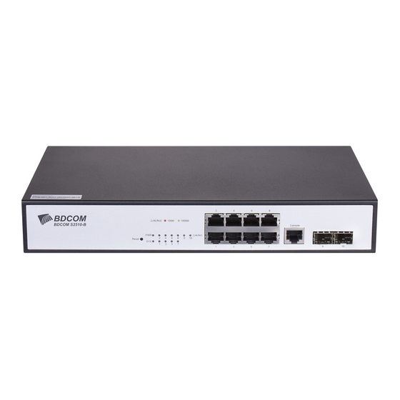
The document describes the characteristics and parameters of S2510-B and gives an overview of S2510-B. 1.1 Standard Configuration S2510-B has three parts: 8 gigabit Base-T ports and 2 gigabit SFP ports and 1 console port, as shown in the following table: Table 1- 1 Attributes of the accessory port... -
Page 4: Characteristic Parameters Of S2510-B
2 SFP ports Forwards the 1000M Ethernet optical signals. Additionally, S2510-B has a grounding column, a socket and a soundless fan at its back Figure 1- 2 Back template of the S2510-B switch Table 1- 2 Parts at the back template of the S2510-B switch Abbrev. - Page 5 S2510-B Hardware Installation Manual Memory Flash Memory: 16M Mbytes DDR3: 128 Mbytes Standard configuration 8 gigabit Ethernet ports 1 console port Hardware 2 SFP ports features 280×180×44 Dimensions (W×D×H) mm Working temperature/humidity 0℃~ 40℃; 10% ~ 90% non-condensing Storage temperature/ humidity -40℃...
-
Page 6: Chapter 2 Installation Preparation
Similar to other electronic products, the semiconductor chip easily gets damaged if you power on and off abruptly and frequently. To restart up the switch of S2510-B, you have to open the power on-off three or five seconds after the power is cut off. -
Page 7: Safety Notices
S2510-B Hardware Installation Manual 2.2.2 Safety Notices The safety notices mentioned here means that improper operation may lead to body damage. Read the installation guide carefully before you operate the system. Only professionals are allowed to install or replace the switch. -
Page 8: Requirements For Common Locations
2.3.1 Environment S2510-B adopts the wall-mount installation mode. The switch has no fan, so an environment with good ventilation is needed for the heat cooling of the switch. For location planning and device locating, refer to section 2.3.2 “Location Configuration Prevention”. -
Page 9: Power Requirements
2.4 Installation Tools and Device The tools and devices to install the S2510-B are not provided by the S2510-B. You yourself need to prepare them. The following are the tools and devices needed for the... -
Page 10: Chapter 3 Installing The S2510-B Switch
It can be described in the following two parts: Installing the Chassis on the Desk Installing the Chassis on the Cabinet 3.2.1 Installing the Chassis on the Desk The S2510-B switch can be directly put on the smooth and safe desk. Note: - 8 -... -
Page 11: Installing The Chassis On The Cabinet
3.3.1 Connecting the Console Port The switch of S2510-B has a console port and its rate is a value ranging from 1200 to 115200 bps. It has a standard RJ-45 plug. After you connect the console port to the serial port of PC through a console cable, you can configure and monitor the switch of S2510-B by running a terminal emulation software, such as super Windows terminal. - Page 12 Signal ground Note: Because the console port of S2510-B bears no flow control, you need to set Data flow control to none when using a superior terminal to manage S2510-B configurations, or the single-pass problem will arise from the superior terminal.
-
Page 13: Connecting The Sfp Ports
3.3.2 Connecting the SFP Ports S2510-B provides 2 gigabit SFP ports. The two ports correspond to one indicator respectively. To use the optical port, you need connect it to the SFP optical module, and then to other Ethernet terminal devices through an optical fiber. -
Page 14: Checkup After Installation
Before electrically starting up the switch, perform the following checkups after the switch is installed: If S2510-B is installed on a DIN rail, check whether the installation is strong; if S2510-B is installed on a workstation, check whether you spare enough space for S2510-B to cool itself and whether the workstation is stable. - Page 15 S2510-B Hardware Installation Manual Check whether the connected power meets the power requirements of the switch. Check whether the grounding line of S2510-B is correctly connected. Check whether S2510-B is correctly connected to other terminal devices. - 13 -...
-
Page 16: Chapter 4 S2510-B Maintenance
Caution: Before opening the chassis, make sure that you have released the static you carried and then turn off the power on-off of S2510-B. Before operating any step in Appendix B, read the section “Safety Advice”. Before performing operations beside the power supply or on the chassis, turn off the power on-off and plug out the power cable. -
Page 17: Closing Chassis
Following the directions shown on the above-mentioned figure, install the chassis and bottom of the frame box. Nail the bolt and screw it tightly with the screwdriver. Reinstall S2510-B on the DIN rail or on the desk. Reconnect all cables of the switch. - 15 -... -
Page 18: Chapter 5 Hardware Fault Analysis
Check the environmental conditions and make sure that the switch is put at a working location with a temperature of 0 to 45℃. If the power supply of S2510-B provides power normally, power indicator PWR is on, or indicator SYS flickers. 5.1.2... - Page 19 LED indicator If the corresponding port is transmitting data, the LED indicator flickers. Figure 5-1 Definition of S2510-B Switch Indicators Copyright Claims Without the written approval of the company , any person or group cannot transcribe, copy or change partial or all contents of this manual, and must not broadcast it in any manner.
Need help?
Do you have a question about the S2510-B and is the answer not in the manual?
Questions and answers