Table of Contents
Advertisement
Advertisement
Table of Contents

Subscribe to Our Youtube Channel
Related Manuals for Bdcom S2210PB


Summary of Contents for Bdcom S2210PB
- Page 1 S2210PB Hardware Installation Manual...
-
Page 2: Table Of Contents
2.3.2 Location Configuration Prevention..................7 2.3.3 Cabinet Configuration...................... 7 2.3.4 Power Requirements......................7 2.4 Installation Tools and Device...................... 7 Chapter 3 Installing the S2210PB Switch....................8 3.1 Installation Procedures of S2210PB..................8 3.2 Installing the Chassis of S2210PB.....................8 3.2.1 Installing the Chassis on the Desk..................8 3.2.2 Installing the Chassis on the Cabinet................ -
Page 3: Chapter 1 S2210Pb Switch Overview
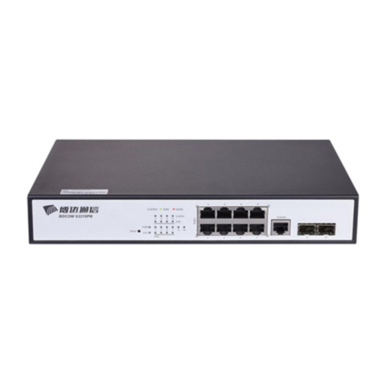
The document describes the characteristics and parameters of S2210PB and gives an overview of S2210PB. 1.1 Standard Configuration S2210PB switch has three parts: 8 IEEE802.3af/at 100M Ethernet TX ports, 2 gigabit Ethernet SFP ports and 1 Console port. See the following table: Table 1- 1 Attributes of necessary ports... - Page 4 2 SFP ports optical signals. Besides, S2210PB provides with a grounding column, a power socket, and a silent fan. Figure 1- 2 Back template of the S2210PB switch Table 1- 3 Parts at the rear template of the S2210PB switch Abbrev.
-
Page 5: Characteristic Parameters Of S2210Pb
S2210PB Hardware Installation Manual 1.2 Characteristic Parameters of S2210PB IEEE 802.1d Spanning Tree Protocol IEEE 802.1p Class of Service IEEE 802.1q tagged VLAN IEEE 802.3x Flow control Supported standard IEEE 802.3ad Link aggregation IEEE 802.3af Power via Media Dependent Interface Protocol IEEE 802.3at DTE Power Enhancements... -
Page 6: Rohs Description
S2210PB Hardware Installation Manual 1.3 ROHS Description - 4 -... -
Page 7: Chapter 2 Installation Preparation
Similar to other electronic products, the semiconductor chip easily gets damaged if you power on and off abruptly and frequently. To restart up the switch of S2210PB, you have to open the power on-off three or five seconds after the power is cut off. -
Page 8: Electrostatic Discharge Damage Prevention
2.3.1 Environment S2210PB switch adopts the wall-mounted installation mode. The switch has no fan, so an environment with good ventilation is needed for the heat cooling of the switch. For location planning and device locating, refer to section 2.3.2 “Location Configuration Prevention”. -
Page 9: Location Configuration Prevention
2.4 Installation Tools and Device The tools and devices to install the S2210PB switch are not provided by the S2210PB switch. You yourself need to prepare them. The following are the tools and devices needed for the typical installation of the S2210PB switch: ... -
Page 10: Chapter 3 Installing The S2210Pb Switch
Installing the Chassis on the Cabinet 3.2.1 Installing the Chassis on the Desk The S2210PB switch can be directly put on the smooth and safe desk. Note: Do not put things weighing 4.5 kg or over 4.5 kg on the top of the switch. -
Page 11: Connecting The Port
3.3.1 Connecting the Console Port The switch of S2210PB has a Console port. The rate of the console port is a value of 1200bps—115200bps. It has a standard RJ45 plug. After you connect the console port to the serial port of PC through a console cable, you can configure and monitor the switch of S2210PB by running a terminal emulation software, such as super Windows terminal. - Page 12 25-hole plug (DB25) and a 9-hole plug (DB9). The RJ45 plug is put into the socket of the console port on the S2210PB switch. DB25 or DB9 is applied according to the requirement of the terminal serial port. The inner line connection in the cable is shown in Figure 3-5.
-
Page 13: Connecting The Sfp Ports
3.3.2 Connecting the SFP Ports S2210PB provides 2 gigabit SFP optical ports. Each port corresponds to one indicator respectively, which is used for indicating the port Link/ACT state. When the indicator is always on, the link is normal; when it flickers, the data receives and forwards. To use the optical port, you need connect it to the SFP optical module, and then to other Ethernet terminal devices through an optical fiber. -
Page 14: Connecting 100M Ethernet Tx Ports
3.3.3 Connecting 100M Ethernet TX Ports The S2210PB switch has 8 10/100Base-TX ports. Each port has one indicator, which indicates the state of Link/ACT. If the indicator is always on, the port is linked up; if the indicator flickers, the data is transmitted on the port. The numbering order of the pins in the UTP port is the same as the console port. -
Page 15: Checkup After Installation
Check whether the connected power supply meets the power requirements of the switch. Check whether the grounding line of S2210PB is correctly connected. Check whether S2210PB is correctly connected to other terminal devices. ... -
Page 16: Chapter 4 S2210Pb Maintenance
Caution: Before opening the chassis, make sure that you have released the static you carried and then turn off the power on-off of S2210PB. Before operating any step in Appendix B, read the section “Safety Advice”. Before performing operations beside the power supply or on the chassis, turn off the power on-off and plug out the power cable. - Page 17 S2210PB Hardware Installation Manual Following the directions shown on the above-mentioned figure, install the cover and bottom of the frame box. Nail the bolt and screw it tightly with the screwdriver. Reinstall the switch on the DIN rail or on the desk.
-
Page 18: Chapter 5 Hardware Fault Analysis
9600 bps, eight data bits, no sum check bit, one stop bit and no traffic control. 5.2 LED Description The LED shows that the switch is running. The following table shows the LEDs of the S2210PB switch and their description: Abbrev. Name Remarks Power LED If the switch is powered, the indicator is on. - Page 19 S2210PB Hardware Installation Manual If the indicator is always on, it means that the connection is linked. LINK/ACT port indicators If the indicator is off, the port is not linked. If the indicator is always on, it means the indicator PoE works.
Need help?
Do you have a question about the S2210PB and is the answer not in the manual?
Questions and answers