Table of Contents
Advertisement
Advertisement
Table of Contents

Related Manuals for Bdcom S2928


Summary of Contents for Bdcom S2928
- Page 1 S2928 Hardware Installation Manual...
-
Page 2: Table Of Contents
2.3.3 Cabinet Configuration ....................7 2.3.4 Power Requirements ....................8 2.4 Installation Tools and Device....................8 Chapter 3 Installing the S2928 Switch ....................9 3.1 Installation Flow of S2928 ....................9 3.2 Installing the Machine Box of the Switch ................9 3.2.1 Installing the Machine Box on the Desk.............. - Page 3 Table of Contents 3.3.3 Connecting Gigabit Ethernet TX Port ..............12 3.3.4 Connecting Gigabit Ethernet SFP Port ..............14 3.4 Checking After Installation....................14 Chapter 4 Maintaining Switch......................15 4.1 Opening the Machine Box....................15 4.2 Closing the Machine Box ....................16 Chapter 5 Hardware Fault Analysis....................
-
Page 4: Chapter 1 S2928 Introduction
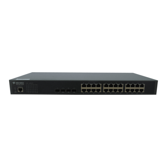
S2928. 1.1 Appearance Description for Standard Configuration The built-in ports of S2928 are: 20 gigabit-Ethernet TX port, 4 10G Ethernet SFP+ ports, 4 gigabit combo TX/ SFP+ ports, 1 Console port. See table 1-1. Table 1-1 Attributes of the built-in port... - Page 5 4 gigabit SFP ports optical signals Additionally, S2928 has a grounding column, a socket and a power on-off at its back. Figure 1-2 Back template of the S2928 switch Table 1-3 Parts at the back template of the S2928 switch Abbrev.
-
Page 6: S2928 Systematic Characteristic Parameters
S2928 Hardware Installation Manual 1.2 S2928 Systematic Characteristic Parameters IEEE 802.1d Spanning Tree Protocol IEEE 802.1s multiple spanning trees IEEE 802.1p Class of Service Supported IEEE 802.1q tagged VLAN standard Protoc IEEE 802.3x Flow control standa IEEE 802.3z asymmetric flow control IEEE 802.3ad Link aggregation... -
Page 7: Rohs Description
S2928 Hardware Installation Manual Net weight 2.5KG 1.3 ROHS Description - 4 -... -
Page 8: Chapter 2 Installation Preparation
Similar to other electronic products, the semiconductor chip easily gets damaged if you power on or off abruptly and frequently. To restart up the switch of S2928, you have to open the power on-off after the power is cut down for three to five seconds. -
Page 9: Safety Principles For Live Working
S2928 Hardware Installation Manual Pull out the AC power socket and close the direct-current power before operating on the machine box or working beside the power source. The final configuration of products must comply with relative national laws and regulations. -
Page 10: Electrostatic Discharge Damage Prevention
S2928 Hardware Installation Manual 2.2.4 Electrostatic Discharge Damage Prevention Electrostatic discharge may damage devices and circuits. Improper treatment may cause the switch to malfunction completely or discontinuously. Move or locate the devices according to the measures of electrostatic discharge prevention, ensuring the machine box connects the ground. Another measure is to wear the static-proof hand ring. -
Page 11: Power Requirements
2.4 Installation Tools and Device The tools and devices to install the S2928 switch are not provided by the S2928 switch. You yourself need to prepare them. The following are the tools and devices needed for... -
Page 12: Chapter 3 Installing The S2928 Switch
S2928 Hardware Installation Manual Chapter 3 Installing the S2928 Switch Caution: Only professionals are allowed to install or replace the devices. 3.1 Installation Flow of S2928 3.2 Installing the Machine Box of the Switch The installation of the machine box has two modes:... -
Page 13: Installing The Machine Box On The Desk
RJ45 plug. After you connect the console port to the serial port of PC through a console cable, you can configure and monitor the switch of S2928 by running the terminal emulation software, such as super Windows terminal. The cable is provided according to the host. - Page 14 The other end of the console port is 9-hole plug. RJ45 connects to DB9 in the console port shown as below. Figure 3-4 Cable connection at the console port Figure 3-5 Connecting the console port of S2928 and computer - 11 -...
-
Page 15: Connecting Gigabit Ethernet Sfp+ Port
No connect Note: The console port of S2928 does not support traffic control. Therefore, you must set the option data traffic control to none when you configure the switch with the super terminal. Otherwise, the single-pass problem will arise on the super terminal. - Page 16 S2928 support MDI/MDIX self-identification of the cable, S2928 can adopt five types of direct-through/cross network cables when it connects other Ethernet terminals. Figure 3-7 Connecting the 1000Base-TX port and other Ethernet terminals Table 3-2 Pins of gigabit RJ45 Pin Name...
-
Page 17: Connecting Gigabit Ethernet Sfp Port
S2928 Hardware Installation Manual 3.3.4 Connecting Gigabit Ethernet SFP Port S2928 provides 4 gigabit SFP ports. The four ports correspond to indicators G21-G24. The ports can connect other Ethernet terminal devices through the SFP optical modules and the direct-through or cross network cable. -
Page 18: Chapter 4 Maintaining Switch
S2928 Hardware Installation Manual Chapter 4 Maintaining Switch Caution: Before opening the machine box, make sure that you have released the static you carried and then turn off the power on-off of the switch. Before operating any step in Appendix B, read the section “Safety Advice”. -
Page 19: Closing The Machine Box
S2928 Hardware Installation Manual Note: After taking off the cover, put it horizontally and avoid it to be crushed or collided. Otherwise, the machine box is hard to install. 4.2 Closing the Machine Box The section mainly describes how to put the cover and close the machine box. Do as... -
Page 20: Chapter 5 Hardware Fault Analysis
9600 bps, eight data bits, no sum check bit, one stop bit and no traffic control. 5.2 Indicator Description The following table shows the indicators of the S2928 switch and their description: Abbrev. Name... - Page 21 S2928 Hardware Installation Manual When the switch is powered on, Power indicator the indicator is on. When the indicator is always on, the system is being started up. System indicator When the indicator flickers, the system works well. If the indicator is always on, it means that the connection is linked.
Need help?
Do you have a question about the S2928 and is the answer not in the manual?
Questions and answers