Table of Contents
Advertisement
Advertisement
Table of Contents

Related Manuals for Bdcom S3740


Summary of Contents for Bdcom S3740
- Page 1 S3740 Hardware Installation Manual...
-
Page 2: Table Of Contents
Table of Contents ..........................I Chapter 1 S3740 Introduction ......................1 1.1 Appearance Description for Standard Configuration ............1 1.2 S3740 Systematic Characteristic Parameters ..............2 1.3 ROHS Description ........................ 4 Chapter 2 Installation Preparation ..................... 5 2.1 Caution of Usage ......................... 5 2.2 Safety Advice ........................ - Page 3 Table of Contents 3.4 Checking After Installation ....................13 Chapter 4 Maintaining Switch ......................15 4.1 Opening the Machine Box ....................15 4.2 Closing the Machine Box ....................16 Chapter 5 Hardware Fault Analysis ....................17 5.1 Fault Separation ......................... 17 5.1.1 Faults Relative with Power and Cooling System .............
-
Page 4: Chapter 1 S3740 Introduction
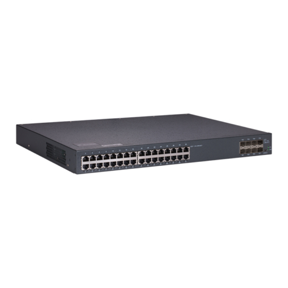
S3740 1.1 Appearance Description for Standard Configuration The built-in ports of S3740 are: 32 gigabit Ethernet RJ45 ports, 8 10G Ethernet SFP+ ports and 1 Console port. See table 1-1. Table 1-1 Attributes of the built-in port Port... -
Page 5: S3740 Systematic Characteristic Parameters
If the switch is powered on, the indicator Power indicator is on. Additionally, S3740 has a grounding column and a power socket at its back. Figure 1-2 Back template of the S3740 switch Table 1-3 Parts at the back template of the S3740 switch Abbrev. - Page 6 S3740 Hardware Installation Manual 32 10/100/1000BASE-T ports Standard 8 10G Ethernet SFP+ ports configuration 1 Console port Dimensions 442.50 ×315 ×44 (W×D×H) Operating 0℃~40℃;10%~85% non-condensation temperature/ humidity Storage temperature/ -40℃~80℃; 5%~95% non-condensation Hardware humidity characteristics Input voltage:AC100~240V, Input frequency: 47~63Hz Power characteristics Input current: 1.5A (MAX)
-
Page 7: Rohs Description
S3740 Hardware Installation Manual 1.3 ROHS Description - 4 -... -
Page 8: Chapter 2 Installation Preparation
Similar to other electronic products, the semiconductor chip easily gets damaged if you power on or off abruptly and frequently. To restart up the switch of S3740, you have to open the power on-off after the power is cut down for three to five seconds. -
Page 9: Safety Principles For Live Working
S3740 Hardware Installation Manual Only professionals are allowed to install or replace the switch. Pull out the AC power socket and close the direct-current power before operating on the machine box or working beside the power source. ... -
Page 10: Electrostatic Discharge Damage Prevention
S3740 Hardware Installation Manual 2.2.4 Electrostatic Discharge Damage Prevention Electrostatic discharge may damage devices and circuits. Improper treatment may cause the switch to malfunction completely or discontinuously. Move or locate the devices according to the measures of electrostatic discharge prevention, ensuring the machine box connects the ground. Another measure is to wear the static-proof hand ring. -
Page 11: Power Requirements
2.4 Installation Tools and Device The tools and devices to install the S3740 switch are not provided by the S3740 switch. You yourself need to prepare them. The following are the tools and devices needed for the typical installation of the S3740 switch: ... -
Page 12: Chapter 3 Installing S3740 Switch
S3740 Hardware Installation Manual Chapter 3 Installing S3740 Switch Caution: Only professionals are allowed to install or replace the devices. 3.1 Installation Flow of S3740 3.2 Installing the Machine Box of the Switch The installation of the machine box has two modes: ... -
Page 13: Installing The Machine Box On The Desk
USB plug. After you connect the console port to the serial port of PC through a console cable, you can configure and monitor the switch of S3740 by running a terminal emulation software, such as super Windows terminal. The cable is provided according to the... - Page 14 One end of the cable is a mini USB plug and the other end is a 9-hole plug (DB9). See the following figure: Figure 3-4 Cable connection at the console port Figure 3-5 Connecting the console port of S3740 and computer Table 3-1 Pins of the console port Name...
-
Page 15: Connecting 10G Ethernet Sfp+ Ports
Output Note: The console port of S3740 does not support traffic control. Therefore, you must set the option data traffic control to none when you configure the switch with the super terminal. Otherwise, the single-pass problem will arise on the super terminal. -
Page 16: Checking After Installation
S3740 Hardware Installation Manual Figure 3-7 Connecting the 1000Base-TX port and other Ethernet terminals Table 3-2 Pins of gigabit RJ45 Pin Name Remark Sending/receiving the normal phase of data 0 TP0+ Sending/receiving the paraphase of the data 0 TP0- Sending/receiving the normal phase of data 1... - Page 17 S3740 Hardware Installation Manual Check whether the connected power meets the power requirements of the switch. - 14 -...
-
Page 18: Chapter 4 Maintaining Switch
S3740 Hardware Installation Manual Chapter 4 Maintaining Switch Caution: (1) Before opening the machine box, make sure that you have released the static you carried and then turn off the power on-off of the switch. Before operating any step in Appendix B, read the section “Safety Advice”. -
Page 19: Closing The Machine Box
S3740 Hardware Installation Manual Caution: The switch shown in the above figure does not represent the material S3740. (5) When the cover is opened, put it aside. The mainboard of the system appears. Note: After taking off the cover, put it horizontally and avoid it to be crushed or collided. -
Page 20: Chapter 5 Hardware Fault Analysis
9600 bps, eight data bits, no sum check bit, one stop bit and no traffic control. 5.2 Indicator Description The LED indicator shows that the switch is running. The following table shows the indicators of the S3740 switch and their description: - 17 -... - Page 21 S3740 Hardware Installation Manual Abbrev. Name Description When the switch is powered on, the Power indicator indicator is on. When the indicator is always on, the system is being started up. System indicator When indicator flickers, system works well. When the indicator is always on, the port is linked.
Need help?
Do you have a question about the S3740 and is the answer not in the manual?
Questions and answers