Table of Contents
Advertisement
Quick Links
Advertisement
Table of Contents

Subscribe to Our Youtube Channel
Related Manuals for Michell Instruments Optidew


Summary of Contents for Michell Instruments Optidew
- Page 1 Optidew Chilled Mirror Hygrometer User's Manual 97551 Issue 4.1 October 2019...
- Page 2 Please fill out the form(s) below for each instrument that has been purchased. Use this information when contacting Michell Instruments for service purposes. Analyzer Code Serial Number Invoice Date Location of Instrument Tag Number Analyzer Code Serial Number Invoice Date...
- Page 3 © Michell Instruments 2019 This document is the property of Michell Instruments Ltd and may not be copied or otherwise reproduced, communicated in any way to third parties, nor stored in any Data Processing System without the express written authorization of Michell Instruments Ltd.
-
Page 4: Table Of Contents
Calibration (Factory Validation) ..................ix Repair and Maintenance ....................ix Abbreviations ....................... x 1. INTRODUCTION ..................... 1 1.1. Optidew Series ......................1 1.2. Optidew Sensor ....................... 2 1.3. Minimum Measurable Dew Points ................3 1.4. Remote Temperature Probes ..................4 2. - Page 5 3.2.6. Clock ....................... 28 3.2.7. Inputs ......................29 3.2.8. Comms Screen ....................30 3.2.9. Network Settings ....................30 3.3. Optidew 501 Transmitter without display ..............31 3.3.1. Optics Calibration ..................... 31 4. OPERATION ......................32 4.1. Operating Cycle ..................... 32 4.2.
- Page 6 Figure 4 Labatory/High Temperature Probe ................4 Figure 5 Optidew 501 wall mounting points ................6 Figure 6 Optidew 501 with Touch Screen display or DCC control button ........7 Figure 7 Optidew 501 bottom panel ..................7 Figure 8 Optidew 401 front and side panels ................8 Figure 9 Optidew 401 rear panel ..................
- Page 7 Optidew User’s Manual Figure 20 Alarm Screen ....................26 Figure 21 Display Screen ....................27 Figure 22 Clock Screen ..................... 28 Figure 23 Inputs Screen ....................29 Figure 24 Comms Screen ....................30 Figure 25 Network Settings Screen ..................30 Figure 26 Typical Operating Cycle..................
-
Page 8: Safety
Optidew User’s Manual Safety The instrument is designed to be completely safe when installed and operated correctly in accordance with the information provided in this manual. This manual contains all the required information to install, operate and maintain this product. -
Page 9: Electrical Safety
Michell Instruments can provide a fully traceable factory calibration service for the instrument and it is recommended that this is considered at intervals of every year of the analyzer's life. -
Page 10: Abbreviations
Optidew User’s Manual Abbreviations The following abbreviations are used in this manual: ampere alternating current pressure unit (atmosphere) bara pressure unit (=100 kP or 0.987 atm) absolute barg pressure unit (=100 kP or 0.987 atm) gauge °C degrees Celsius °F... -
Page 11: Introduction
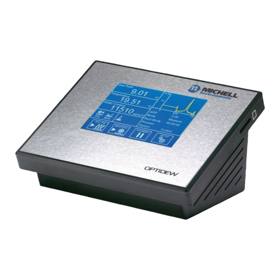
IP65. Note that the Ethernet and SD card options are not available in combination with the weatherproof version. The Optidew 401 is designed to be easy to handle and transport and is ideal for laboratory or service use. It has a 5.7” touch screen LCD fitted as standard. -
Page 12: Optidew Sensor
Optidew User’s Manual 1.2. Optidew Sensor The new Optidew sensor is available with either a single or dual stage thermoelectric cooler and with a choice of sensor head materials making it suitable for use in air/inert gases or in corrosive environments. -
Page 13: Minimum Measurable Dew Points
Optidew User’s Manual 1.3. Minimum Measurable Dew Points The minimum dew point that can be measured is determined by the sensor temperature, and whether the sensor can be maintained at that temperature. The following chart assumes operation in a climatic chamber, where the air speed is sufficient to remove any excess heat generated by the sensor. -
Page 14: Remote Temperature Probes
Optidew User’s Manual 1.4. Remote Temperature Probes Two versions of temperature probe are available for the Optidew, a general purpose probe rated to +90°C, and a laboratory/high temperature probe rated to +120°C. General Purpose Probe Figure 3 General Purpose Probe This 75mm probe is supplied when any of the 'standard' sensor cable options are selected. -
Page 15: Installation
• Mains Cable 2.2. Mounting Optidew 401 The Optidew 401 is designed to be placed on a bench or table during operation. Alternatively, it can be used inside the optional Transport Case. Optidew 501 The Optidew can be wall mounted using the four mounting points on each corner (see figure 2 for mounting point dimensions). -
Page 16: Figure 5 Optidew 501 Wall Mounting Points
Optidew User’s Manual Wall Mounting Points 240 (9,4) 26 (10,2) Figure 5 Optidew 501 wall mounting points 97551 Issue 4.1, October 2019... -
Page 17: Instrument Connections
Optidew User’s Manual 2.3. Instrument Connections 2.3.1. Optidew 501 Figure 6 Optidew 501 with Touch Screen display or DCC control button Number Description DCC Control/ Status indicator Sensor Cable connector Temperature probe cable connector Pressure transmitter cable connector Alarm contacts connector... -
Page 18: Optidew 401
Optidew User’s Manual 2.3.2. Optidew 401 Figure 8 Optidew 401 front and side panels Number Description Power Connector Power Switch SD card slot Alarm contacts connector RS485 and analog output connector USB port Ethernet port (optional) Sensor Cable connector Temperature probe cable connector... -
Page 19: Electrical Connections
Replacement power cables are available - contact your Michell representative. Optidew 401 The Optidew 401 is supplied with a 2m IEC cable. The IEC socket is on the left hand side of the instrument. There is an ON/OFF switch on the front panel. Only use an appropriately rated detachable mains supply cord. -
Page 20: Analog And Digital Communications
RS485 Data A Ground The Optidew provides Modbus RTU over RS485 or USB (Bench Top only). An Ethernet module is optionally available for both instruments and provides Modbus TCP communication. The Modbus register map can be found in Appendix B. -
Page 21: Figure 12 Analog Output Connector
Optidew User’s Manual 2.4.2.2. Current Outputs Figure 12 Analog output connector Left to right, the last four pins on this connector are used for mA outputs. See section 3.2 for information on configuring the analog outputs Pin Label Description Channel 2 Current Output... -
Page 22: Figure 13 Relay Contact Connector
Optidew User’s Manual 2.4.2.3. Relay Contacts There are two sets of relay contacts available via the output connector: Process Alarm (Relay 1) This relay changes state to indicate that the process variable has exceeded the alarm set point value. See section 3.2 for details on how to configure the process alarm trip criteria. This alarm can also be used to give an early indication that the Optics require cleaning. -
Page 23: Sensor Installation
Optidew User’s Manual 2.5. Sensor Installation The dew-point sensor contains the optical system and the chilled mirror. It is fitted with a 12-pin M12 connector to allow easy and secure connection to the instrument using the supplied sensor cable. The available options for sensor installation are: •... -
Page 24: Environmental Chamber Or Glovebox Sensor Mounting
Be aware that when depressing the mirror temperature by more than 40°C, the Optidew dew- point sensor will generate a small amount of heat in the surrounding area. Try to situate the temperature probe upstream of the dew-point sensor and at least 150mm away. -
Page 25: Using Temperature Probes With A Chamber Port Adapter
Pressure transmitters are available for the Optidew in several ranges. Any 4-20mA pressure transmitter can be wired into the Optidew control unit via the 4-pin M12 connector. Michell can supply a pressure transmitter with the Optidew, which is installed via a 1/8” NPT male thread. -
Page 26: User Interface
LED indicator. The application software gives the user access to all functionality available through the local user interface. The Optidew offers three interfaces to connect to a PC or network: • RS485 •... -
Page 27: Main Screen
Optidew User’s Manual 3.1.2. Main Screen Figure 16 Main Screen layout Name Description Customizable Display measured and calculated parameters. See section 3.1.3 Readouts for additional information Displays both thermo-electric cooler (TEC) drive and optical Sensor Status signal condition. Also indicates whether TEC is 1 or 2 stage. See Display section 3.1.7 for additional information... -
Page 28: Customizable Readouts
Optidew User’s Manual 3.1.3. Customizable Readouts The three readouts on the Main Screen can be configured by the User to show any of the following parameters: • Dew Point • Temperature • Pressure • % Relative Humidity • g/m3 • g/kg •... -
Page 29: Menu Structure
Optidew User’s Manual 3.1.5. Menu Structure Michell Instruments... -
Page 30: Operational Status Display
Optidew User’s Manual 3.1.6. Operational Status Display Shows total change in measured dew point over the ΔDP time base of the trend graph Mode Shows current operation mode: Next Mode Measure, Standby, DCC, Max Cool, Data Hold Status of process alarms... -
Page 31: Sensor Status Display
PC Application Software to enter the sensor configuration code found on the calibration certificate. Refer to section 6.2 Exchanging Sensors. When shown, the Optidew is currently Logging logging data to SD. See section 4.4.6 for further information. -
Page 32: Setup Menus
Optidew User’s Manual 3.2. Setup Menus 3.2.1. DCC Figure 17 DCC Menu DCC heating temperature can either be relative to last measured dew point or an absolute temperature. Actual temperature or Δ is Type defined by ‘Setpoint’. Available input: Relative, Absolute... - Page 33 Optidew User’s Manual Turns frost assurance on or off. See section 4.4.3 for further FAST information Available input: On, Off Passing this mirror temperature will trigger the frost assurance FAST SetP function without a DCC Available input: -28 to -2°C...
-
Page 34: Logging
Optidew User’s Manual 3.2.2. Logging Figure 18 Logging Screen Changes the interval at which data is recorded Interval Input format: mm:ss – Limits: 00:05 to 10:00 Indicates status of inserted SD card: No SD Card inserted Ready to log Initialising card... -
Page 35: Outputs
Optidew User’s Manual 3.2.3. Outputs Figure 19 Outputs Screen Output selector Selects the output to be adjusted arrows Determines the mA output range Output Type Available input: 0-20mA, 4-20mA Assigns the chosen calculated or measured parameter to this output channel... -
Page 36: Alarm
Optidew User’s Manual 3.2.4. Alarm Figure 20 Alarm Screen Sets the trip criteria for the process alarm Type Available input: Over, Under, In. Band, Out. Band, Off Sets the parameter associated with the process alarm Parameter Available input: DP, Temperature, Pressure, %RH, wvp, g/m... -
Page 37: Display
Optidew User’s Manual 3.2.5. Display Figure 21 Display Screen Changes the number of decimal places for all displayed parameters Resolution Available input: 1 DP, 2 DP Measurement unit for temperature values Temperature Unit Available input: °C, °F Measurement unit for pressure values... -
Page 38: Clock
Optidew User’s Manual 3.2.6. Clock Figure 22 Clock Screen Date Current date Time Current time 97551 Issue 4.1, October 2019... -
Page 39: Inputs
Optidew User’s Manual 3.2.7. Inputs Figure 23 Inputs Screen Changes between pressure input from external 4-20mA transmitter Source (Pressure or a fixed value Input) Available input: Fixed, External Measurement unit for pressure inputs Pressure Unit Available input: kPa, psig, psia, barg, bara Value (If ‘Fixed’... -
Page 40: Comms Screen
Optidew User’s Manual 3.2.8. Comms Screen Figure 24 Comms Screen Modbus Address Sets the Modbus slave address for this Optidew Setup Access the TCP/IP Network Settings page 3.2.9. Network Settings Figure 25 Network Settings Screen IP Address IP address of the instrument (default 10.0.50.100) Subnet Mask Determines network subnet address (default 255.255.255.0) -
Page 41: Optidew 501 Transmitter Without Display
Optidew User’s Manual 3.3. Optidew 501 Transmitter without display The Optidew 501 can also be ordered as a blind transmitter without display. This variant instead comes with a single multi-function button with integrated colored LED status indicator. The indicator changes color and pulse rate depending on the instrument status. -
Page 42: Operation
Optidew User’s Manual 4. OPERATION 4.1. Operating Cycle Figure 26 Typical Operating Cycle At initial switch-on, the instrument enters a DCC cycle for 2 minutes. During this time the mirror is heated above the prevailing dew point to ensure that all condensate is driven off the surface of the mirror. -
Page 43: Operating Guide
4.2. Operating Guide 4.2.1. Description Once the Optidew has been powered on and has carried out its’ initial DCC, it will attempt to find the dew point. In order to measure the dew point a Chilled Mirror hygrometer must control a thin film of condensed water or ice on the mirror. -
Page 44: Figure 27 Room Measurement Example
If this is the case, then a guard fitted over the sensor can mitigate the effects of excessive gas speed by dissipating the sample throughout it’s surface area. An appropriate guard can be purchased from Michell Instruments, contact your local representative. 97551 Issue 4.1, October 2019... -
Page 45: Figure 28 Mirror Contaminaton Warning Symbol
You can then either enter this pressure into the Optidew via the ‘Inputs’ screen (see section 3.2) or connect a pressure sensor directly to the point of measurement (see section 2.6). -
Page 46: Good Measurement Practice
Optidew User’s Manual 4.3. Good Measurement Practice 4.3.1. Sampling Hints Ensuring reliable and accurate moisture measurements requires the correct sampling techniques, and a basic understanding of how water vapour behaves. This section aims to explain the common mistakes and how to avoid them. -
Page 47: Figure 30 Condensation In Sample Tubing
Optidew User’s Manual Take into consideration the gas you are measuring, and then choose materials appropriate to the results you need. The effects of diffusion or moisture trapped in materials are more significant when measuring very dry gases than when measuring a sample with a high level of humidity. - Page 48 Optidew User’s Manual Theoretically flow rate has no direct effect on the measured moisture content, but in practice it can have unanticipated effects on response speed and accuracy. An inadequate flow rate may: • Accentuate adsorption and desorption effects on the gas passing through the sampling system.
-
Page 49: First Time Operation
Optidew User’s Manual protection from liquid droplets and can even stop flow to the analyser completely when a large slug of liquid is encountered, saving the sensor from potentially irreparable damage. 4.3.2. First Time Operation Before using the instrument, please read through the Installation, Operation and Maintenance sections of this manual. -
Page 50: Maxcool Function
There are two modes of FAST operation, enabling and disabling FAST acts on both modes: Following DCC: the Optidew makes an initial dew point measurement. If the initial measurement is between -3°C and -30°C, then the mirror is driven down to below -35°C to ensure the formation of ice on the mirror surface. -
Page 51: Standby Mode
These additional readings can either come from a sensor connected to the Optidew, or from a fixed (manual) input. See section 3.2 for details on external inputs. -
Page 52: Data Logging
Section 3.2. 5. WARNINGS AND FAULTS The Optidew contains a comprehensive self-diagnosis system to alert the user whenever there is an issue which could affect the measurement. These alerts are divided into two categories: Warnings – A problem which is not currently affecting the measurement but requires attention. - Page 53 Optidew User’s Manual Possible Fault Codes Name Description Mirror Overheat Mirror Temperature above 130°C Optics Fault (Search Fail) Unable to establish clean mirror condition Optics Fault (< Min Limit) Signal below allowable limit Optics Fault (> Max Limit) Signal above allowable limit...
-
Page 54: Maintenance
The Optidew will notify the user on the state of mirror contamination. The instrument will initially give a warning in the sensor status display (or as a Magenta/flashing Magenta indication on the transmitter version) when contamination is detected but will continue to operate. -
Page 55: Exchanging Sensors
Optidew User’s Manual 6.2. Exchanging Sensors It is recommended to keep the dew-point sensor with the control unit that it was originally ordered with. However, if it is necessary to replace the sensor or exchange it for a spare, there are two steps which need to be taken. - Page 56 Optidew User’s Manual Теchnical Specifications 97551 Issue 4.1, October 2019...
-
Page 57: Technical Specifications
Optidew User’s Manual Technical Specifications Performance Dew Point ±0.15°C Measurement Accuracy Repeatability ±0.05°C Sensitivity ±0.01°C Response Stable measurement at +10°C dp within 1 minute Dew-Point Sensor Sensor Single Stage Dual Stage Harsh Environment Dew Point Range (°C) -25 to +90... - Page 58 Optidew User’s Manual Control Unit Resolution 1 or 2 decimal places selectable °Cdp or °Fdp Relative humidity - % Absolute humidity - g/m , ppm %Vol Mixing Ratio - g/kg Measurement Units Wet Bulb Temperature (Twb) - °C, °F Water Vapour Pressure (wvp) - Pa Ambient Temperature - °C, °F...
- Page 59 Optidew User’s Manual Modbus Register Map Michell Instruments...
-
Page 60: Modbus Register Map
Optidew User’s Manual Modbus Register Map All the data values relating to the Optidew are stored in 16-bit wide holding registers. Registers can contain either measured or calculated values (dew-point, temperature, relative humidity etc.), or configuration data (analog output or alarm settings). - Page 61 Optidew User’s Manual Register Address Data Access Description Comment Type Instrument Information uint16 Instrument Modbus Address 0000 uint32 Instrument Serial MS 0002 Instrument Serial LS 0003 uint16 Instrument Firmware Version 0004 uint16 Register Map Version 0005 Measured and Calculated Values...
- Page 62 Optidew User’s Manual float Water Vapour Pressure MS Units = Pascal 0018 Water Vapour Pressure LS 0019 uint16 Temperature Unit Set using register 100 001E 0 = °C 1 = °F uint16 Pressure Unit Set using register 101 001F 0=psig...
- Page 63 Optidew User’s Manual bit0=Ambient Pt100 Open bit1=Ambient Pt100 Low bit2=Ambient Pt100 High bit3=Mirror Pt100 Open bit4=Mirror Pt100 Low bit5=Mirror Pt100 High bit6=Loop Open (Pressure Tx) bit7=Loop Alarm (Pressure Tx) bit8=Loop Fail (Pressure Tx) bit9=Contaminated uint16 Alarms Status 0028 bit0=System bit1=Process...
- Page 64 Optidew User’s Manual swvp calculated over %RH - Force Over Water water in %RH boolean 0068 SWVP (WMO standard) calculation as per WMO standard Use wet basis 0069 boolean ppm(vol) Wet Basis calculation method Atmospheric pressure float Atmospheric Pressure MS...
- Page 65 Optidew User’s Manual 0=External 1=Manual float Manual Temperature MS 007D Manual Temperature LS 007E Instrument Configuration uint16 DCC Setpoint Mode 007F 0=Absolute 1=Relative int16 DCC Temperature Setpoint (Degrees * 100) 0080 uint16 DCC Interval Mode 0081 0=Auto (Recommended) 1=Manual uint16...
- Page 66 Optidew User’s Manual uint16 Displayed Parameter 1 0093 0=Dew/Frost point 1=Temperature 2=Pressure 3=Relative Humidity 4=ppm(vol) 5=ppm(wt.) 6=Mixing Ratio 7=Absolute Humidity 8=Wet bulb 9=WVP uint16 Displayed Parameter 2 0094 uint16 Displayed Parameter 3 0095 boolean Enable Display Hold 0096 Analog Output Settings...
- Page 67 Optidew User’s Manual 2=Process Only 3=Both uint16 Analogue 2 Alarm Type 00A8 uint16 Process Alarm Parameter 00AB 0=Dew/Frost point 1=Temperature 2=Pressure 3=Relative Humidity 4=ppm(vol) 5=ppm(wt.) 6=Mixing Ratio 7=Absolute Humidity 8=Wet bulb 9=WVP uint16 Process Alarm Type 00AC Ethernet Settings 00C9...
-
Page 68: Further Reading
Optidew User’s Manual Further Reading http://www.simplymodbus.ca/FAQ.htm is an excellent resource covering the basics of the Modbus protocol. Full descriptions of the function codes (FC03/FC06/FC16) can be found in the sidebar. https://www.scadacore.com/tools/program ming-calculators/online-hex-converter/ is an excellent resource for determining register types/byte order issues in raw received Modbus data. - Page 69 Optidew User’s Manual Dimensional Drawings Michell Instruments...
-
Page 70: Dimensional Drawings
Optidew User’s Manual Dimensional Drawings Optidew 401 Bench Top analyzer 97551 Issue 4.1, October 2019... - Page 71 Optidew User’s Manual Optidew 501 Wall Mount Analyzer – IP54 Michell Instruments...
- Page 72 Optidew User’s Manual Optidew 501 Wall Mount Transmitter – IP65 97551 Issue 4.1, October 2019...
- Page 73 Optidew User’s Manual Single Stage Dew-Point Sensor Michell Instruments...
- Page 74 Optidew User’s Manual Dual Stage Dew-Point Sensor 97551 Issue 4.1, October 2019...
- Page 75 Optidew User’s Manual Sample Block Michell Instruments...
- Page 76 Optidew User’s Manual Standard Temperature Probe *Weld burr may extend from 1mm from colar to towards tip of probe. Probe and connector rated 90°C. High Temperature Probe Maximum temperature measurement 120°C. Connector rated 120°C. Probe and cable rated 250°C. 97551 Issue 4.1, October 2019...
- Page 77 Optidew User’s Manual Quality, Recycling & Warranty Information Michell Instruments...
-
Page 78: Quality, Recycling, Compliance & Warranty Information
Optidew User’s Manual Quality, Recycling, Compliance & Warranty Information Michell Instruments is dedicated to complying to all relevant legislation and directives. Full information can be found on our website at: www.michell.com/compliance This page contains information on the following directives: • ATEX Directive •... - Page 79 Optidew User’s Manual Return Document & Decontamination Declaration Michell Instruments...
-
Page 80: Return Document& Decontamination Declaration
Optidew User’s Manual Return Document& Decontamination Declaration 97551 Issue 4.1, October 2019... - Page 81 Optidew User’s Manual Notes: Michell Instruments...
- Page 82 http://www.michell.com...
Need help?
Do you have a question about the Optidew and is the answer not in the manual?
Questions and answers