Table of Contents
Advertisement
Quick Links
Advertisement
Table of Contents

Related Manuals for Michell Instruments Easidew Online


Summary of Contents for Michell Instruments Easidew Online
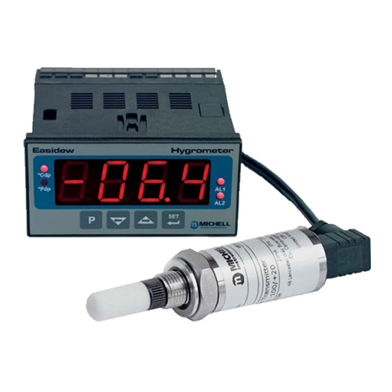
- Page 1 Easidew Online Dew-Point Hygrometer User’s Manual 97094 Issue 18.5 March 2016...
- Page 2 Please fi ll out the form(s) below for each instrument that has been purchased. Use this information when contacting Michell Instruments for service purposes. Instrument Code Serial Number Invoice Date Location of Instrument Tag No Instrument Code Serial Number Invoice Date...
- Page 3 © 2016 Michell Instruments This document is the property of Michell Instruments Ltd. and may not be copied or otherwise reproduced, communicated in any way to third parties, nor stored in any Data Processing System without the express written authorization of Michell Instruments Ltd.
-
Page 4: Table Of Contents
Unpacking the Easidew Transmitter ..............4 2.1.2 Unpacking the Monitor .................. 4 2.1.3 Accessories Pack ................... 5 Easidew Online Components ................5 Easidew Transmitter ................... 6 Monitor ......................7 Monitor Panel Layout ..................7 Function Keys ..................... 9 Mounting the Monitor ..................10 Electrical Connections .................. - Page 5 Maintenance and Calibration ................42 4.2.1 Clean Monitor .................... 42 Fault Conditions ....................43 Figures Figure 1 Easidew Online Monitor and Transmitter ............1 Figure 2 Unpacking Method ..................3 Figure 3 Transmitter Unpacking Method ..............4 Figure 4 Monitor Unpacking Method ................4 Figure 5 Accessories Pack ..................5...
- Page 6 Easidew Online User’s Manual Tables Table 1 Monitor Front Panel Controls and Indicators ..........8 Table 2 Function Keys ....................9 Table 3 Summary of Electrical Connections ............. 24 Appendices Appendix A Technical Specifi cations ................45 Dimensions ................. 47 Appendix B RS232 Data Communications Port Connections (Optional) ......
-
Page 7: Safety
The instrument should be returned to the manufacturer, Michell Instruments Ltd., or one of their accredited service agents for re-calibration. Safety Conformity This product meets the essential protection requirements of the relevant EU and US directives. -
Page 8: Abbreviations
Easidew Online User’s Manual Abbreviations The following abbreviations are used in this manual: alternating current pressure unit (atmosphere) barg pressure unit (=100 kP or 0.987 atm) gauge bara bar absolute °C degrees Celsius °F degrees Fahrenheit direct current foot (feet) -
Page 9: Introduction
Easidew Online User’s Manual INTRODUCTION INTRODUCTION The Easidew Online dew-point hygrometer is an instrument designed for the continuous online measurement of moisture content in non-corrosive gases, over an operational range of -100 to +20ºCdp (-148 to +68ºFdp). The system comprises a programmable monitor confi gured to accept a 4-20 mA current loop signal from an impedance-type dew-point temperature measurement transmitter. -
Page 10: Features
Easidew Online User’s Manual INTRODUCTION Features The Easidew Online Hygrometer is simple to use and install, and can be confi gured to meet specifi c needs. • 5/8”- 18 UNF process connections • Dew-point or ppm moisture content • IP66 (NEMA 4) Sensor and IP65 (NEMA 12) Monitor (front panel only) •... -
Page 11: Installation
Easidew Online User’s Manual INSTALLATION INSTALLATION It is essential that the connection of electrical and gas supplies to this instrument be undertaken by competent personnel. Unpacking the Instrument The Easidew instruments and accessories are packed into a box and the method of... -
Page 12: Unpacking The Easidew Transmitter
Easidew Online User’s Manual INSTALLATION 2.1.1 Unpacking the Easidew Transmitter NOTE: For environmental and operating conditions refer to Appendix A. Unpack the dew-point transmitter box as follows : Figure 3 Transmitter Unpacking Method Unscrew the cap (1) from the packing tube (6). Remove the foam block (2). -
Page 13: Accessories Pack
Remove the screwdriver (1), the two leads (2) and (3) and the sample block (4) from the bag. Easidew Online Components On delivery please check that all the following standard components are present in the packing box. Report any shortages to Michell Instruments, immediately. Easidew Online Components Figure 6 Monitor clamps (2 off) -
Page 14: Easidew Transmitter
Easidew Online User’s Manual INSTALLATION Easidew Transmitter NOTE: The transmitter’s sensing element is shown for illustration purposes only. Please keep the HDPE or SS guard fi tted at all times, if possible. Sensing Element Process Connection Hexagonal Nut Transmitter Label... -
Page 15: Monitor
Easidew Online User’s Manual INSTALLATION Monitor The controls and indicators associated with the Easidew Online are located on the front panel of the monitor. Connections to the Easidew dew-point transmitter, the RS232 communications port and the external power supply are all made to the rear panel of the monitor. -
Page 16: Table 1 Monitor Front Panel Controls And Indicators
Easidew Online User’s Manual INSTALLATION Item Description °Fdp When illuminated, this LED indicates that the displayed dew-point reading is in degrees Fahrenheit. Note: If neither the °Fdp or °Cdp LED is lit, ppm is selected. °Cdp When illuminated, this LED indicates that the displayed dew-point reading is in degrees Celsius. -
Page 17: Function Keys
Easidew Online User’s Manual INSTALLATION Function Keys The function key panel is shown in Figure 8 . Table 2 describes the operation of the keys. Item Description P (Program) key This key is used to access the programming menus and to select sub-menus within the list. -
Page 18: Mounting The Monitor
Easidew Online User’s Manual INSTALLATION Mounting the Monitor The monitor is designed for panel mounting and requires a panel cut-out of 46 x 92mm (1.8 x 3.6”). The recommended panel thickness is 2 to 5mm (0.08 to 0.2”). To mount the unit, proceed as follows (refer to Figure 9): Pass the monitor (1) through the front of the panel (2). -
Page 19: Electrical Connections
Easidew Online User’s Manual INSTALLATION Electrical Connections Electrical connections to the Easidew Online system are as follows: • AC power supply, 100 to 240 V AC (-15%, +10%), 50/60 Hz, 6 VA. A low voltage (24 V DC) option is also available. -
Page 20: Ac Power Supply Input
Easidew Online User’s Manual INSTALLATION 2.8.1 AC Power Supply Input It is essential that the connection of electrical supplies to this instrument be undertaken by competent personnel. Connect the AC power supply to the monitor as shown in Figure 10 . Refer also to Table 3 which gives a summary of all the connections to the rear panel of the monitor. -
Page 21: Dc Power Supply Input (Optional)
Easidew Online User’s Manual INSTALLATION 2.8.2 DC Power Supply Input (Optional) Connect the DC power supply to the monitor as shown in Figure 11 . Refer also to Table 3 which gives a summary of all the connections to the rear panel of the monitor. -
Page 22: Preliminary System Test
Easidew Online User’s Manual INSTALLATION 2.8.3 Preliminary System Test Before wiring the external signal outputs and the transmitter (current loop open), perform a system check as follows: Switch off and disconnect the power supply. Connect to an AC or DC supply and switch the supply . -
Page 23: Figure 12 Sample Block Gas Connections
⅛” NPT female process connections. Tube adaptors are not supplied with the equipment but can be obtained by contacting your local distributor or Michell Instruments (see www.michell.com for details). Cut a suitable length of 6mm (¼” U.S.) stainless steel tubing (1) to the correct length and, if necessary, bend to shape to suit the location of the sensor block assembly. -
Page 24: Preparation Of The Transmitter Cable
Preparation of the Transmitter cable The transmitter cable is supplied as standard. A cable can be obtained by contacting your local distributor or Michell Instruments (see www.michell.com for details). Cable connection to the Easidew transmitter is made via the removable connector. -
Page 25: Cable Connection
Easidew Online User’s Manual INSTALLATION 2.11 Cable Connection When installing the connector, and to ensure that full ingress protection is achieved, the securing screw (with the O-ring and washer) must be tightened to a minimum torque setting of 3.4 Nm (2.5 ft-lbs). The transmitter cable used must be a minimum diameter of 4.6mm (0.2”). -
Page 26: 2.12.1 Electrical Boundaries
Easidew Online User’s Manual INSTALLATION 2.12.1 Electrical Boundaries Supply Voltage Figure 17 Maximum Load of Easidew - Including Cable Resistance 2.13 Transmitter Mounting Prior to installation of the transmitter, unscrew and remove the blue plastic cover and retain for future use. Take care to prevent any contamination of the sensor before installation (handle the transmitter by the main body only, avoiding contact with the sensor guard). -
Page 27: Transmitter Mounting - Sample Block (Optional)
Easidew Online User’s Manual INSTALLATION 2.13.1 Transmitter Mounting - Sample Block (Optional) The following procedure must be carried out by a qualifi ed installation engineer. To mount the transmitter into the sensor block (preferred method), proceed as follows, refer to Figure 18. -
Page 28: 2.13.2 Transmitter Mounting - Direct Pipeline Connection
Easidew Online User’s Manual INSTALLATION 2.13.2 Transmitter Mounting - Direct Pipeline Connection The transmitter may be directly mounted into a pipe or duct, as shown in Figure 19. CAUTION: Do not mount the transmitter too close to the bottom of a bend where any condensate in the pipeline might collect and saturate the probe. -
Page 29: 2.13.3 Transmitter Mounting - With Additional Process Connection Adapter
Easidew Online User’s Manual INSTALLATION 2.13.3 Transmitter Mounting - With Additional Process Connection Adapter The following procedure must be carried out by a qualifi ed installation engineer. To mount the adapter into the transmitter, proceed as follows (see Figure 20) : 1. -
Page 30: 2.13.4 Monitor Connection
Easidew Online User’s Manual INSTALLATION 2.13.4 Monitor Connection Connect the transmitter cable to the monitor as shown below: 1 0 1 2 2 2 0 2 1 1 9 2 7 1 8 1 6 1 1 4 1 Monitor... -
Page 31: Signal Output Connections
INSTALLATION 2.14 Signal Output Connections The Easidew Online system has three signal outputs, Alarm 1 (ALr1), Alarm 2 (ALr2) and the re-transmitted input signal (4-20 mA or 0-20 mA current loop signal depending upon instrument confi guration). Figure 22 shows the relevant rear panel connections. Table 3 shows a summary of all the electrical connections to the monitor. -
Page 32: Table 3 Summary Of Electrical Connections
Easidew Online User’s Manual INSTALLATION Re-transmission Output The re-transmission output is current sourcing. Connect the positive output to terminal 14 and the negative output to terminal 13. Use appropriately colored wires eg, red (positive), black (negative). Terminal Wire Color Signal... -
Page 33: Operation
General Operational Information Operation of the Easidew Online is completely automatic and once set-up requires little or no operator intervention. The dew-point transmitter is designed to operate in a fl owing gas stream of between 1 and 5 Nl/min (2.1 and 10.6 scfh) when mounted in a sample block, at operating... -
Page 34: Preparation For Operation
Easidew Online User’s Manual OPERATION Preparation For Operation 3.2.1 First Time Operation To commence operation, proceed as follows: Check that electrical power supply and the relevant analog and alarm outputs are connected to external systems as required and as described in Sections 2.8 and 2.13. -
Page 35: System Alarms
System Alarms 3.3.1 Alarm Switching Logic (Default) The Easidew Online system has two alarm outputs. As supplied, the default alarm set- points and the alarm switching logic are as follows (the default temperature units are degrees Celsius): Low Alarm - Alarm 1 ( ) set to -20°Cdp... -
Page 36: Reversal Of Alarm Switching Logic
Easidew Online User’s Manual OPERATION 3.3.2 Reversal of Alarm Switching Logic As described in Section 3.3.1, the switching logic for the alarm channels may, if required, be individually reversed. Starting at the default state, the method of reversing the switching logic for both alarms is as follows: Figure 24 shows the operational key sequence. -
Page 37: Figure 24 Change Alarm Switching Logic
Easidew Online User’s Manual OPERATION Main Display (Change Alarm 2 Switching Logic) Main Main Display Display Change Alarm Switching Logic Figure 24 Michell Instruments... -
Page 38: Alarm Level Set-Up
Easidew Online User’s Manual OPERATION 3.3.3 Alarm Level Set-Up Main display The alarm set-point levels are set-up from the program menu as follows Set x2 for Alarm 2 only (to exit to the main display without saving any new settings press the... -
Page 39: Re-Transmitted Output Current Range Set-Up
Easidew Online User’s Manual OPERATION 3.3.4 Re-Transmitted Output Current Range Set-Up The Easidew Online is provided with an analog current loop output module which buffers and re-transmits the current loop input signal from the dew-point transmitter. By default, the re-transmission output is set as a 4-20 mA current loop (to exactly follow the input signal, i.e. -
Page 40: Operating Temperature / Ppm Range
Operating Temperature / ppm Range 3.4.1 Temperature Range Default The default temperature unit for the Easidew Online instrument is in degrees Celsius. This is indicated by the °Cdp LED indicator. The default settings associated with this temperature scale are as follows: •... -
Page 41: Span And Unit Settings
Easidew Online User’s Manual OPERATION 3.4.2 Span and Unit Settings To change the span and unit settings, proceed as follows. Figure 27 shows the Main Display (°C) operational key sequence. Press the key once, the display will read tECH Press the... -
Page 42: Alarm Set-Point Limit Confi Guration
Easidew Online User’s Manual OPERATION 3.4.3 Alarm Set-Point Limit Confi guration Main display The following procedure is used to set limits to which the alarm levels can be set (usually after re- confi guring the instrument’s range for Fahrenheit readings). -
Page 43: Scale Units To Ppm Set-Up
NOTE: The dew-point transmitter must be confi gured to provide an output proportional to ppmV which can be set up at the time of order or by using the Michell application software. Contact Michell Instruments for information (for contact details see www.michell.com). -
Page 44: Monitor Limits When Unit Scaled To Ppm
Easidew Online User’s Manual OPERATION Main Display, e.g. °C Main Display, ppm(v) Figure 29 Set-up Monitor (to read ppm 3.4.5 Monitor Limits When Unit Scaled to ppm When unit is scaled to ppm the display will read zero when the mA input signal is between 3 and 4 mA. -
Page 45: Digital Communication Parameters Set-Up
Easidew Online User’s Manual OPERATION Digital Communication Parameters Set-Up The default parameters for the Easidew Online instrument are as follows: Default Address = 1, Baud rate = 9600, Parity = None, Stop bits = 1 To change these parameters, proceed as follows: Figure 29 shows the operational key sequence. -
Page 46: Figure 30 Set-Up Data Communications Parameters
Easidew Online User’s Manual OPERATION Main display Set Parity 0000 = None 0001 = Odd 0002 = Even Set number of Set Address stop bits Range between 0000 = 1 stop bit 0001 and 0247 0001 = 2 stop bits Set baud Main Display (°F) -
Page 47: Monitor - Reading The Displayed Value Using Modbus Rtu Over Rs232
Easidew Online User’s Manual OPERATION Monitor – Reading the Displayed Value Using Modbus RTU Over RS232 It is possible to communicate with the online monitor using Modbus RTU over RS232. The monitor has a three pin serial port connection on the back – the required cable can be supplied by Michell (see Appendix B for set-up information). -
Page 48: Good Measurement Practice
MAINTENANCE GOOD MEASUREMENT PRACTICE The Easidew Online Hygrometer is designed to operate in a fl owing gas stream and is suitable for the measurement of the moisture content of a wide variety of gases. In general, if the gas (in conjunction with water vapor) is not corrosive to ceramics or base metals then it will be suitable for measurement by the Easidew Online. -
Page 49: General Operational Guidelines
• High Quality Tube and Fittings Michell Instruments recommends that, wherever possible, stainless steel tubing and fi ttings should be used. This is particularly important at low dew points since other materials have hygroscopic characteristics and adsorb moisture on the tube walls, slowing down response and, in extreme circumstances, giving false readings. -
Page 50: Maintenance And Calibration
Generally, if the sample gas (in conjunction with water vapor) is not corrosive to base metals, it will be suitable for measurement by the Easidew Online system. Gases containing entrained solids should be fi ltered before application to the sample block. -
Page 51: Fault Conditions
Easidew Online User’s Manual MAINTENANCE Fault Conditions Message Cause Action Displayed Check power supply to transmitter. Check Sensor failure transmitter cable for continuity/damage. Rectify/replace cable ErrL Refer to Michell or local representative for Instrument failure repair Check transmitter cable for continuity/ Sensor failure or break in damage. - Page 52 Easidew Online User’s Manual APPENDIX A Appendix A Technical Specifi cations 97094 Issue 18.5, March 2016...
-
Page 53: Figure 33 Dimensions
Easidew Online User’s Manual APPENDIX A Appendix A Technical Specifi cations Monitor Performance Measurement Range -100 to +20°C (-148 to +68°F) dew point (Dew Point) Electrical Specifi cations Input Signal 4-20 mA input from Michell dew-point transmitter 4-20 mA (or –20mA) (2-wire connection, current source) Output Signal User confi... - Page 54 Easidew Online User’s Manual APPENDIX A Transmitter Performance Measurement Range (Dew Point) -100 to +20ºCdp (-148 to +68ºFdp) Accuracy (Dew Point) ±2ºCdp (±3.6ºFdp) Response Time 5 mins to T95 (dry to wet) Repeatability 0.5ºCdp (0.9ºFdp) Calibration 13 point calibration with traceable 7 point calibration certifi cate Electrical Specifi...
-
Page 55: Dimensions
Easidew Online User’s Manual APPENDIX A Dimensions 132mm (5.19”) 46mm (1.81”) ø27mm 10mm (0.39”) (1.06”) ø25.4 x 2mm (ø1 x 0.07”) 5/8” 18 UNF 10mm (0.39”) Transmitter 5/8” Bonded Seal 1/8” NPT 55.2mm 1/8” NPT 5/8”-18 UNF 2.2” 5/8”-18 UNF... - Page 56 Easidew Online User’s Manual APPENDIX B Appendix B RS232 Data Communications Port Connections (Optional) 97094 Issue 18.5, March 2016...
-
Page 57: Figure 34 Rs232 Connections
APPENDIX B Appendix B RS232 Data Communications Port Connections (Optional) The Easidew Online instrument has an RS232 port, situated on the rear panel of the monitor. This port enables remote access to the instrument’s confi guration and the indicated dew-point temperature. -
Page 58: Appendix C Ec Declaration Of Conformity
Easidew Online User’s Manual APPENDIX C Appendix C EC Declaration of Conformity 97094 Issue 18.5, March 2016... -
Page 59: Ec Declaration Of Conformity
Easidew Online User’s Manual APPENDIX C Appendix C EU Declaration of Conformity Michell Instruments... - Page 60 Easidew Online User’s Manual APPENDIX D Appendix D Quality, Recycling & Warranty Information 97094 Issue 18.5, March 2016...
-
Page 61: Appendix D Quality, Recycling & Warranty Information
The directives’ aim is to reduce the impact that electronic devices have on the environment. Michell Instruments is in full compliance with the WEEE Directive and is registered with an approved recycler (Registration No. WEE/JB0235YW) and treats the requirement of the directive and the protection of the environment with the utmost importance. -
Page 62: Rohs2 Compliance
Equipment product sold into the EU market place as 22nd July 2017. However, the careful design policy of all Michell Instruments’ products continues to attain compliance in the shortest practical timescales and strives to ensure that less than 0.1% of total mass per product, of all non-compliant materials, appear within them. -
Page 63: Reach Compliance
Our continued review of the SVHC Candidate List and latest additions is to ensure we remain compliant. Michell Instruments maintains a hazardous material register in which MSDS data sheets are collated, and we will check that our suppliers will comply to REACH requirements for all materials and substances we use in the processes of our manufacturing. -
Page 64: Return Policy
Easidew Online User’s Manual APPENDIX D Return Policy If a Michell Instruments’ product malfunctions within the warranty period, the following procedure must be completed: Notify a Michell Instruments’ distributor, giving full details of the problem, the model variant and the serial number of the product. - Page 65 APPENDIX E Easidew Online User’s Manual Appendix E Return Document & Decontamination Declaration Michell Instruments...
-
Page 66: Appendix E Return Document & Decontamination Declaration
Has the equipment been cleaned and decontaminated? NOT NECESSARY Michell Instruments will not accept instruments that have been exposed to toxins, radio-activity or bio-hazardous Work will not be carried out on any unit that does not have a completed decontamination declaration. - Page 67 Easidew Online User’s Manual NOTES: Michell Instruments...
- Page 68 http://www.michell.com...
Need help?
Do you have a question about the Easidew Online and is the answer not in the manual?
Questions and answers