Table of Contents
Advertisement
Quick Links
Advertisement
Table of Contents

Related Manuals for Michell Instruments QMA601


Summary of Contents for Michell Instruments QMA601
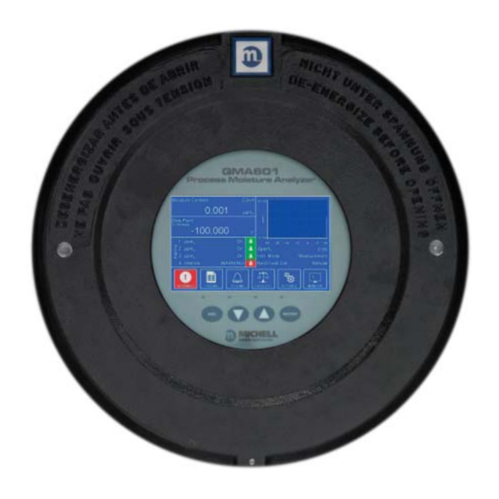
- Page 1 QMA601 Process Moisture Analyzer User’s Manual 97449 Issue 3 June 2018...
- Page 2 Please fi ll out the form(s) below for each analyzer that has been purchased. Use this information when contacting Michell Instruments for service purposes. Analyzer Code Serial Number Invoice Date Location of Analyzer Tag No Analyzer Code Serial Number Invoice Date...
- Page 3 © 2018 Michell Instruments This document is the property of Michell Instruments Ltd. and may not be copied or otherwise reproduced, communicated in any way to third parties, nor stored in any Data Processing System without the express written authorization of Michell Instruments Ltd.
-
Page 4: Table Of Contents
QMA601 User’s Manual Contents Safety ..........................viii Warnings ........................viii Electrical Safety ......................viii Pressure Safety ......................viii Hazardous Materials (WEEE, RoHS2 & REACH) ............. viii Calibration (Factory Validation) ..................ix Repair and Maintenance ....................ix Abbreviations ........................x INTRODUCTION ....................1 General ......................1 Theory of Operation ................... - Page 5 QMA601 User’s Manual 3.7.7 Field Calibration History ................44 3.7.8 About Screen ....................44 Sampling Guidelines ..................46 Measurement Cycle ..................49 3.10 Calibration Cycle ....................51 MAINTENANCE ....................53 Safety ......................54 Removal and Replacement of the Power Supply Fuse .......... 54 Replacing the Optional Contamination Trap ............
- Page 6 Measurement Cycle (Phase 2) Calibration Flow ...........50 Figure 43 Calibration Cycle (Phase 1) - Dried Sample Flow .........51 Figure 44 Calibration Cycle (Phase 2) - Sample Flow ..........52 Figure 45 Typical QMA601 Calibration Certificate ............58 97449 Issue 3, June 2018...
- Page 7 QMA601 User’s Manual Tables Table 1 Pop Up Keypad ..................20 Table 2 Main Screen Parameters ................23 Table 3 Large Parameter Display Mode ..............24 Table 4 Warning Screen ..................27 Table 5 Logging Screen ..................27 Table 6 Alarm Screen Parameters ................
-
Page 8: Safety
QMA601 User’s Manual Safety The analyzer is designed to be completely safe when installed and operated correctly in accordance with the information provided in this manual. This manual contains all the required information to install, operate and maintain this product. Prior to installation and use of this product, this entire manual should be read and understood. -
Page 9: Calibration (Factory Validation)
Michell Instruments can provide a fully traceable factory calibration service for the analyzer and it is recommended that this is considered at intervals of every year of the analyzer's life. Please contact your local Michell Instruments' office or representative for further details (www.michell.com). -
Page 10: Abbreviations
QMA601 User’s Manual Abbreviations The following abbreviations are used in this manual: alternating current pressure unit (atmosphere) barg pressure unit (=100 kP or 0.987 atm) gauge °C degrees Celsius °F degrees Fahrenheit European Union Hertz International Electrotechnical Commission kilogram pound... -
Page 11: Introduction
Minimal & Straightforward Maintenance Sophisticated analyzers are often complicated and require experience and special care in use, increasing cost of ownership. The QMA601 differs through its very uncomplicated approach to field service; the Desiccant Column is easy to replace via its mounting on the sampling panel. -
Page 12: Theory Of Operation
Trace moisture for Asymmetric Cycle variant, includes membrane filter and 3 way valve for purge gas. Our QMA601 sample systems facilitate regulation of pressure and flow, and the removal of contaminants, delivering a properly conditioned sample to the analyzer for reliable measurements, and trouble-free operation. -
Page 13: Sample Gas Path
QMA601 User’s Manual INTRODUCTION Sample Gas Path The QMA601 measurement system must be supplied with gas at the required pressure (to match that of its calibration) via the 1/4'' female NPT gas inlet on the flame arrestor. The flow is controlled automatically. -
Page 14: Installation
QMA601 User’s Manual INSTALLATION INSTALLATION Analyzer Storage Instructions In order for this product to be functional upon installation it should be stored in accordance with the guidelines below: • The product must be housed in a sheltered area, out of direct sunlight and rain. -
Page 15: Unpacking The Analyzer
Personnel must observe suitable lifting and handling precautions. The QMA601 is not designed as portable or transportable equipment. The product should be rigidly fixed in position as per the full installation instructions. The weight of the analyzer is 35kg (77lbs). Therefore, appropriate lifting and handling techniques should be used during the installation process. -
Page 16: Mounting The Analyzer
QMA601 User’s Manual INSTALLATION Mounting the Analyzer The analyzer is housed in an aluminum Exd enclosure suitable for wall or panel mounting. Four mounting points are available with M10 clearance holes on fixing centers of X = 308mm and Y = 312mm. -
Page 17: Hazardous Area/Location Safety
QMA601 User’s Manual INSTALLATION Hazardous Area/Location Safety This product is compliant for installation and use in a Hazardous Area/Location. All certificates awarded to this product should be fully examined prior to installation and use. WARNING: This product is certified safe for use in an ATEX Zone 1 and Zone 2 / Class I, Division 1 area only. -
Page 18: Electrical Safety
Mains 240 V AC 24 V DC 6.3 A A replacement fuse can be obtained by contacting Michell Instruments' technical support. 2.6.1 Equipment Ratings and Installation Details This equipment and all power isolation devices must be installed in a location and position that allows safe and easy access to their operation and is able to rigidly support the equipment. -
Page 19: Figure
QMA601 User’s Manual INSTALLATION The product enclosure is supplied with an external protective earthing/grounding terminal at the lower right hand side as shown in the figure below. As the first step of the electrical installation - connect this earthing/grounding terminal to plant earth/ ground by a minimum 4mm earth/ground bond strap. -
Page 20: Power Connection
QMA601 User’s Manual INSTALLATION This product is designed to be safe under the following conditions: between a temperature range of -40 to +60°C (-40 to +148°F), in maximum 80% relative humidity for temperatures up to +31°C (+88°F) decreasing linearly to 50% RH at +50°C (+122°F). -
Page 21: Other Electrical Connections
QMA601 User’s Manual INSTALLATION 2.6.3 Other Electrical Connections The power supply (shown below as a silver box) will not be in the 24 V DC version. Figure 5 Other Electrical Connections Analog Outputs OP2- OP2+ OP1- OP1+ External Pressure –... -
Page 22: Pressure Safety
QMA601 User’s Manual INSTALLATION Pin 1 Pin 8 Figure 6 RJ45 to screw terminal adapter connections Pin Signal Name Description Cable Wire Color TX+_D1 Transmit Data+ White with orange stripe TX-_D1 Transmit Data- Orange with white stripe or solid orange... -
Page 23: Gas Sample Connections
QMA601 User’s Manual INSTALLATION Unless otherwise specified the QMA601 is calibrated at a sample pressure of 3 barg (43.5 psig) on the gas inlet, and a back-pressure of 2 barg (29 psig) on the outlet. Operating the analyzer at a different pressure invalidates the calibration. - Page 24 QMA601 User’s Manual INSTALLATION Prolonged purging, or stripping and cleaning, followed by re-purging with gas may be necessary to remove the contamination. • Avoid sample gas streams that are already very close to the dew point or which have dispersed liquid within them. In such cases, sampling from fast loops and/or from downstream of existing catch pot/coalesce systems is always preferred.
-
Page 25: Operation
Section 2 and connected to a sample gas supply that is representative of the monitored process. General Operational Information Operation of the QMA601 is completely automated and once set-up requires little or no operator intervention. Michell Instruments... -
Page 26: First Time Operation
QMA601 User’s Manual OPERATION 3.1.1 First Time Operation To commence operation, proceed as follows: Connect the sampling line to the sample system. It is recommended to heat trace the sample gas line. Switch on the power supply to the analyzer. The Initializing Screen will appear. -
Page 27: Analyzer Set-Up
The back-pressure should also be adjusted to the value shown on the calibration certificate. Unless otherwise specified the QMA601 is calibrated at a sample pressure of 3 barg (43.5 psig) on the gas inlet, and a back-pressure of 2 barg (29 psig) on the outlet. -
Page 28: User Interface
QMA601 User’s Manual OPERATION User Interface The QMA601 features a 7” color display. 3.2.1 Interface Controls Figure 8 User Interface Four capacitive touch keys are used to navigate the menu system. Key presses are detected through the glass front panel, and are indicated by a blue LED above the key. -
Page 29: Enter' Key
QMA601 User’s Manual OPERATION 3.2.3 'ENTER’ Key ENTER Figure 10 ‘ENTER’ Key The ENTER key is used to navigate into menus, open keypads, cycle through options, and accept changes. For non-data entry options pressing the key moves to the next available option. -
Page 30: Pop Up Keypad
QMA601 User’s Manual OPERATION 3.2.5 Pop Up Keypad Allows the user to enter numerical data. The figures below the box indicate the minimum and maximum limits which can be entered. 000.0 0.0 to 300.0 Pop Up Keypad Figure 12 Action Note Moves cursor to last digit. -
Page 31: Menu Structure
QMA601 User’s Manual OPERATION Menu Structure LARGE DISPLAY PARAMETER 1 LARGE DISPLAY MAIN SCREEN PARAMETER 2 FULL SCREEN OVEN TEMP SENS GRAPH OVEN TEMP CNTL WARNINGS OUTPUT 1 ENCLOSURE TEMP LOGGING FLOW CONTROL OUTPUT 2 CELL PRESSURE OSCILLATOR COM ALARMS... -
Page 32: Description Of Measured Parameters
QMA601 User’s Manual OPERATION Description of Measured Parameters Moisture content ppm parts per million of H O by volume Moisture content ppm parts per million of H O by weight Moisture content mg/m milligrams of H O per cubic meter gas... -
Page 33: Table 2 Main Screen Parameters
Displays the current analyzer mode. Possible States: Measure – QMA601 is performing a measurement cycle. Cal Internal – QMA601 is performing a self-calibration using the Inst. Mode internal reference. Cal External – QMA601 is performing a self-calibration using an external reference. -
Page 34: Large Display Mode
QMA601 User’s Manual OPERATION 3.5.1 Large Display Mode Parameter 1 & 2 To access the large display mode for Parameter 1 and 2, press the key from the DOWN Main Screen. Cell Pressure barg Inst. Mode Measure O ppm 2 DP °C... -
Page 35: Figure 16 Full Screen Graph
QMA601 User’s Manual OPERATION Full Screen Graph This page displays a full screen graph of Parameter 1. To access the full screen graph, press the () key from the Main Screen. Full Screen Graph Figure 16 Michell Instruments... -
Page 36: Main Screen Sub Menus
QMA601 User’s Manual OPERATION Main Screen Sub Menus The following sub menus can be accessed from the Main Screen: • Warnings • Logging • Alarms • Field Cal • Settings • Monitor 3.6.1 Warning Screen This page is accessed through the 'Warnings' item on the Main Screen and is used enable or disable the internal alarms. -
Page 37: Logging Screen
QMA601 User’s Manual OPERATION The state of the internal alarm associated with each of the parameters above is indicated by the following icons: Icon Description Alarm disabled. Alarm enabled. No fault. Alarm enabled. Fault condition. Table 4 Warning Screen 3.6.2 Logging Screen This menu contains a record of the last 280 data points of the 'Log Parameter' value. -
Page 38: Alarm Screen
QMA601 User’s Manual OPERATION 3.6.3 Alarm Screen This menu allows the internal alarm parameters to be set. It is accessed through the 'Alarms' item on the Main screen. This screen is accessed by pressing the key from the Configuration Screen. -
Page 39: Field Calibration Screen
QMA601 User’s Manual OPERATION 3.6.4 Field Calibration Screen This menu allows the field calibration parameters to be set and activated if necessary. It is accessed through the 'Field Cal' item on the Main screen. Depending upon the field calibration settings some parameters may become inactive. -
Page 40: Table 7 Calibration Screen Parameters
QMA601 User’s Manual OPERATION Parameter Description Starts a calibration procedure if a manual calibration has been selected. Calibrate Toggles data hold mode. This determines whether the last valid measurement is held while a calibration is carried out. Analog O/P Available Options: On, Off... - Page 41 QMA601 User’s Manual OPERATION If Analog O/P Hold is turned off then the ‘Hold Cycles’ selection box is hidden, as shown below: Figure 21 Field Calibration Screen 2 Hold Cycles – If Analog O/P Hold is selected, the user can select for how many cycles after the calibration the last measured value is held for.
-
Page 42: Figure
QMA601 User’s Manual OPERATION If a manual calibration is selected then both the ‘Interval’ and ‘Hour’ selection boxes are hidden, as shown above. If an automatic calibration is selected then the “Calibrate”, “Cal Source” and “Ext Ref” selection boxes are hidden, as shown below:... -
Page 43: Monitor Screen
Live delta frequency reading: the beat frequency difference Delta Frequency(Hz) between the sample and reference phase. Enclosure Temperature Live QMA601 enclosure temperature. (0C) Live flow rate reading. Flow Rate (ml/min) Live internal pressure transducer reading. Cell pressure (barg) Live external pressure reading. -
Page 44: Settings Menu
QMA601 User’s Manual OPERATION Settings Menu The settings menu is accessed through the Settings item on the main screen. Figure 26 Settings Menu Screen Allows access to the following sub menus to change instrument settings. • Measurement • Outputs •... -
Page 45: Figure 27 Measurement Screen
QMA601 User’s Manual OPERATION Figure 27 Measurement Screen Parameter Description The settings menu is accessed through the Settings item on the main screen. Available Options: Air, Ar, CH CO, CO , He, Kr, N , Ne, NH , NO, N... - Page 46 QMA601 User’s Manual OPERATION 3.7.1.1 Carrier Gas Used to select a different carrier gas. When the Carrier Gas option is selected the page shown below is opened. Carrier Gas Screen Figure 28 There are 20 different preset gases the user can choose from, along with 3 user definable presets: •...
- Page 47 QMA601 User’s Manual OPERATION NB. If User 1, 2 or 3 is selected as the carrier gas then a new parameter box will appear underneath the carrier gas toggle box called ‘User Gas’. This can be seen below. Figure 29...
- Page 48 QMA601 User’s Manual OPERATION Figure 30 External Options If the fixed option is selected the ‘Ext. 4mA’ and ‘Ext. 20mA’ selection boxes are hidden and replaced with the ‘Fixed’ selection box as shown below: Fixed Options Figure 31 If the ‘Atmos.’ option is selected the ‘Fixed’, ‘Ext. 4mA’ and ‘Ext. 20mA’ selection boxes...
-
Page 49: Outputs Screen
QMA601 User’s Manual OPERATION User Gas Setup Screen Figure 33 • Gas – Allows the user to enter a unique name for the gas using the onscreen keypad. • Molecular Weight – Allows the user to enter the molecular weight of the gas using the onscreen keypad. -
Page 50: Figure 34 Outputs Screen
QMA601 User’s Manual OPERATION Outputs Screen Figure 34 Parameter Description Selects the output channel to check and modify. Output Selector Available Options: Output 1, Output 2 Selects the parameter tracked by the output channel. Parameter Available Options: H2O ppmv, H2O ppmw, mg/m3, WVP Pa, H2O lbs/ MMscf, DP, Oven, Flow, Cell Pr., Ext. -
Page 51: Hmi Screen
The HMI Screen allows the setting of the display language, parameters and measurement units. It is accessed from either the HMI item on the Settings menu or directly during the QMA601 warm up procedure. This screen is accessed by pressing the... -
Page 52: Table 11 Hmi Setup Screen Parameters
QMA601 User’s Manual OPERATION Parameter Description Sets the HMI language Language Available Options: English, Japanese Selects the time scale of the chart. Changing the chart period will remove all current data from the chart. Chart Period Available Options: 5 mins, 30 mins, 1 hr, 5 hrs, 10 hrs, 24 hrs Select the signal smoothing level. -
Page 53: Real Time Clock Screen
QMA601 User’s Manual OPERATION 3.7.4 Real Time Clock Screen The Real Time Clock screen is used to set the current date and time parameters for the instrument. It is accessed through the RTC item on the Settings menu. This screen is accessed by pressing the key from the Configuration Screen. -
Page 54: Software Communications Screen
QMA601 User’s Manual OPERATION 3.7.5 Software Communications Screen The Software Communication screen is used to set the physical method the QMA601 uses to communicate with external software. It is accessed through the 'SW COMMS' item on the Settings menu. Figure 37... -
Page 55: Field Calibration History
QMA601 User’s Manual OPERATION Parameter Description Instrument's static IP address on the network. IP Address Subnet mask of network that the instrument is on. Subnet Mask The default gateway of the network that the instrument is on. Default Gateway Saves Ethernet settings. -
Page 56: Sampling Guidelines
Sampling Guidelines The QMA601 is designed to operate in a flowing gas stream and is suitable for the measurement of the moisture content of a wide variety of gases. In general, if the gas (in conjunction with water vapor) is not corrosive to the sampling system and the sensor base metals then it will be suitable for measurement by the QMA601. - Page 57 Michell Instruments supplies a range of precision pressure fittings suitable for use with the QMA601. Contact Michell Instruments for details of the items available.
- Page 58 Therefore it is recommended to use the smallest possible tube diameter to minimize the previously mentioned effects. This must be balanced with the desired response speed. Depending on the configuration 1/8” tube diameter is recommended. Please contact Michell Instruments if further recommendations are needed. • Ambient temperature variation Fluctuations in ambient temperature conditions can cause detectable changes in the sample gas' moisture content due to heating/cooling of the sample system.
-
Page 59: Measurement Cycle
QMA601 User’s Manual OPERATION Measurement Cycle At the beginning of a measurement cycle V1 is energized. This allows the dried sample gas to be routed to the sensor cell for or the reference phase duration as shown by the red line in Figure 41 . During this first phase of the measurement cycle the difference in frequency between the sensor and reference crystals is measured. - Page 60 QMA601 User’s Manual OPERATION After a 30 second sampling period, V1, V2, and V3, the reference phase is de-energized. This cuts off the dried gas supply to the sensor cell and V3 is energized connecting the sample gas (red line - see Figure 42) to the sensor cell for the sample phase duration.
-
Page 61: Calibration Cycle
QMA601 User’s Manual OPERATION 3.10 Calibration Cycle To maintain the accuracy of the analyzer, the unit can self calibrate and adjust its internal reference based on the result. This is achieved as follows: An internal moisture generator uses a permeation tube to generate a nominal moisture content of 0.5, 5 or 50 ppm... - Page 62 QMA601 User’s Manual OPERATION At the close of this 30 second sampling period, V1 is de-energized, and V2 is energized so that the reference gas from the moisture generator is now routed to the sensor cell. This is the beginning of the calibration phase, see Figure 44.
-
Page 63: Maintenance
The QMA601 stores this correction factor and automatically compensates subsequent sample readings for any offset that may have occurred to the factory calibration. - Page 64 In addition to general maintenance procedures which involve the cleaning of the analyzer’s casing and display, there are a number of parts in the QMA601 which can be removed and replaced by the operator.
-
Page 65: Safety
Replacement fuses can be obtained by contacting Michell Instruments' technical support. Replacing the Optional Contamination Trap The contamination trap is part of the QMA601 additionally supplied sample system. Refer to the application specific sample system design requirements for the removal and fitting of this part. -
Page 66: Removal And Replacement Of The Desiccant Column
QMA601 User’s Manual MAINTENANCE If the contamination trap is to be returned to Michell Instruments, or a Michell Instruments' approved service center form, the F0121 Decontamination Certificate must be completed and sent with the returned trap. Removal and Replacement of the Desiccant Column... - Page 67 QMA601 User’s Manual MAINTENANCE Lift out the Desiccant Column. Replacement Before fitting the new Desiccant Column, push the new snubber on to the top VCR fitting, and fit a new VCR face seal to the bottom VCR fitting. NOTE: Be careful when removing the snubber, as the desiccant will pour out of the VCR fitting if the dryer is tipped up.
-
Page 68: Calibration
A calibration certificate bearing the calibration data points is issued with each analyzer. If required, an option is available to specify the number of required calibration points by contacting Michell Instruments. A list of worldwide Michell Instruments’ offices is provided at www.michell.com. -
Page 69: Figure 45 Typical Qma601 Calibration Certificate
QMA601 User’s Manual CALIBRATION Typical QMA601 Calibration Certificate Figure 45 Michell Instruments... -
Page 70: Shipping
QMA601 User’s Manual SHIPPING SHIPPING Preparation for Shipping and Packing if Not Supplied as a Sample System For shipping purposes, the analyzer should be packed into its original crate as this will provide the recommended degree of protection during transit. -
Page 71: Application Software Overview
QMA601 User’s Manual APPLICATION SOFTWARE APPLICATION SOFTWARE OVERVIEW With the QMA Application Software you can: • Read and edit all main analyzer parameters • Chart and log all main analyzer parameters • Perform a field calibration • Reset the analyzer to factory defaults Communication between the application software and analyzer is via Modbus RTU over RS485, USB, or Ethernet where available. -
Page 72: Getting Started
QMA601 User’s Manual APPLICATION SOFTWARE Getting Started On launching the software the connection console will appear, allowing you to establish communications between the software and QMA analyzer. Choose the Modbus slave address (default is 1). Select the Connection Method for the analyzer and associated options. -
Page 73: Connection Method (Serial Connection (Rs485 Or Tcp)
QMA601 User’s Manual APPLICATION SOFTWARE 7.3.1 Connection Method (Serial Connection (RS485 or TCP) Select the connection method for the analyzer. 7.3.1.1 RS485 Connection An RS485 to RS232 converter must be used when connecting to a computer's built in serial port, or when connecting to an RS232 to USB adaptor. -
Page 74: Main Window
QMA601 User’s Manual APPLICATION SOFTWARE Main Window The application software will automatically begin acquiring, displaying and charting data from the analyzer once a connection has been established. Data acquisition occurs approximately every 2 seconds. The chart update rate is 2 seconds but this may be changed by using the chart options window. -
Page 75: Using The Chart
QMA601 User’s Manual APPLICATION SOFTWARE Using the Chart Chart mode buttons The chart defaults to plot mode. To change the chart mode, click one of the buttons along the top of the chart, described below. Function Description Puts chart into live plot mode... -
Page 76: Chart Options Window
QMA601 User’s Manual APPLICATION SOFTWARE 7.5.1 Chart Options Window The Chart Options Window allows the user to configure the following chart properties: Function Description Allows the user to show or hide data series from the chart. Show/hide series Tick to show, untick to hide... -
Page 77: Data Logging
QMA601 User’s Manual APPLICATION SOFTWARE Data Logging Click the 'Data Logging' button on the Main Window to launch the Data Logging Setup Window. Choosing a log file filename Choose a log file manually by clicking the button. Click the 'Auto generate' button to generate a filename based on the current date and time. -
Page 78: Configuring Logging Stop Time
Parameters / Field Calibration Analyzer parameters may be viewed and edited via this window. All of these options mirror the options available on the QMA601 HMI and to refer to the relevant pages for more information. Current (live) values are shown in the 'Value now' column. New values may be entered in the 'Adjust' column. -
Page 79: Field Calibration
QMA601 User’s Manual APPLICATION SOFTWARE 7.7.1 Field Calibration This window allows manual analyzer calibrations to be performed, and settings for automatic calibrations configured. These options mirror the options in section 3.6.4. Michell Instruments... - Page 80 QMA601 User’s Manual APPENDIX A Appendix A Technical Specifi cations 97449 Issue 3, June 2018...
-
Page 81: Appendix A Technical Specifi Cation
QMA601 User’s Manual APPENDIX A Appendix A Technical Specifi cation Performance Measurement technology Fast Response Quartz Crystal Microbalance Calibrated range* 0.1 to 700 ppm Measurement range 0.1 to 2000 ppm ±10% of reading from 1 to 2000 ppm Accuracy ±0.1 ppm between 0.1 &... - Page 82 QMA601 User’s Manual APPENDIX A Mechanical Specifications Type GUB Flameproof Exd Enclosure Cast copper-free aluminum LM25 (EN AC-42000), less than 0.6 Lid & Body magnesium Heat resistant, explosion proof, polyester coated, IP66, NEMA 4 Glass Window Analyzer Gas Connections 1/8” NPT...
-
Page 83: Appendix B Hazardous Area Certifi Cation
QMA601 User’s Manual APPENDIX B Appendix B Hazardous Area Certifi cation Michell Instruments... -
Page 84: Product Standards
Appendix B Hazardous Area Certifi cation The QMA601 is certified compliant to the ATEX Directive (2014/34/EU) and IECEx for use within Zone 1 and Zone 2 / Class I, Division 1 Hazardous Areas, and has been assessed so by TRaC Compliance (Notified Body 0891). -
Page 85: Maintenance And Installation
Maintenance and Installation The QMA601 must only be installed by suitably qualified personnel and in accordance with the instructions provided and the terms of the applicable product Certificates. Maintenance and servicing of the product must only be carried out by suitably trained personnel or returned to an approved Michell Instruments' Service Center. - Page 86 QMA601 User’s Manual APPENDIX C Appendix C Modbus Register Map 97449 Issue 3, June 2018...
-
Page 87: Appendix C Modbus Holding Register Map
Appendix C Modbus Holding Register Map All the data values relating to the QMA601 are stored in holding registers. Each of these registers is two bytes (16-bits wide). Some of these registers contain instrument specific values e.g. its own unique system address, IP address values, etc. Others registers hold specific real time data such as temperature. - Page 88 QMA601 User’s Manual APPENDIX C Last Cal - 1 Details Last Cal – 2 Day/Month/Year Last Cal – 2 Details Last Cal – 3 Day/Month/Year Last Cal – 3 Details Last Cal – 4 Day/Month/Year Last Cal – 4 Details User Gas Flow Correction Val1 0.100 to 10.000...
- Page 89 QMA601 User’s Manual APPENDIX C *Osc Table1 DeltaF 10 Hi Word 0.0001 to 2000.0000 *Osc Table1 DeltaF 10 Lo Word “ *Osc Table1 DeltaF 11 Hi Word 0.0001 to 2000.0000 *Osc Table1 DeltaF 11 Lo Word “ *Osc Table1 DeltaF 12 Hi Word 0.0001 to 2000.0000...
- Page 90 QMA601 User’s Manual APPENDIX C *Osc Table2 DeltaF 03 Lo Word “ *Osc Table2 DeltaF 04 Hi Word 0.0001 to 2000.0000 *Osc Table2 DeltaF 04 Lo Word “ *Osc Table2 DeltaF 05 Hi Word 0.0001 to 2000.0000 *Osc Table2 DeltaF 05 Lo Word “...
- Page 91 QMA601 User’s Manual APPENDIX C *Osc Table2 Cal Reference Phase Time 10 to 240 seconds *Osc Table2 Cal Settling Cycles 4 to 240 cycles *Osc Table2 Cal Calibration Cycles 4 to 60 cycles *BLANK Dont Care *Osc Table2 Cal Cell Pressure Reading LoW 0.00 to 10.00 barG...
- Page 92 QMA601 User’s Manual APPENDIX C Ref Seconds Countdown Pressure Reading of cell in set unit See App A Sample Seconds Countdown Cal Settling / Calibration Cycles Countdown System Status Register Warning Flags Register Current Flow Correction value Moist Gen Value Read After Cal – Hi Word For cal use Moist Gen Value Read After Cal –...
-
Page 93: Table 18 Modbus Register Map
QMA601 User’s Manual APPENDIX C DeltaF Log t8 Lo Word For cal use DeltaF Log t9 Hi Word For cal use DeltaF Log t9 Lo Word For cal use Ppmv Log t0 Hi Word For cal use Ppmv Log t0 Lo Word... - Page 94 QMA601 User’s Manual APPENDIX C Register Configuration A A1 — Unsigned Short. Range = 0 to 65535 A2 — Unsigned Short/10. Range = 0 to 6553.5 A3 — Unsigned Short/100. Range = 0 to 655.35 A4 — Unsigned Short/1000. Range = 0 to 65.535 A5 —...
- Page 95 QMA601 User’s Manual APPENDIX C Register Configuration C — Modbus Configuration Instrument Address (IA) Protocol Type (PT) 1 to 31 (1=def) 00=RS485 01=USB VCP 10= Ethernet Register Configuration D — System Configuration Temperature/Dew Point units (TU) Pressure for Dew-Point Calculations (PS)
- Page 96 QMA601 User’s Manual APPENDIX C Register Configuration E — Alarm Configuration Note: Alarm 4 is a system fault/warning alarm and is configured in register 9 (Configuration M) Alarm1 Parameter (A1) Alarm2 Parameter (A2) 0000 = Moisture – PPMv (def) 0000 = Moisture – PPMv...
- Page 97 QMA601 User’s Manual APPENDIX C Register Configuration H — Time (hours/minutes) Hours Number (HH) Minutes Number (MM) 00 to 23 00 to 59 Register Configuration I — 32 bit Precision Floating Point Representation IEEE-754 single precision floating point format. This format is 'Big Ended' which means that the high byte is at a lower address in memory than the Lo byte, and is represented as such in the register memory map.
- Page 98 QMA601 User’s Manual APPENDIX C Register Configuration J — Date Date Number (DD) Month Number (MM) 1 to 31 1 to 12 Year Number (YY) or Seconds 00-99 for year or 00-59 for seconds Register Configuration K — Historic Calibration Log — Details...
- Page 99 QMA601 User’s Manual APPENDIX C Register Configuration M — System Warning Flags (Register 230), Analyzer Status Alarm Relay Selection Mask (Register 9) 1=Warning or fault, 0=OK Warning Condition Oven temperature unstable. Oven temperature has not been 0001 stable within ±0.01C of setpoint for continuous 5 minutes. (Process alarms de-energized, both analog outputs at fault condition Enclosure temperature too high.
- Page 100 QMA601 User’s Manual APPENDIX C Register Configuration P1 — Next Calibration Configuration Manual or Auto (MA) Internal or External (IE) 0 = Manual 0 = Internal 1 = Auto 1 = External Data Hold (DH) Data Hold Additional Cycles (AC)
- Page 101 QMA601 User’s Manual APPENDIX C 10 = Force Analog Output 1 to 4 mA** 11 = Force Analog Output 1 to 20 mA** 12 = Force Analog Output 2 to 4 mA** 13 = Force Analog Output 2 to 20 mA**...
- Page 102 QMA601 User’s Manual APPENDIX C Register Configuration U — Internal Logging Configuration/Service Interval Days DeltaF and ppm Log Interval in cycles (DP) Ram Buffer Log parameter (RL) Range is 1 to 15 cycles. (for CAL use, def = 1) 0000 = Moisture – PPMv (def) 0001= Moisture - PPMw 0010 = Moisture –...
-
Page 103: Set Points And Ranges
QMA601 User’s Manual APPENDIX C Set Points and Ranges Set points and ranges for Analog Outputs, Alarms, Fixed User Pressure, Cell Pressure and External (line) Pressure sensor. Adjustment Unit Default Values Register Range Register Type Range/Res. 0.0 to 3000.0 0.0 to 2000.0... -
Page 104: Gases For Gas Correction Values
QMA601 User’s Manual APPENDIX C Gases for Gas Correction Values Gases for gas correction values, indexed 0 to 23. If a USER gas is selected then the instrument will use the gas correction values that are set in the respective registers 38, 39 and 40 for the Flow correction and at registers 41, 42 and 43 for the molecular weights. -
Page 105: Appendix D Quality, Recycling, Compliance & Warranty Information
QMA601 User’s Manual APPENDIX D Appendix D Quality, Recycling, Compliance & Warranty Information Michell Instruments... - Page 106 APPENDIX D Appendix D Quality, Recycling, Compliance & Warranty Information Michell Instruments is dedicated to complying to all relevant legislation and directives. Full information can be found on our website at: www.michell.com/compliance This page contains information on the following directives: •...
-
Page 107: Appendix E Return Document & Decontamination Declaration
QMA601 User’s Manual APPENDIX E Appendix E Return Document & Decontamination Declaration Michell Instruments... - Page 108 Has the equipment been cleaned and decontaminated? NOT NECESSARY Michell Instruments will not accept instruments that have been exposed to toxins, radio-activity or bio-hazardous Work will not be carried out on any unit that does not have a completed decontamination declaration.
-
Page 109: Appendix F Calculating Conversion Factors For Gas Mixes
QMA601 User’s Manual APPENDIX F Appendix F Calculating Conversion Factors for Gas Mixes Michell Instruments... - Page 110 Appendix F Calculating Conversion Factors for Gas Mixes Setting the correct flow rate is crucial to correct operation of the QMA601. If the gas being sampled contains multiple components, then the conversion factor must be calculated and entered as a ‘user’...
- Page 112 http://www.michell.com...
Need help?
Do you have a question about the QMA601 and is the answer not in the manual?
Questions and answers