Table of Contents
Advertisement
Advertisement
Table of Contents

Subscribe to Our Youtube Channel
Related Manuals for Michell Instruments XZR400 Series


Summary of Contents for Michell Instruments XZR400 Series
- Page 1 XZR400 Series Oxygen Analyzers User’s Manual 97472 Issue 3 August 2018...
- Page 2 Please fi ll out the form(s) below for each instrument that has been purchased. Use this information when contacting Michell Instruments for service purposes. Instrument Code Serial Number Invoice Date Location of Instrument Tag No Instrument Code Serial Number Invoice Date...
- Page 3 © 2018 Michell Instruments This document is the property of Michell Instruments Ltd. and may not be copied or otherwise reproduced, communicated in any way to third parties, nor stored in any Data Processing System without the express written authorization of Michell Instruments Ltd.
-
Page 4: Table Of Contents
XZR400 Series User’s Manual Contents Safety ..........................viii Electrical Safety ......................viii Pressure Safety ......................viii Temperature Safety ....................viii Toxic Materials ......................viii Repair and Maintenance ..................... viii Calibration ......................... viii Safety Conformity ...................... viii Abbreviations ........................ix Warnings ..........................x INTRODUCTION ....................1... - Page 5 4.1.2 Diagnosis of the MSRS Sensor Status - Screen pages 3.2.4 to 3.2.7 ..... 59 MAINTENANCE ....................62 Troubleshooting Guide / Failure Analysis ............62 Tables Table 1 XZR400 Series MSRS Assembly ..............5 Table 2 RS232 Commands ..................75 Michell Instruments...
- Page 6 MSRS Sensor....................4 Figure 3 MSRS Dimensions ..................4 Figure 4 MSRS Wiring ....................4 Figure 5 XZR400 Series MSRS Assembly ..............5 Figure 6 Dimensions - XZR400A1 ................7 Figure 7 Dimensions - XZR400A2 ................8 Figure 8 Dimensions - XZR400A2 with External Pump Option ........9 Figure 9 Dimensions - XZR400A3 ................10...
- Page 7 XZR400 Series User’s Manual Figure 55 Main Page ....................85 Figure 56 Control Parameters Page ................85 Figure 57 Main Menu ....................85 Figure 58 DP Sensor Page ..................86 Appendices Appendix A Technical Specifi cations ................67 Appendix B Modbus (RTU) over RS485 ................. 70 Port Confi...
-
Page 8: Safety
Repair and Maintenance The instrument must be maintained either by the manufacturer or an accredited service agent. Refer to www.michell.com for details of Michell Instruments’ worldwide offi ces contact information. Calibration The recommended calibration (or verifi cation) interval for the analyzer is 1 to 3 months depending on the location and application in which the instrument is used. -
Page 9: Abbreviations
XZR400 Series User’s Manual Abbreviations The following abbreviations are used in this manual: alternating current Ampere barg pressure unit (=100 kP or 0.987 atm) gauge °C degrees Celsius °F degrees Fahrenheit liters per hour l/min liters per minute milliampere minute... -
Page 10: Warnings
XZR400 Series User’s Manual Warnings The following general warnings listed below are applicable to this instrument. They are repeated in the text in the appropriate locations. Where this hazard warning symbol appears in the following sections, it is used to indicate areas where potentially hazardous operations need to be carried out. -
Page 11: Introduction
INTRODUCTION INTRODUCTION The XZR400 Series Trace Oxygen Analyzer is designed to measure oxygen as an inpurity in nitrogen, carbon dioxide, argon, helium or other inert gases. Analysis is both quick and stable, utilizing our metallic sealed reference sensor (MSRS), with no requirement for reference air. -
Page 12: Operating Principle
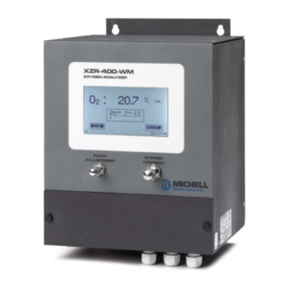
XZR400 Series User’s Manual INTRODUCTION The XZR400 Series includes the following front panel mounted items: • Liquid crystal touchscreen display • Flow adjustment valve • Bypass control valve Operating Principle The analyzer operates on the zirconium oxide (zirconia) principle. A sample of the gas to be measured is connected to the inlet port of the analyzer. The sample gas fl... -
Page 13: The Msrs Technology
XZR400 Series User’s Manual INTRODUCTION The MSRS Technology The zirconium oxide sensors are often referred to as the ‘high temperature’ electrochemical sensors. The principle is based on the Nernst principle [W. H. Nernst (1864-1941)]. Zirconium oxide sensors use a solid state electrolyte and are stabilized with yttrium oxide. -
Page 14: Figure 2 Msrs Sensor
XZR400 Series User’s Manual INTRODUCTION Figure 2 MSRS Sensor Conventional zirconium oxide sensors require an air reference on one side of the sensor with the sample on the other. This provides a known constant on one side. The Michell MSRS does not require an air reference but instead utilizes a metal, and its oxide, sealed in the zirconium sheath. -
Page 15: Table 1 Xzr400 Series Msrs Assembly
XZR400 Series User’s Manual INTRODUCTION Figure 5 shows the MSRS and its S thermocouple installed in a 4-hole aluminum tube. This confi guration has the part number XZR400-SMP. Any reference to the MSRS sensor refers to this complete assembly which is considered solid state and non user-serviceable. -
Page 16: Installation
Carefully read the following guidelines before installing the analyzer. If you are not sure about the installation conditions and other important factors please contact a Michell Instruments’ Application Engineer or a Michell Instruments’ representative prior to the installation. The following list will help you to identify the recommended preparation steps: •... -
Page 17: Dimensions - Xzr400A1
XZR400 Series User’s Manual INSTALLATION Dimensions - XZR400A1 362mm + 50mm for cable clearance (14.25” + 1.96”) XZR-400-RM OXYGEN ANALYZER FLOW BYPASS ADJUSTMENT Handles protrude 40mm (1.6”) 483mm (19”) Dimensions - XZR400A1 Figure 6 2.3.1 Installing the XZR400A1 Choose your installation site carefully following the recommendations above. Once installed into the rack, there should be at least 2U clearance spaces from other equipment above and below the instrument. -
Page 18: Dimensions - Xzr400A2
XZR400 Series User’s Manual INSTALLATION Dimensions - XZR400A2 220mm (8.66”) 180mm 236mm (7.09”) 152mm (9.29”) (5.98”) 201mm (7.91”) BYPASS FLOW CONTROL ADJUSTMENT 110mm (4.33”) 30mm 30mm 30mm (1.18”) (1.18”) (1.18“) GAS IN GAS OUT Figure 7 Dimensions - XZR400A2 97472 Issue 3, August 2018... -
Page 19: Installing The Xzr400A2
XZR400 Series User’s Manual INSTALLATION 490mm (19.29”) 470mm (18.50”) 220mm (8.66”) 180mm 201mm (7.09”) 152mm (7.91”) (5.98”) 20mm (.79”) BYPASS FLOW CONTROL ADJUSTMENT 470mm (18.50”) 60mm (2.4”) 53mm (2.09”) Particulate filter 230 V AC 50 Hz 6mm (0.24”) tube Gas Inlet Analyzer power supply 4 x Ø... -
Page 20: Dimensions - Xzr400A3
XZR400 Series User’s Manual INSTALLATION Dimensions - XZR400A3 203mm 260mm (7.9”) (10.2”) 236mm (9.3”) Dimensions - XZR400A3 Figure 9 Dimensions - XZR400A4 300mm 350mm (11.8”) (13.8”) Dimensions - XZR400A4 Figure 10 97472 Issue 3, August 2018... -
Page 21: Operating Requirements
Please consult Michell Instruments if a sampling system is required. Install the sampling system as close as possible to the XZR400 Series analyzer to ensure the best possible measurement results. NOTE: Michell Instruments can provide a suitable sampling system when delivering the analyzer. -
Page 22: Connections To The Xzr400A1
XZR400 Series User’s Manual INSTALLATION Connections to the XZR400A1 2.8.1 Front Panel Item Description Touchscreen LCD Flow adjustment needle valve Bypass control needle valve Figure 11 Front Panel XZR400A1 2.8.2 Back Panel An electrical connection terminal is provided for signal and alarm connections. -
Page 23: Gas Inlet, Outlet And Bypass Gas Connections
XZR400 Series User’s Manual INSTALLATION 2.8.3 Gas Inlet, Outlet and Bypass Gas Connections The fl uidic system comprises 2 fl ow control valves (sensor fl ow and by-pass fl ow), an electronic fl ow meter and a sensor. The gas connections are stainless steel Swagelok 1/8"... -
Page 24: Electrical Terminal Block
XZR400 Series User’s Manual INSTALLATION 2.8.4 Electrical Terminal Block 10 11 12 13 14 15 16 Item Function (+) 4-20 mA Output No 1. Measurement proportional to the chosen O scale. 0 V from the 4-20 mA Output No 1 & 2. -
Page 25: Sample Path
XZR400 Series User’s Manual INSTALLATION 2.8.7 Sample Path The MSRS sensor is placed inside an oven in which the gases to be analyzed are circulated. The oven consists of a gas inlet head and a outlet plate. 3 Viton O-rings ensure the sealing of this device (2 for the inlet and 1 for the outlet). -
Page 26: Figure 17 Sample Path With Pump Fitted Xzr400A1
XZR400 Series User’s Manual INSTALLATION XZR400A1 WITH INTERNAL PUMP: • 3 Swagelok 6mm stainless steel bulkhead unions (1 gas inlet and 2 gas outlets) - on the rear panel • 1 sampling pump (3 l/min) • 2 electrovalves XZR400A1 Electronic flowmeter 0-12 l/h N.C. -
Page 27: 2.8.7.1 Signal Processing Path
XZR400 Series User’s Manual INSTALLATION 2.8.7.1 Signal Processing Path The values of oxygen concentration and fl ow passing through the sensor are displayed continuously. On specifi c screen pages the following control parameters are displayed: • Oven temperature • Ambient temperature (corresponding to the thermocouple junction temperature) •... -
Page 28: Connections To The Xzr400A2
XZR400 Series User’s Manual INSTALLATION Connections to the XZR400A2 The connections are shown below. Item Description Graphic touch screen - displays measurement and menus. Multi-turn knurled knob for fi ne adjustment of the gas fl ow. Multi-turn knurled knob for basic adjustment of the gas fl ow (bypass). -
Page 29: Gas Sample Inlet And Outlet Fittings
XZR400 Series User’s Manual INSTALLATION 2.9.1 Gas Sample Inlet and Outlet Fittings The gas path consists of 2 fl ow control valves (sensor fl ow and by-pass fl ow), a sensor and an electronic fl owmeter. For the gas inlet and the outlet connections, Swagelok stainless steel 6mm bulkhead unions are used, which guarantees perfect sealing and easy removal. -
Page 30: Electrical Terminal Block
XZR400 Series User’s Manual INSTALLATION 2.9.2 Electrical Terminal Block The terminal block is located by removing the front panel cover. 10 11 12 13 14 15 16 Item Function Connection to the MSRS cell; system reserved (TC+ – orange). Connection to the MSRS cell; system reserved (common – white). -
Page 31: D-Sub Da15 Plug
XZR400 Series User’s Manual INSTALLATION 2.9.4 D-Sub DA15 plug This optional D-Sub DA15 male plug (15 pin) is used to connect a second 4-20 mA output, a total pressure adjustment inlet, and the analyzer's auto adjustment terminals, as well as automatic scale switching operations. -
Page 32: Signal Processing Path
XZR400 Series User’s Manual INSTALLATION 2.9.6 Signal Processing Path The values of oxygen concentration and fl ow passing through the sensor are displayed continuously. On specifi c screen pages the following control parameters are displayed: • Oven temperature • Ambient temperature (corresponding to the thermocouple junction temperature) •... -
Page 33: Connections To The Xzr400A3
XZR400 Series User’s Manual INSTALLATION 2.10 Connections to the XZR400A3 2.10.1 Front Panel The front panel features are shown below: Item Description Carrying handle. Multi-turn knurled knob for basic adjustment of the gas fl ow (bypass). Graphic touch screen - displays measurement and menus. -
Page 34: 2.10.2 Side Panel
XZR400 Series User’s Manual INSTALLATION 2.10.2 Side Panel The side panel connections are shown below: Item Description ON/OFF button. Mains socket (90-132/187-264 VA, automatic range switching, 47/63 Hz). Inlet fi tting for the gas sample to be analyzed (for 6mm tube). -
Page 35: 2.10.3 Electrical Terminal Block
XZR400 Series User’s Manual INSTALLATION 2.10.3 Electrical Terminal Block 10 11 12 13 14 15 16 Item Function Connection to the MSRS cell; system reserved (TC+ – orange). Connection to the MSRS cell; system reserved (common – white). Connection to the MSRS cell; system reserved (reference – blue). -
Page 36: Connections To The Xzr400A4-Transportable
XZR400 Series User’s Manual INSTALLATION 2.11 Connections to the XZR400A4-Transportable Item Description Graphic touch screen - displays measurement and menus. Multi-turn knurled knob for fi ne adjustment of the gas fl ow. Multi-turn knurled knob for basic adjustment of the gas fl ow (bypass). -
Page 37: 2.11.1 Electrical Terminal Block
XZR400 Series User’s Manual INSTALLATION 2.11.1 Electrical Terminal Block Item Function General alarm contact. Alarm No.1 contact terminal. Shared contact for Alarm No.1 and Alarm No.2. Alarm No.2 contact terminal. Not connected. Optional Flow alarm. Optional 4-20 mA output #1 positive (+). -
Page 38: Mains Power Supply - Xzr400A1, Xzr400A3 & Xzr400A4
XZR400 Series User’s Manual INSTALLATION 2.12 Mains Power Supply - XZR400A1, XZR400A3 & XZR400A4 The AC power supply is a push fi t into a power input socket as shown below. The method of connection is as follows: POWER INPUT ... -
Page 39: 2.12.1 Analog Outputs Connections
XZR400 Series User’s Manual INSTALLATION 2.12.1 Analog Outputs Connections The analyzer is supplied with 1 or 2 off 4-20 mA outputs. The signal outputs will be connected to external systems that can potentially infl uence the operation of the process. -
Page 40: 2.12.2 Alarm Output Connections
XZR400 Series User’s Manual INSTALLATION 2.12.2 Alarm Output Connections Two alarm relays are provided and are connected to the instrument via the terminal block on the back panel of the analyzer. The signal outputs will be connected to external systems that can potentially infl... -
Page 41: Gas Connection
To ensure that the sample gas is properly conditioned a sampling system might be required. Contact Michell Instruments if you wish to order a suitable sampling system. Sample gas connections are made via the gas input and gas output ports located on the back panel (XZR400A1), bottom panel (XZR400A2), side panel (XZR400A3) or front panel (XZR400A4) of the analyzer. -
Page 42: Operation
fl ow. The XZR400 Series Analyzers are suitable for the measurement of oxygen in a wide variety of clean and dry gases. It will not contaminate high purity gases and is safe for use in critical semiconductor and fi... -
Page 43: Powering-Up The System
XZR400 Series User’s Manual OPERATION Powering-up the System Carefully check the electrical connection before applying the power. Switch the external disconnecting device supplying power Wall Mount Version to the analyzer. This device does not have a built-in on/off switch. Portable and Rack... -
Page 44: Warm-Up Period
XZR400 Series User’s Manual OPERATION Warm-Up Period Upon power up, the screen appears as shown below. The analyzer performs a series of internal checks for about 5 seconds. NOTE: Touch the French or English area to display the menu in the required language. -
Page 45: Figure 31 Sample Flow Adjustment
XZR400 Series User’s Manual OPERATION If required, adjust the gas sample fl ow by operating the by-pass valve (B) and then the end fl ow valve (A) to obtain a 2 ±1 l/h fl ow rate (C). NOTE: For optional measurement do not fully close the by-pass valve. -
Page 46: Main Screen
XZR400 Series User’s Manual OPERATION Main Screen Once the temperature has been reached, the screen displays: Pump : 19.3 % Flow l/h 0,5..2..3,5 Adjustment View 20:09:43 Main Screen Figure 32 Measured oxygen concentration between 0.01 ppm and 25%. The maximum measurement precision can only be obtained following an adjustment performed after a minimum of 3 hours of operation. -
Page 47: Control Parameters Display
XZR400 Series User’s Manual OPERATION Control Parameters Display On the Measurement Display Screen (3) touch the VIEW area The Control Parameters Screen (3.1) will appear. Control parameters Oven 634.0ºC Room temp 30.7ºC Sensor Voltage -122.76 mV Atm pressure 1036 mBar Flow 2.5 L/h... -
Page 48: Confi Guration
XZR400 Series User’s Manual OPERATION 3.5.1 Confi guration To reach the Main Menu Screen enter the access code as follows. • Touch the VIEW area of Screen 3. The Control Parameters Screen is displayed. • Touch the Maintenance area. NOTE: To leave this screen touch Cancel area. -
Page 49: Changing The Access Code
XZR400 Series User’s Manual OPERATION 3.5.2 Changing the Access Code The default access code is 0000 . To change this code proceed as follows: NOTE: To leave a screen, touch • Touch the VIEW area of Screen 3. The Control Parameters Screen is displayed. - Page 50 XZR400 Series User’s Manual OPERATION System Hour Misc. Setpoint 634ºC English Language New access code **** • Touch the New Access code area System Access code Hour Misc. 0___ Setpoint 634ºC Min = 0 Max = 9999 English English New access code...
-
Page 51: The Main (Expert) Menu
XZR400 Series User’s Manual OPERATION The Main (Expert) Menu This menu accesses all of the confi guration functions of the analyzer. Press the corresponding area to display the required screen. Main menu Analog output Alarms Auto adjustment System Comm Pressure... -
Page 52: Analog 1
XZR400 Series User’s Manual OPERATION 3.6.1 Analog 1 The Analog Output 1 screen (5.1) sets the parameters for the 0/4-20 mA output. • Touch the area to select it and change it. • Enter the new numeric value on the virtual keypad. -
Page 53: Alarms
XZR400 Series User’s Manual OPERATION 3.6.2 Alarms The Main Tab The Alarms Screen sets the general behaviour for alarms 1 and 2. • Touch the area to select it and change it. • Click OK to confi rm or Cancel to discard the changes. -
Page 54: Figure 39 Alarm Screen (Alarm 1)
XZR400 Series User’s Manual OPERATION The Alarm 1 or Alarm 2 Tab This screen is used to set the alarm function mode (high, low), the threshold and hysteresis for the selected alarm 1 or 2. It is used mainly to enable or disable the alarms during the adjustment phases and during normal analyzer operation. -
Page 55: Auto Adjustment (Optional)
XZR400 Series User’s Manual OPERATION 3.6.3 Auto Adjustment (Optional) Purpose This function is used for the analyzer’s auto adjust at a set time and at regular intervals set in hours or days. Solenoid valves connected to the D-Sub DA15 on the XZR400A2, and 8 pin connector on the XZR400A1 control any adjustment gas and control gas inputs. - Page 56 XZR400 Series User’s Manual OPERATION Main Tab Auto adjustment 5.4.1 Main Level Process Enable Start Process External trigger 12:00 T0 adj Adjustment period Unit Area Function Enable/Disable Enables/disables the launch of the automatic adjustment. Management of the start of the auto-adjust procedure.
- Page 57 XZR400 Series User’s Manual OPERATION Level Tab The Level tab of the Auto adjust screen defi nes the unit and the value of adjustment and control gases. Auto adjustment 5.4.1 Main Level Process Standard gas: 5.00% Level Unit Control gas: 5.00%...
- Page 58 XZR400 Series User’s Manual OPERATION Process Tab Auto adjustment 5.4.1 Main Level Process 20 min Adjustment time 25 min Control time 30 min Purge time Hold 4-20 mA Alarms Ctrl Adj Pressure Area Function Adjustment Duration in minutes of the adjustment sequence.
-
Page 59: System
XZR400 Series User’s Manual OPERATION Automatic Adjustment Usage Launch Action If external trigger has been selected, touch the dedicated push-button Manual (or launch via the contact controlled by the external PLC) to launch the auto adjust sequence immediately. Immediately Regardless of the confi guration for alternative launch modes, touch the via the screen immediate start area to launch the auto adjust sequence immediately. - Page 60 XZR400 Series User’s Manual OPERATION Misc Tab The Misc tab of the System screen concerns the oven temperature setpoint, the menu display language and the access code modifi cation. • Touch the + and – area to set System Hour Misc.
-
Page 61: Total Pressure Correction (Optional)
XZR400 Series User’s Manual OPERATION 3.6.5 Total Pressure Correction (Optional) This optional screen is used to adjust the low scale and the high scale of the external pressure sensor, which is connected to D-Sub DA15 for all versions, except for the XZR400A1 model, where the connection is carried out on the 8 pins connector. -
Page 62: Comm
XZR400 Series User’s Manual OPERATION 3.6.6 COMM 3.6.6.1 RS232 Area Function Sets the delay, in seconds, between two RS232 signal emissions, from Frame period 0 (no emission) to 999 seconds (one emission every about 16 minutes). Returns to the Main Menu Screen. -
Page 63: Flow
XZR400 Series User’s Manual OPERATION 3.6.7 Flow This screen is used to defi ne a fl ow correction factor depending on the density of the gas being analyzed. Use this function to optimize the fl ow measurement depending on the type of gas used. -
Page 64: Calibration
XZR400 Series User’s Manual CALIBRATION CALIBRATION The optimal measurement accuracy is reached when calibrating the analyzer after a minimum of three hours of operation. Calibration is done on a single point. The gas concentration adjustment should be between 0.01 ppm and 25% oxygen. -
Page 65: Defi Nitions
XZR400 Series User’s Manual CALIBRATION Defi nitions • Adjustment gas: an adjustment gas used in order for the analyzer to correct a possible difference between the measured value and the actual content in the gas. The value which is written on the cylinder (or on the relevant analysis certifi... -
Page 66: Adjustment / Calibration Screen Pages 3.2, 3.2.1, 3.2.2 & 3.2.3
XZR400 Series User’s Manual CALIBRATION 4.1.1 ADJUSTMENT / Calibration Screen Pages 3.2, 3.2.1, 3.2.2 & 3.2.3 NOTE: Prior to commencement of the adjustment/calibration the alarms can be disabled from screen page 5.3. From the Main Screen press Adjustment to get to screen page 3.2 . -
Page 67: Figure 47 Screen Page 3.2.2
XZR400 Series User’s Manual CALIBRATION The length of time for each process should be long enough to ensure that the calibration gas sample is stable during Adjustment and Control and that the calibration gas is completely purged to a level close to normal operation (below any alarm threshold) before switching back to measuring the process. -
Page 68: Figure 48 Screen Page 3.2.3
XZR400 Series User’s Manual CALIBRATION Screen page 3.2.3 shows the O concentration in the adjustment gas and the time left before the purge sequence. Adjustment 3.2.3 Adjustment progressing Standard gas : 8.02 % remaining time : 19 min 58 s Concentration O2 12.4 %... -
Page 69: Diagnosis Of The Msrs Sensor Status - Screen Pages 3.2.4 To 3.2.7
XZR400 Series User’s Manual CALIBRATION 4.1.2 Diagnosis of the MSRS Sensor Status - Screen pages 3.2.4 to 3.2.7 While the control gas passes through the analyzer after a calibration sequence, the MSRS sensor status is diagnosed to assess the working order of the analyzer. -
Page 70: Figure 52 Screen
XZR400 Series User’s Manual CALIBRATION Press the VALID key after opening the control gas cylinder to give a fl ow rate of 2 l/h ±1 l/h and waiting until the control gas has cleared the process gas away from the internal sample path. - Page 71 XZR400 Series User’s Manual CALIBRATION Managing The Alarms During The Calibration Sequence The alarms can be active or inactive during the calibration sequence. When NO is on in the Active during ADJ section on screen page 5-3 the alarm contacts are not active during the calibration sequence.
-
Page 72: Maintenance
• Ensure the plugs of the 4-way cable are connected to both the display PCB and the mother board and that the wiring is intact Faulty analyzer Return the analyzer to Michell Instruments for further investigation 97472 Issue 3, August 2018... - Page 73 • Remove the analyzer cover • Replace the MSRS Sensor Assembly • Recalibrate instrument Gas fl ow exceeds Reduce the gas sample fl ow to 2 l/hr ±1 l/hr limit Return the analyzer to Michell Instruments for further Faulty analyzer investigation Michell Instruments...
- Page 74 • Replace MSRS thermocouple sensor assembly • Recalibrate instrument Return the analyzer to Michell Instruments for further Faulty analyzer investigation Gas fl ow too low BEWARE OF ELECTRIC SHOCK / BURN HAZARD • Remove the analyzer cover • Measure voltage across J11 pin 11 to J12 pin 10 •...
- Page 75 Sensor Fault • Remove the analyzer cover • Replace MSRS thermocouple sensor assembly Return the analyzer to Michell Instruments for further Faulty analyzer investigation Internal pressure Return the analyzer to Michell Instruments for further sensor fault investigation No signal from...
- Page 76 XZR400 Series User’s Manual APPENDIX A Appendix A Technical Specifi cations 97472 Issue 3, August 2018...
-
Page 77: Appendix A Technical Specifi Cations
XZR400 Series User’s Manual APPENDIX A Appendix A Technical Specifi cations Sensor Type Zirconium Oxide Sensor with Metallic Sealed Reference Measurement Principle and S Type thermocoupe Performance Clean, dry, oil free with particles less than 3 μm 0.1 ppm up to 25% O... - Page 78 XZR400 Series User’s Manual APPENDIX A Sensor Temperature Optimized at 634°C Operating Humidity 5 to 90% RH without condensation Mechanical Specifi cation Ingress Model Dimensions Weight Gas Connectors Protection Rack mount: 19’’, 3U, 482.5 x 133 x 371.5mm 10kg 1/8"...
- Page 79 XZR400 Series User’s Manual APPENDIX B Appendix B Modbus (RTU) over RS485 Michell Instruments...
-
Page 80: Appendix B Modbus (Rtu) Over Rs485
XZR400 Series User’s Manual APPENDIX B Appendix B Modbus (RTU) over RS485 Port Confi guration • Speed: 9600 bauds • No parity • 8 bits • 1 stop • No handshaking Hardware Confi guration 16 way terminal block connections 10 11 12 13 14 15 16 •... -
Page 81: Rs485 Register Map
XZR400 Series User’s Manual APPENDIX B RS485 Register Map Address Address Modbus Type Standard Expert Name Data Type Notes [Hex] [Dec] Command [R/W] Access Access DISPLAY PARAMETERS 0-250 000ppm Measurement 0x100 32 Bit Real (IEEE-754) Oven Temperature 0x104 32 Bit Real... - Page 82 XZR400 Series User’s Manual APPENDIX B STATUS BYTE Description (Confi guration) Description (Options) Calibration Error 2nd 4-20 mA 0=FR (French) 1=GB (English) Automatic calibration 1=DE (German) 0=French/English Unused Bit Unused Bit Unused Bit 1=Alarms active during manual calibration External pressure measurement...
- Page 83 XZR400 Series User’s Manual APPENDIX C Appendix C RS232 Serial Output Michell Instruments...
-
Page 84: Appendix Crs232 Serial Output
XZR400 Series User’s Manual APPENDIX C Appendix C RS232 Serial Output Port Confi guration • • Speed: 9600 bauds • No parity • 8 bits • 1 stop • No handshaking Hardware Confi guration The wiring cable should be equipped with 1 DB9 female plug and bare wire connectors... -
Page 85: Table 2 Rs232 Commands
XZR400 Series User’s Manual APPENDIX C RS232 Command List Mnemonic ASCII Value XX.XX _OXY concentration or X.XXE±XX _TEM Oven temperature XXX.XX _UMV MSRS voltage XXX.XX _AMB Ambient temperature XX.XX K1, K2, K3 Relay status _ALR K1 +K2 +K3 = from 0 to 7... - Page 86 XZR400 Series User’s Manual APPENDIX D Appendix D Extended Operating Range (Optional) 97472 Issue 3, August 2018...
-
Page 87: Appendix D Extended Operating Range - (Optional)
XZR400 Series User’s Manual APPENDIX D Appendix D Extended Operating Range - (Optional) This option should be requested at the time of order stating the maximum oxygen percentage required - 0 to 30% or 0 to 50%. The default range is 0 to 25%. - Page 88 XZR400 Series User’s Manual APPENDIX E Appendix E Process Pressure Correction (Optional) 97472 Issue 3, August 2018...
-
Page 89: Figure 54 Pressure Correction Screen
APPENDIX E XZR400 Series User’s Manual Appendix E Process Pressure Correction - (Optional) When the process gas pressure is out of the atmospheric pressure range, the process pressure correction is required to guarantee the optimal effi ciency of the analyzer. -
Page 90: Issue 3, August
APPENDIX F XZR400 Series User’s Manual Appendix F Flow Fault Contact (Optional) 97472 Issue 3, August 2018... -
Page 91: Appendix F Flow Fault Contact - (Optional)
XZR400 Series User’s Manual APPENDIX F Appendix F Flow Fault Contact - (Optional) In normal conditions, the fl ow is between 0.5 l/h and 3.5 l/h, the contact is closed and potential free. The relay switching capability is 150 W max (up to 5 A at 250 V AC or 5 A at 30 V DC). -
Page 92: Appendix G Commutable Scale (Auto-Ranging)
APPENDIX G XZR400 Series User’s Manual Appendix G Commutable Scale (Auto-Ranging) 97472 Issue 3, August 2018... - Page 93 APPENDIX G XZR400 Series User’s Manual Appendix G Commutable Scale (Auto-Ranging) This option allows following the O concentration: • Between 0 and 10 ppm on the fi rst 4-20 mA output • Between 0 and 100ppm, 0 and 1000ppm, 10 and 10000ppm, or...
- Page 94 APPENDIX H XZR400 Series User’s Manual Appendix H Optional moisture sensor 97472 Issue 3, August 2018...
-
Page 95: Figure 55 Main Page
APPENDIX H XZR400 Series User’s Manual Appendix H Optional moisture sensor The XZR400 rack mount can be supplied with an Easidew moisture sensor fi tted in the bypass leg to measure the moisture (dew point) of the sample. The sensor is capable of measuring dew point from -100°C to +20°C dew point. -
Page 96: Figure 58 Dp Sensor Page
APPENDIX H XZR400 Series User’s Manual Even though the dew-point sensor located inside the analyzer, it is considered an external device by the fi rmware. In the DP Sensor page, you can confi gure the intput range from the dew-point sensor by pressing the Start and/or End of scale buttons and adjusting in the normal way. - Page 97 APPENDIX I XZR400 Series User’s Manual Appendix I Quality, Recycling & Warranty Information Michell Instruments...
-
Page 98: Appendix I Quality, Recycling & Warranty Information
XZR400 Series User’s Manual Appendix I Quality, Recycling & Warranty Information Michell Instruments is dedicated to complying to all relevant legislation and directives. Full information can be found on our website at: www.michell.com/compliance This page contains information on the following directives: •... - Page 99 APPENDIX J XZR400 Series User’s Manual Appendix J Analyzer Return Document & Decontamination Declaration Michell Instruments...
-
Page 100: Appendix J Analyzer Return Document & Decontamination Declaration
Has the equipment been cleaned and decontaminated? NOT NECESSARY Michell Instruments will not accept instruments that have been exposed to toxins, radio-activity or bio-hazardous Work will not be carried out on any unit that does not have a completed decontamination declaration. - Page 102 http://www.michell.com...
Need help?
Do you have a question about the XZR400 Series and is the answer not in the manual?
Questions and answers