Michell Instruments MDM300 User Manual
Advanced dew-point hygrometer
Hide thumbs
Also See for MDM300:
- User manual (68 pages) ,
- Manual (20 pages) ,
- Quick start manual (2 pages)
Table of Contents
Advertisement
Quick Links
Advertisement
Table of Contents

Related Manuals for Michell Instruments MDM300


Summary of Contents for Michell Instruments MDM300
- Page 1 MDM300 Advanced Dew-Point Hygrometer User’s Manual 97122 Issue 16 October 2017...
- Page 2 Please fi ll out the form(s) below for each instrument that has been purchased. Use this information when contacting Michell Instruments for service purposes. Instrument Code Serial Number Invoice Date Location of Instrument Tag No Instrument Code Serial Number Invoice Date...
- Page 3 © 2017 Michell Instruments This document is the property of Michell Instruments Ltd. and may not be copied or otherwise reproduced, communicated in any way to third parties, nor stored in any Data Processing System without the express written authorization of Michell Instruments Ltd.
-
Page 4: Table Of Contents
Safety ........................ 9 Unpacking the Instrument ................... 9 MDM300 Accessories ..................10 Operational Requirements ................. 12 2.4.1 Environmental Requirements – MDM300 Instrument ........12 2.4.2 Charger Electrical Requirements ..............12 Instrument Gas Connections ................12 2.5.1 Gas Inlet /Outlet Fittings ................13 Connect External Transmitters ................ - Page 5 EXTERNAL Sensor Parameters ..............27 Table 8 CLOCK Parameters ..................28 Table 9 HMI Parameters ..................29 Table 10 MDM300 Default Parameters ..............33 Table 11 MDM300 Measurement Procedures ............. 36 Table 12 Example Of Calibration Run Readings ............45 Table 13 Status Register Flags .................
- Page 6 Easidew Single Point Adjustment ...............48 Figure 37 Instrument Packing Details ................49 Figure 38 Dimensions ....................52 Figure 39 Current Datalog File Display ..............54 Figure 40 MDM300 Status Register ................54 Figure 41 MDM300 Status Register (Hex 28) .............54 97122 Issue 16, October 2017...
-
Page 7: Safety
Michell Instruments’ worldwide offi ces contact information. Calibration The recommended calibration interval for the MDM300 is 12 months. The instrument should be returned to the manufacturer, Michell Instruments Ltd., or one of their accredited service agents for re-calibration. -
Page 8: Abbreviations
MDM300 User’s Manual Abbreviations The following abbreviations are used in this manual: alternating current pressure unit (atmosphere) barg pressure unit (=100 kP or 0.987 atm) gauge bara bar absolute °C degrees Celsius °F degrees Fahrenheit Kelvin (absolute temperature) common direct current... -
Page 9: Introduction
Shutdown Mode. The MDM300 is fi tted with an internally mounted ceramic sensor, which is enhanced for a quicker response to dew points as dry as -75°Cdp (-103°Fdp). -
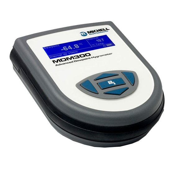
Page 10: Figure 1 Mdm300 Advanced Dew-Point Hygrometer
MDM300 User’s Manual INTRODUCTION Two versions of the instrument are available, an MDM300 (standard) version and an MDM300 (intrinsically safe) version. This manual covers the MDM300 version only. For information about the MDM300 I.S. contact your local Michell Instruments’ representative (contact information at www.michell.com). -
Page 11: Controls And Indicators
MDM300 User’s Manual INTRODUCTION Controls and Indicators The controls and indicators associated with the MDM300 instrument are located on the front panel of the instrument. Connections to the MDM300 dew-point hygrometer, comprising the gas ports, battery charger input connector and input connector for the external sensor are all made to the top panel. -
Page 12: Table 1 Controls And Indicators
MDM300 User’s Manual INTRODUCTION Item Panel Description Function keys. Refer to Section 1.2 for the details of these Front keys. Instrument display, partitioned to show 3 main panels: The primary display shows internal sensor parameters. The secondary display indicates the external sensor Front parameter. -
Page 13: Function Keys
MDM300 User’s Manual INTRODUCTION Function Keys The function keys, located on the front panel, are used to select operations from the menus and to select and enter parameter variables within those menu levels. The function key described is shaded darker and the operation of the keys is as follows: 1.2.1... -
Page 14: Instrument Display
MDM300 User’s Manual INTRODUCTION Instrument Display The graphics display and the associated function keypad ( Figure 2), form the operator interface of the equipment. Figure 3 shows all the elements of a typical display page after the instrument’s initialization period has completed. -
Page 15: Display Units
MDM300 User’s Manual INTRODUCTION 1.3.1 Display Units The instrument can display the measured reading in the following units: Absolute Humidity • Moisture Content • ppmV • ppmW (AIR, USER, H , SF , CO or N Dew point • °C •... -
Page 16: Status Display Indications
MDM300 User’s Manual INTRODUCTION 1.3.2 Status Display Indications ‘ Initializing Internal Sensor’ This is displayed immediately after the instrument has been powered up, and indicates that the sensor is being heated up to accelerate equilibrium with the moisture in the sample gas. -
Page 17: Installation
It is essential that the installation of the electrical and gas supplies to this instrument be undertaken by qualifi ed personnel. Unpacking the Instrument The MDM300 instrument is packed into a standard box and the method of unpacking is shown below: Figure 4 Packing Method Open the box (1) and unpack carefully. -
Page 18: Mdm300 Accessories
INSTALLATION MDM300 Accessories The accessories for the MDM300 are shown in Figure 6 . Items 1 to 7 are supplied as standard and item 8 is optional. Please check that all the standard components are present after unpacking. Report any shortages immediately. -
Page 19: Figure 6 Accessories
MDM300 User’s Manual INSTALLATION MDM300 & MDM300 I.S. Quick Start Guide Connect the MDM to the sample gas stream Determine the approximate Typical MDM300 Sampling Arrangement dew point by using the ‘initial check’ procedure on the reverse SAMPLE FLOW Is the... -
Page 20: Operational Requirements
Figure 5 . The MDM300 is supplied with a large bore orifi ce fi tting installed into the Gas In and Gas Out ports. These fi ttings have an 1/8” NPT female thread to allow the user to connect other components of their choice. -
Page 21: Gas Inlet /Outlet Fittings
Michell Instruments, on request. NOTE: The bonded seals used for the MDM300 are Dowty part number 400- 228-4490-74 (available from Michell instruments, part number MDM300-DS). -
Page 22: Connect External Transmitters
Connect External Transmitters Dew point, pressure and temperature sensors and connecting cable can be ordered from Michell Instruments or a local representative. The connector and cable can be ordered separately to allow connection to any 4-20 mA loop powered sensor. -
Page 23: Set-Up External Temperature Transmitter Parameters
MDM300 User’s Manual INSTALLATION 2.6.2 Set-Up External Temperature Transmitter Parameters After adding a temperature transmitter, the following parameters must be defi ned. Switch on the instrument and initially set the required units to either DP/TEMP °C, °F from the Settings Menu (refer to Section 3.4.1). -
Page 24: Entering User Pressure
2.6.4 Entering User Pressure The MDM300 can be programmed with a pressure to be used in the calculation of atmospheric equivalent or pressure dew point, moisture content or absolute humidity. NOTE: Care should be taken to ensure that the entered pressure is correct as it may have a considerable effect on the measurement. -
Page 25: Battery Charging
Figure 14 Battery Charger Connection Connect an AC power supply, 90 to 264 V AC, 50/60 Hz, to the battery charger unit. NOTE: The MDM300 instrument does not need to be switched on in order to charge the battery. Michell Instruments... - Page 26 If the battery has been damaged then the charger will not begin the fast-charge stage. Please contact Michell Instruments’ service department for advice. Once the charger has fi nished the fast-charge stage it can be safely disconnected. Switch off the AC power supply, remove the charger unit and close the instrument’s charge connector protection cover.
-
Page 27: Operation
MDM300 User’s Manual OPERATION OPERATION High pressure gases are potentially hazardous. Energy stored in these gases can be released suddenly and with extreme force. High pressure systems should be assembled and operated only by people who have been trained in proper safety practices. -
Page 28: Instrument Start-Up
MDM300 User’s Manual OPERATION Instrument Start-Up At switch on, the instrument goes through an initialization process lasting several minutes. During MDM300 this time the internal sensor is heated to a maximum System Initializing of +70°C (+158°F). The heating process increases... -
Page 29: Overall Menu Structure And Operation
MDM300 User’s Manual OPERATION Overall Menu Structure and Operation 3.3.1 SET-UP Menu All instrument settings are made from the SET-UP Menu which is accessible from the Main Display by pressing the key. Enter On the fi rst occasion after switch-on the Passcode Entry page will be displayed. Enter... -
Page 30: Figure 16 Menu Structure
MDM300 User’s Manual OPERATION Scroll Unit Files Page to view Main Display (Primary, Chart page Secondary and Status (only if internal sensor LOGGING? Windows) available) Logs Page PASSCODE FOR SETUP (on start-up only) =7316 Scroll to Adjust Digit Chart Reset Page... -
Page 31: Set-Up Menu Parameters
MDM300 User’s Manual OPERATION SET-UP Menu Parameters Follow the instructions in Section 3.3.1 to select the required parameters. 3.4.1 SETTINGS PRIMARY DP AT ATMOS SETTINGS DP/TEMP UNIT °C PRESSURE UNIT Psig GAS TYPE MOL WEIGHT CHART INTERVAL Figure 17 SETTINGS Page... -
Page 32: Logging
MDM300 User’s Manual OPERATION 3.4.2 LOGGING The LOGGING Set-Up Menu can be accessed by pressing the key three times from the Main Display. It can also be accessed through the SET-UP Menu. > FILE NAME LOGGING PARAMETER DEWP LOG INTERVAL... -
Page 33: Bluetooth
3.4.3 BLUETOOTH Bluetooth mode is used, in conjunction with a dedicated MDM300 application software package, for the purpose of uploading datalog fi les to a PC using a wireless connection. Within the PC the dedicated Michell application software package is used to upload the fi les to the PC’s desktop, from where they can be loaded into other programs, e.g. -
Page 34: 3.4.3.1 Bluetooth Pairing Procedure
MDM300. Double click the instrument icon and enter the instrument’s pairing passcode ( ) for all MDM300 instruments. NOTE: Each digit will 7316 be shown only briefl y as it is entered and then hidden. When all digits have been entered click... -
Page 35: External (Sensor Interface)
MDM300 User’s Manual OPERATION 3.4.4 EXTERNAL (Sensor Interface) For more information refer to Section 2.6. EXTERNAL TYPE NONE EXTERNAL EXTERNAL ZERO EXTERNAL SPAN USER PRESSURE Psig Figure 21 EXTERNAL SET-UP Page Parameter Description Defi nes the type of connected external transmitter. -
Page 36: Clock
MDM300 User’s Manual OPERATION 3.4.5 CLOCK YEAR CLOCK MONTH HOUR Figure 22 CLOCK Page Parameter Description Current year YEAR Available Input: Range: 00 to 99 Current month MONTH Available Input: Range: 01 to 12 Current day Available Input: Range: 01 to 31... -
Page 37: Hmi
MDM300 User’s Manual OPERATION 3.4.6 CONTRAST BRIGHTNESS KEY TONE BL TIMEOUT LANGUAGE PRIMARY DISP INTERN Figure 23 HMI Page Parameter Description Sets the contrast on the screen. CONTRAST Available Input: Range: in 5% increments 0 to 100% Sets the brightness of the screen. -
Page 38: Info
MDM300 User’s Manual OPERATION 3.4.7 INFO MDM300 Portable Hygrometer Firmware 36171 Ver 10.10 Sensor serial number B585-006 Sensor next cal due 26/03/09 Sensor hours used 371 hr www.michell.com Figure 24 INFO Page This page contains system information and no changes can be made. -
Page 39: Log Files Page
Figure 26 LOG FILES Page The content of the datalog fi les cannot be examined but, by enabling the instrument’s Bluetooth mode, (see Section 3.4.3), the MDM300 application software may be used to upload the datalog fi les to a PC. -
Page 40: 3.4.11 Calibration
MDM300 User’s Manual OPERATION The display shows: Indicates a log number for each set of log points Value of primary display parameter Value of secondary display parameter Status column which reports the status of the instrument at each log point in hexadecimal code. -
Page 41: Default Parameters
Section 3.4.5, Figure 21 Current UK time & date CONTRAST BRIGHTNESS Section 3.4.6, Figure 22 KEYTONE BL TIME-OUT 15 sec LANGUAGE PRIMARY DISP INTERN CALIBRATION & INFO Section 3.4.11 & Section 6 Default values not applicable Table 10 MDM300 Default Parameters Michell Instruments... -
Page 42: Guide To Measurement And Sampling
MDM300 User’s Manual OPERATION Guide to Measurement and Sampling Operating the MDM300 is very straightforward, but sampling conditions can vary greatly from one application to another. To get the best possible response speed, the appropriate procedure should be followed. HIGH PRESSURE! High pressure gases are potentially hazardous. -
Page 43: Measuring At Atmospheric Or System Pressure
MDM300 User’s Manual OPERATION It is highly recommended that a fi lter is installed upstream of the MDM300. Refer to the Sample Conditioning section of the Sampling Hints found in Section 4.1. 3.6.1 Measuring at Atmospheric or System Pressure Without a metering valve The large and small orifi... -
Page 44: Measurement Guide
Table 11 MDM300 Measurement Procedures Standard Purge (Atmospheric Measurement) Connect the MDM300 to the sample gas stream. Adjust the fl ow rate, using the inlet fl ow control valve, to between 0.2 to 1.2 Nl/min (0.5 to 2.5 scfh). The outlet fl ow control valve should be fully open. - Page 45 OPERATION Standard Purge (Pressure Measurement) Connect the MDM300 to the sample gas stream. Adjust the fl ow rate, using the outlet fl ow control valve, to between 0.2 to 1.2 Nl/min (0.5 to 2.5 scfh). The inlet fl ow control valve should be fully open.
-
Page 46: Conditional Sensor Purge
15 seconds or the battery may be damaged. NOTE: Michell Instruments will replace the older FW 7219 charger with the new Cell Con model free of charge. The Cell Con will re-charge batteries which have completely discharged. -
Page 47: Good Measurement Practice
GOOD MEASUREMENT PRACTICE GOOD MEASUREMENT PRACTICE The MDM300 is designed to operate in a fl owing gas stream with fl ow rates between 0.2 and 1.2 Nl/min (0.5 and 2.5 scfh). Flow regulation is provided with the MDM300 instrument between 2.5 and 10 barg. Outside of this, the sample fl ow must be regulated outside the unit. -
Page 48: Sampling Hints
MDM300 User’s Manual GOOD MEASUREMENT PRACTICE Sampling Hints Measurement of moisture content is a complex subject, but does not need to be diffi cult. This section aims to explain the common mistakes made in measurement situations, the causes of the problem, and how to avoid them. Mistakes and bad practices can cause the measurement to vary from the expectation;... - Page 49 MDM300 User’s Manual GOOD MEASUREMENT PRACTICE Sample Tubing Length The sample point should always be as close to the critical measurement point as possible, in order to obtain a truly representative measurement. The length of the sample line to the sensor or instrument should be as short as possible. Interconnection points and valves trap moisture, so using the simplest sampling arrangement possible will reduce the time it takes for the sample system to dry out when purged with dry gas.
- Page 50 Before disconnecting the MDM300 from the gas line it is essential to vent the system to atmospheric pressure, otherwise severe injury could result.
-
Page 51: Application Software
fi le on the CD. The following authorization code will be required during the installation process: MDM-300-7392 Once the software has been installed and run, the MDM300 can be linked to the PC by activating the Bluetooth on the MDM300 and then connecting with the application software (see Section 3.4.3 for details). -
Page 52: Calibration
If these facilities do not exist it is recommended that the instrument be returned to the manufacturer, Michell Instruments Ltd., or one of the approved agents. A calibration certifi cate bearing a seven point calibration is issued with each instrument. -
Page 53: Calibration Method
Ensure that all sample tubing and connectors are made from stainless steel and are of suitable quality. Connect the MDM300 to a dew-point generator and establish a gas fl ow through the instrument. Apply a dew point of -100°C and allow the instrument’s reading to stabilize for a minimum of 96 hours (including dry down). -
Page 54: Calibration Correction Method
Entry to the CALIBRATION Menu is protected by a passcode ( 4876 If the MDM300 has been confi gured for use with an external Easidew transmitter the following page will be shown, once the passcode has been successfully entered. Select calibration... -
Page 55: Easidew Offset Adjustment
C dp Offset -1.3° C dp between the readings of the MDM300 and the external transmitter as shown in Figure 34 . Press the key to apply the offset. Press to confirm or press to exit Confi rm the operation by pressing the key or, MDM300 6.6°... -
Page 56: Easidew One Point Adjustment
Easidew Offset Adjustment and connect to a dew-point generator. Easidew One Point Adjustment Apply a dew-point reference to the MDM300 and external transmitter at the required dew point (-20.6°C) *Communicating with Easidew* in this example. -
Page 57: Shipping
Create a packing list detailing all equipment contained in the box, place it inside the box and seal the box. Before disconnecting the MDM300 from the gas line it is essential to vent the system to atmospheric pressure, otherwise severe injury could result. - Page 58 MDM300 User’s Manual APPENDIX A Appendix A Technical Specifi cations 97122 Issue 16, October 2017...
-
Page 59: Appendix A Technical Specifi Cations
MDM300 User’s Manual APPENDIX A Appendix A Technical Specifi cations Performance Measurement Technology Michell ceramic sensor ±1°C from -60 to +20°Cdp (-76 to +68°Fdp) Accuracy ±2°C from -100 to -60°Cdp (-148 to -76°Fdp) ±0.2°C (0.3°F) temperature For Spot Checks -70 to +20°Cdp (-95 to +68°Fdp) -
Page 60: Dimensions
MDM300 User’s Manual APPENDIX A Dimensions Figure 38 Dimensions 97122 Issue 16, October 2017... - Page 61 MDM300 User’s Manual APPENDIX B Appendix B Datalog Status Display Michell Instruments...
-
Page 62: Appendix B Datalog Status Display
Figure 39 . Bit 1 is the least signifi cant bit. The four most signifi cant bits 13 to 16 are for Michell Instruments’ service use and so the fi rst character in any MDM300 ST display will always read 0. -
Page 63: Table 13 Status Register Flags
MDM300 User’s Manual APPENDIX B Table 13 shows the status fl ags associated with each bit of the status register. If a status fl ag is set high then the associated condition exists. If it is set low, then that condition does not exist. -
Page 64: Issue 16, October
MDM300 User’s Manual APPENDIX C Appendix C FCC Declaration 97122 Issue 16, October 2017... -
Page 65: Appendix Cfcc Declaration
APPENDIX C Appendix C FCC Declaration MDM300 Advanced Dewpoint Hygrometer. This Device complies with FCC Rules Part 15 Subpart B Unintentional Radiators Class B digital devices. Operation is subject to the following conditions: 1) This device may not cause harmful interference 2) This device must accept any interference received, including interference that may cause undesired operation. - Page 66 MDM300 User’s Manual APPENDIX D Appendix D Quality, Recycling & Warranty Information 97122 Issue 16, October 2017...
-
Page 67: Appendix D Quality, Recycling, Compliance & Warranty Information
APPENDIX D Appendix D Quality, Recycling, Compliance & Warranty Information Michell Instruments is dedicated to complying to all relevant legislation and directives. Full information can be found on our website at: www.michell.com/compliance This page contains information on the following directives: •... - Page 68 MDM300 User’s Manual APPENDIX E Appendix E Return Document & Decontamination Declaration 97122 Issue 16, October 2017...
-
Page 69: Appendix E Return Document & Decontamination Declaration
Has the equipment been cleaned and decontaminated? NOT NECESSARY Michell Instruments will not accept instruments that have been exposed to toxins, radio-activity or bio-hazardous Work will not be carried out on any unit that does not have a completed decontamination declaration. - Page 72 http://www.michell.com...
Need help?
Do you have a question about the MDM300 and is the answer not in the manual?
Questions and answers