Table of Contents
Advertisement
Optidew & Optidew Vision
High Performance Optical
Dew-Point Transmitter
User's Manual
s
a t u
S t
u r e
O u
r a t
n
r O
p e
e
w e
T e m
o b
P r
P o
t
z
p u
0 H
r In
-4 4
w e
P o
4 7
a c
4 V
-2 5
8 5
r t
P o
n s
t io
ic a
t
o in
u n
w p
m m
o r
D e
C o
n s
S e
n s
c t io
n e
o n
t C
t p u
97430 Issue 2
March 2017
Advertisement
Table of Contents

Related Manuals for Michell Instruments Optidew


Summary of Contents for Michell Instruments Optidew
- Page 1 Optidew & Optidew Vision High Performance Optical Dew-Point Transmitter User’s Manual t io ic a o in a t u c t io t p u u r e r a t T e m r In -4 4 -2 5...
- Page 2 Please fi ll out the form(s) below for each instrument that has been purchased. Use this information when contacting Michell Instruments for service purposes. Instrument Code Serial Number Invoice Date Location of Instrument Tag No Instrument Code Serial Number Invoice Date...
- Page 3 © 2016 Michell Instruments This document is the property of Michell Instruments Ltd. and may not be copied or otherwise reproduced, communicated in any way to third parties, nor stored in any Data Processing System without the express written authorization of Michell Instruments Ltd.
-
Page 4: Table Of Contents
Optidew Series User’s Manual Contents Safety ..........................vi Electrical Safety ......................vi Pressure Safety ......................vi Toxic Materials ......................vi Repair and Maintenance ....................vi Calibration ........................vi Safety Conformity ......................vi Abbreviations ........................vii Warnings ........................... vii INTRODUCTION ....................1 Optidew Series ....................2 Optidew Sensor ....................3 INSTALLATION ....................4... - Page 5 Table 2 Sensor Body Materials .................3 Appendices Appendix A Technical Specifi cation ................34 Appendix B Optidew RS232 Commands ................ 37 Appendix C Troubleshooting - Common Faults ............... 41 Appendix D Dimensional Drawings................47 Optidew ..................47 Optidew Integral Version .............. 48 Optidew Vision ................
-
Page 6: Safety
Michell Instruments’ worldwide offi ces contact information. Calibration The recommended calibration interval for the Optidew Series is one year, unless otherwise specifi ed by Michell Instruments. The instrument should be returned to the manufacturer, Michell Instruments, or one of their accredited service agents for re-calibration. -
Page 7: Abbreviations
Optidew Series User’s Manual Abbreviations The following abbreviations are used in this manual: alternating current water activity - relative humidity on a scale of 0-1 with no units pressure unit (atmosphere) barg pressure unit (=100 kP or 0.987 atm) gauge ºC... -
Page 8: Introduction
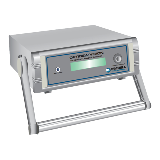
Compact and Convenient Package The bench-top enclosure for the Optidew Vision has a handle that doubles as a stand. An optional panel-mounting kit is also available for 19” rack mounting. A bright and clear 2-line vacuum fl uorescent display on the front panel enables the instrument parameters to be monitored even when not connected to the application software. -
Page 9: Optidew Series
Optidew Series User’s Manual INTRODUCTION Optidew Series The Optidew Series is available in two variants, which differ only in enclosure type, connectors and sensor cable: Optidew Optidew Vision Figure 1 Figure 2 The Optidew features a rugged 304 stainless steel industrial enclosure, offering protection to IP66 / NEMA 4x. -
Page 10: Optidew Sensor
Optidew Series User’s Manual INTRODUCTION Optidew Sensor Optidew Series’ sensors are available with either single stage, or dual stage peltier devices, and with a variety of different sensor body and mirror materials. The following tables show the capabilities of each sensor type:... -
Page 11: Installation
Mounting Optidew The Optidew can be wall mounted using the four drilled tabs on each corner. It is possible to install the Optidew outside, providing it is shielded from direct sunlight and the climate is within the environmental requirements listed in Appendix A, Technical Specifi... - Page 12 Refer to Section 5 for more details. Serial Connector For digital serial communications. Refer to Section 2.4. Sensor Connector Used for connecting the Optidew sensor via the sensor cable. Mounting Point For integral sensor version. Power Connector Universal power input 90 to 264 V AC OR 127 to 370 V DC, 47 to 440 Hz Temperature Connector For connection of remote PT100 temperature probe.
-
Page 13: Optidew Vision
Optidew Series User’s Manual INSTALLATION 2.2.1 Optidew Vision Front Panel Number Description Status LED Lit to indicate instrument is in DCC or DATA HOLD mode. Flashes in the event of an Optics fault. This normally means the mirror needs cleaning, followed by resetting the mirror condition during a DCC cycle. - Page 14 For digital serial communications. Refer to Section 2.4. Temperature Connector For connection of remote PT100 temperature probe. Sensor Connector Used for connecting the Optidew sensor via the sensor cable. Output Connector Two current outputs, and two relay connections. Refer to Section 2.3. 97430 Issue 2, March 2017...
-
Page 15: Electrical Power Connections
The part number for a replacement power cable is OPT-POWER-CAB-2. Optidew Vision The Optidew Vision is supplied with a 2m (6.5ft) IEC cable. The IEC socket on the back of the instrument features an integrated ON/OFF switch and fuse holder that accepts a 2A, Quick blow, Glass, 20 x 5mm fuse. -
Page 16: Analog Outputs
Optidew Series User’s Manual INSTALLATION 2.3.1 Analog Outputs The analog output connector is located on the front panel of the Optidew, and on the rear panel of the Optidew Vision. The electrical connections are shown below: Optidew Optidew Vision 15-Way D Connector... -
Page 17: Relay Outputs
DCC cycle. Refer to Section 5 for more details. Refer to Section 2.3 for wiring details. Digital Communications Port The Optidew Series provides either RS232 or RS485 serial communications via a 9 way D-type connector. This allows for communication with a PC, data logger, or other hardware device. -
Page 18: Sensor Installation
Optidew Series User’s Manual INSTALLATION Sensor Installation The dew-point sensor contains the optical system and the chilled mirror. It is fi tted with a bayonet connector to allow easy and secure connection to the instrument using the supplied sensor cable. -
Page 19: Integral Sensor Confi Guration
2.5.1 Integral Sensor Confi guration The Optidew sensor can be fi tted directly to the bayonet-type connector on the case of the instrument without using a sensor cable. A retaining bracket provides support for the sensor. NOTE: This is not possible with the Optidew Vision. -
Page 20: Operation
The Optidew is available with an optional VFD (Vacuum Fluorescent Display) fi tted on the top panel of the instrument. The Optidew Vision features a front panel VFD. When power is applied to the Optidew or Optidew Vision the display will momentarily show test characters, after which the start-up banner will be displayed for approximately 7 seconds. -
Page 21: Screens
Screen 1: Displays the status of the Optidew It will show DCC, DATA HOLD, OPTICS ALARM or MEASURE according to the current status of the Optidew instrument Screen 2: Peltier Power and the Mirror Condition Refer to Section 3.3.7... -
Page 22: Operational Functions
Optidew Series User’s Manual OPERATION Operational Functions 3.3.1 Operating Principle The system operates on the chilled mirror principle, whereby a gas sample is passed over the surface of a polished mirror contained within the open sensor housing. At a temperature dependent upon the moisture content in the gas, and the operating pressure, the moisture in the gas condenses out on the surface of the mirror. -
Page 23: Dcc
The instrument will be in DATA HOLD mode until the instrument has settled on the dew point and the measurement is stable. For more information about the operating cycle of the Optidew, and DATA HOLD mode refer to Sections 3.4.2 and 3.4.4. -
Page 24: Maxcool
– once ice has formed it will remain as ice until the temperature is raised above 0°C (+32°F). FAST can only be enabled or disabled by sending the appropriate command to the Optidew via the digital communications port. Refer to Appendix B for a complete list of instrument commands. 97430 Issue 2, March 2017... -
Page 25: Mirror Condition And Peltier Power
Optics fault occurs. Refer to Section 5 for further instructions. Optisoft Application Software The Opti-Soft application software is an interface to the Optidew Series that provides a display of the measured and calculated parameters, system status, charting and logging, statistical information and a facility to view and change the system parameters. -
Page 26: Virtual Hygrometer Window
Optidew Series User’s Manual OPERATION 3.4.1 Virtual Hygrometer Window Virtual Hygrometer Window Figure 5 The Humidity Display has the ability to show dew point (°C/°F), %RH, gm , gkg , ∆ (t – tdp) or a by clicking on the button. -
Page 27: Instrument Status
Optidew Series User’s Manual OPERATION 3.4.3 Instrument Status Instrument status is shown on the fi ve colored indicators. Status Indicator Description In DCC (initiated automatically or by using the DCC Initiate button), both the DCC and HOLD indicators will illuminate showing the DCC status and the hold on Channel 1 mA output. -
Page 28: Parameter Setup
Optidew Series User’s Manual OPERATION 3.4.4 Parameter Setup The Parameter Setup window allows the setting and ranging of Channel 1 and 2 mA outputs, the duration for DCC, HOLD, and Measurement, and the values for atmospheric pressure and alarm set points. -
Page 29: Charting And Logging
Optidew Series User’s Manual OPERATION 3.4.5 Charting and Logging Clicking on the button in the Virtual Hygrometer window brings up the Chart Chart/log / log control panel window. Chart/Log Control Panel Window Figure 7 The chart, in its default confi guration, displays dew point, temperature and % RH. -
Page 30: Statistics
Optidew Series User’s Manual OPERATION Chart Window Figure 8 3.4.6 Statistics Clicking on the button on the Virtual Hygrometer window will display the Statistics Basic statistics window as shown below: This window shows the maximum, minimum and average of each parameter since the... -
Page 31: Control Parameters
3.4.8 Calibration Correction Every Optidew is delivered with a Calibration Certifi cate detailing the deviation at each measurement point from a known reference value. Data provided on the Calibration Certifi cate is normally arranged as shown in the following extracts: Extract from a UKAS Calibration Certifi... - Page 32 Figure 11 shows the Calibration Correction window. Four sets of data may be entered: Dew-point data for the reference hygrometer (sometimes DP Ref called the actual dew point or the standard) Measured dew-point value of the Optidew under test DP Reading Temperature data from the reference thermometer Temp Ref...
-
Page 33: Change Of Password
Optidew Series User’s Manual OPERATION Once all necessary data has been entered in the Calibration Correction window, click on the check box and then click Use Calibration Date to Correct Measure Values to return to the main Virtual Hygrometer display. Upon the next... -
Page 34: Good Measurement Practice
Optidew Series User’s Manual OPERATION GOOD MEASUREMENT PRACTICE Sampling Hints Measurement of moisture content is a complex subject, but does not need to be diffi cult. This section aims to explain the common mistakes made in measurement situations, the causes of the problem, and how to avoid them. Mistakes and bad practices can cause the measurement to vary from the expectation;... - Page 35 Optidew Series User’s Manual GOOD MEASUREMENT PRACTICE Adsorption and Desorption Adsorption is the adhesion of atoms, ions, or molecules from a gas, liquid, or dissolved solid to the surface of a material, creating a fi lm. The rate of adsorption is increased at higher pressures and lower temperatures.
- Page 36 Optidew Series User’s Manual GOOD MEASUREMENT PRACTICE Condensation and Leaks Dewpoint > T Dewpoint < T Maintaining the temperature of the sample system tubing above the dew point of the sample is vital to prevent condensation. Any condensation invalidates the sampling process as it changes the water vapor content of the gas being measured.
- Page 37 Optidew Series User’s Manual GOOD MEASUREMENT PRACTICE An excessively high fl ow rate can: • Introduce back pressure, causing slower response times and unpredictable effects on equipment such as humidity generators. • Result in a reduction in depression capabilities in chilled mirror instruments by having a cooling effect on the mirror.
-
Page 38: Maintenance
Optidew Series User’s Manual GOOD MEASUREMENT PRACTICE MAINTENANCE Failure to follow these maintenance procedures may result in premature wear or damage to the heat pump. Sensor Mirror Cleaning Throughout the life of the instrument, periodic cleaning of the mirror surface and optics window may be required. - Page 39 Potentiometer Optidew Optidew Vision Procedure (Optidew Series with display, or using application software) NOTE: The instructions on the next page can be followed for adjustment using RS232/RS485 serial commands, if more convenient. Clean the mirror according to the instructions above.
- Page 40 Optidew Series User’s Manual MAINTENANCE Procedure (using RS232/RS485 serial commands) Connect to the instrument using the RS232/RS485 connection. Send the following commands, one after the other: Command Description Stops all continuous output to the serial port Continuously outputs signal mirror level, between 0 and...
- Page 41 Optidew Series User’s Manual MAINTENANCE Appendix A Technical Specifi cations Michell Instruments...
-
Page 42: Appendix A Technical Specifi Cation
Optidew Series User’s Manual APPENDIX A Appendix A Technical Specifi cation Performance Measurement ±0.2°Cdp (±0.36°Fdp), ±0.15°Cdp (±0.27°Fdp) accuracy optional, ±0.1°C Accuracy* (±0.18°F) temperature Measurement °C, °F dew point; %RH; °C, °F temperature; g/m ; g/kg; a ; Δ (t – t dew point) Units Response Speed 1°C per second (1.8°F per second) plus settling time (dew point dependant) - Page 43 Conditions Optidew (only): 100% RH condensing with optional weatherproof cable pack Optidew: 304 stainless steel (DIN 1.4301) Enclosure Optidew Vision: Standing case with carry handle / Panel mounting kit optional Optidew: IP66 (NEMA 4X) Ingress Protection Optidew Vision: IP54 (NEMA 2) rated...
-
Page 44: Appendix B Optidew Rs232 Commands
Optidew Series User’s Manual APPENDIX A Appendix B Optidew RS232 Commands 97430 Issue 2, March 2017... - Page 45 • disables FAST function fastoff • sets unit for CMDT mode (temperature measurement disabled) cmdt • sets unit for OPTIDEW (temperature measurement enabled) opti Measured and calculated parameters: • returns dew point value • returns temperature value • returns %rh value •...
- Page 46 Optidew Series User’s Manual APPENDIX B Current outputs: • sets output1 minimum, where X = an integer between -200 & 200 opl=X • sets output1 maximum, where X = an integer between -200 & 200 oph=X • sets current output1 to indicate DEWPOINT outdp •...
- Page 47 0 to 1023. In this example the value is 0589, or 24% (cooling). NOTE: The depression is shown on the Optidew/Optidew Vision display and OptiSoft as a percentage, and is calculated as follows: If depression > 450 peltier drive % = (PeltierDrive - 450) / 5.73, peltier is cooling...
-
Page 48: Appendix C Troubleshooting - Common Faults
Optidew Series User’s Manual APPENDIX B Appendix C Troubleshooting Common Faults 97430 Issue 2, March 2017... - Page 49 This will invalidate the calibration and may cause permanent damage to the instrument, voiding the warranty. It is permitted to remove the lid of the Optidew for the purpose of adjusting the mirror condition potentiometer only. The Optidew Vision must NOT be disassembled.
- Page 50 Ensure continuity of sensor cable conductors i.e. Pin A – Pin A continuity Ensure sensor cable connections are sound Resolution Source replacement sensor cable from local Michell Instruments representative Cause Sensor PRT damaged – open or short circuit Try another sensor Diagnosis Measure resistance between sensor pins A &...
- Page 51 Try another sensor cable Diagnosis Ensure continuity of sensor cable conductors i.e. Pin A – Pin A continuity Ensure sensor cable connections are sound Resolution Source replacement sensor cable from local Michell Instruments’ representative Cause No light detected (photo detector fault) Diagnosis Ensure LED is illuminated while instrument is switched on Resolution Contact Michell Instruments’...
- Page 52 Diagnosis Ensure continuity of sensor cable conductors i.e. Pin A – Pin A continuity Ensure sensor cable connections are sound Resolution Source replacement sensor cable from local Michell Instruments’ representative Cause Dew point below measurement capability of sensor Check maximum depression from ambient temperature of 20°C meets...
- Page 53 Optidew Series User’s Manual APPENDIX C Symptom: Dew-point reading in error If dew point < 0°C then error may be due to Optidew Cause measuring super-cooled water on the mirror instead of ice. Error will be approximately 10% of reading...
-
Page 54: Appendix D Dimensional Drawings
Optidew Series User’s Manual APPENDIX D Appendix D Dimensional Drawings 97430 Issue 2, March 2017... -
Page 55: Optidew
Optidew Series User’s Manual APPENDIX D Appendix D Dimensional Drawings Optidew Wall Mounting Brackets - 4 each Ø M8 OPTIDEW High Performance Optical Dew-point Transmitter 222mm (8.74”) 200mm (7.87”) Michell Instruments... -
Page 56: Optidew Integral Version
Optidew Series User’s Manual APPENDIX D Optidew Integral Version 222mm (8.74”) Wall Mounting Brackets 4 each Ø M8 OPTIDEW High Performance Optical Dew-point Transmitter Bracket Retaining 200mm (7.87”) 97430 Issue 2, March 2017... -
Page 57: Optidew Vision
Optidew Series User’s Manual APPENDIX D Optidew Vision 250mm (9.8”) 130mm (5.1”) 290mm (11.4”) OVERALL WIDTH OPTIDEW VISION Precision Dewpointmeter Alarm/Dcc Display Control Michell Instruments... -
Page 58: Sensor And Probe Dimensions
Optidew Series User’s Manual APPENDIX D Sensor and Probe Dimensions 74mm (2.91”) 2.91 With Sintered or HDPE Guard With Sintered or HDPE Guard (Optional) (Optional) 3.5mm (0.14”) 0.14 Dowty Bonded Seal Dowty Bonded Seal M36X1.5-6g M36X1.5-6g Ø28mm Ø45mm Ø1.10 (1.10”) Ø1.77... -
Page 59: Appendix E Quality, Recycling & Warranty Information
APPENDIX E Optidew Series User’s Manual Appendix E Quality, Recycling & Warranty Information Michell Instruments... - Page 60 Optidew Series User’s Manual APPENDIX E Appendix E Quality, Recycling & Warranty Information Michell Instruments is dedicated to complying to all relevant legislation and directives. Full information can be found on our website at: www.michell.com/compliance This page contains information on the following directives: •...
-
Page 61: Appendix F Return Document & Decontamination Declaration
Optidew Series User’s Manual APPENDIX F Appendix F Return Document & Decontamination Declaration Michell Instruments... - Page 62 Has the equipment been cleaned and decontaminated? NOT NECESSARY Michell Instruments will not accept instruments that have been exposed to toxins, radio-activity or bio-hazardous Work will not be carried out on any unit that does not have a completed decontamination declaration.
- Page 63 NOTES:...
- Page 66 http://www.michell.com...
Need help?
Do you have a question about the Optidew and is the answer not in the manual?
Questions and answers