Table of Contents
Advertisement
Advertisement
Table of Contents

Related Manuals for Siemens SICHARGE CC AC22-MID


Summary of Contents for Siemens SICHARGE CC AC22-MID
- Page 2 Introduction Safety information SICHARGE Description Mounting/assembly SICHARGE CC AC22 - MID SICHARGE Operating Instructions Connection and commissioning Operation Operating Instructions Faults Maintenance and service Adhesive surfaces Service & Support Disposal Technical specifications Appendix List of abbreviations 07/2020 A5E48573001-AB...
- Page 3 Note the following: WARNING Siemens products may only be used for the applications described in the catalog and in the relevant technical documentation. If products and components from other manufacturers are used, these must be recommended or approved by Siemens. Proper transport, storage, installation, assembly, commissioning, operation and maintenance are required to ensure that the products operate safely and without any problems.
-
Page 4: Table Of Contents
Table of contents Introduction ............................5 Purpose of this documentation .................... 5 Conventions ........................5 Open-source software ......................6 Safety information ..........................7 General safety information ....................7 Safe installation and assembly ................... 10 Safety during electrical installation ..................12 Safety during operation ..................... - Page 5 Diagnostic tests ......................... 89 Software updates ......................89 Adhesive surfaces ..........................90 Adhesive surfaces ......................90 Service & Support ..........................92 10.1 Siemens Industry Support ....................92 Disposal ............................... 93 11.1 Recycling and disposal ....................... 93 Technical specifications ........................94 12.1 Technical specifications .....................
-
Page 6: Introduction
Introduction Purpose of this documentation These operating instructions contain the information required for installing, commissioning, and operating the SICHARGE CC AC22 charging station. The operating instructions contain information on proper use of the charging station. WARNING Failure to comply with the information in these operating instructions may result in the following: •... -
Page 7: Open-Source Software
Siemens accepts no liability for the use of the open-source software over and above the intended program sequence, or for any faults caused by modifications to the software. -
Page 8: Safety Information
Safety information General safety information This section contains important, generally valid information on: • Avoiding accidents or damage to property • Application planning • Mounting and installation • Operation • Maintenance and cleaning of the charging station Read this section carefully and follow the safety regulations. This will minimize safety risks. Make your staff and customers aware of this section. - Page 9 Safety information 2.1 General safety information Target group The sequence of the following safety instructions is based on the use stages of the product life cycle. The description is addressed to the following groups of people: • The operator responsible for the safe operation of the device •...
- Page 10 Safety information 2.1 General safety information Qualified personnel All activities must be performed by qualified personnel. Due to their qualifications, experience, and training, these people have knowledge of: • Relevant standards and regulations • Accident prevention regulations They are authorized to perform the necessary activities and to detect and prevent possible dangers.
-
Page 11: Safe Installation And Assembly
Safety information 2.2 Safe installation and assembly Cleaning Protect the environment and use biodegradable cleaning agents to clean surfaces. Clean surfaces of the charging station using a damp cloth. Do not use steam jets or water jets for cleaning, as they may cause moisture or water to infiltrate the charging station. - Page 12 Safety information 2.2 Safe installation and assembly Electrical cables There is a risk of electric shock due to exposed electrical connections and components. Before starting the installation work, check that the supply cable has been disconnected from the mains and secured against restart. If damage or tampering is visible, do not commission the charging station.
-
Page 13: Safety During Electrical Installation
Safety information 2.3 Safety during electrical installation Safety during electrical installation Observe the following points for the electrical installation. The electrical connection of the charging station can only be performed by skilled electricians and can only be carried out at zero current. - Page 14 Safety information 2.3 Safety during electrical installation Damage to sockets and charging cable Inspect sockets and the charging cable for damage on a regular basis. Damaged charging cables endanger safe operation. If you detect damage to the charging cable, do not commission the cable or stop a running charging process.
-
Page 15: Safety During Operation
Safety information 2.4 Safety during operation Safety during operation Observe the following points when operating the charging station, as well as the applicable regional standards and regulations. Failure to follow safety instructions may result in hazardous situations that could cause death or serious injury. Safety at the work site When working on roads, construction sites and in public areas, ensure safety in line with local requirements and regulations. -
Page 16: Safe Cleaning And Maintenance
Safety information 2.5 Safe cleaning and maintenance Safe cleaning and maintenance Observe the following points for cleaning and maintenance. Electrical equipment may only by cleaned and maintained by qualified personnel. Act according to the safety instructions given. Observe the applicable regional standards and regulations. Failure to follow safety instructions may result in hazardous situations that could cause death or serious injury. -
Page 17: Security Information
In order to protect plants, systems, machines, and networks against cyber threats, it is necessary to implement – and continuously maintain – a holistic, state-of-the-art industrial security concept. Siemens’ products and solutions constitute one element of such a concept. Operators of the charging station are responsible for preventing unauthorized access to their plants, systems, machines, and networks. -
Page 18: Safety-Relevant Symbols
Safety information 2.7 Safety-relevant symbols Safety-relevant symbols Icons for SICHARGE CC AC22 The following table explains icons than may be located on your product, on its packaging, or in the accompanying documentation. Symbol Meaning General warning sign Caution/Notice You must read the product documentation. The product documentation contains information about the type of potential hazard and helps to recognize risks and implement countermeasures. -
Page 19: Identification Of The Device Mid
Safety information 2.8 Identification of the device MID Identification of the device MID The rating plate is attached on the inside of the device door. It contains the device ID, serial number, and key connection data. Information on the nameplate will help service and support with troubleshooting and procuring matching spare parts. -
Page 20: Description
Description Application This charging station is a first-class, cutting edge product. You can charge electrically powered vehicles safely and reliably with the SICHARGE CC AC22 charging station. Charging stations can be used for stand-alone operation. They can also be integrated into flexible, modular, and retrofittable infrastructure. -
Page 21: Charging Station Structure
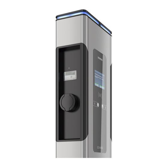
Description 3.2 Charging station structure Charging station structure ① Status light ② RFID reader ③ Viewing window for meter ④ Charging connection type 2 ⑤ Pushbutton ⑥ Maintenance door Figure 3-1 Charging station structure SICHARGE Operating Instructions MID Operating Instructions, 07/2020, A5E48573001-AB... -
Page 22: Charging Module Structure
Description 3.3 Charging module structure Charging module structure Options and accessories may vary. SICHARGE Operating Instructions MID Operating Instructions, 07/2020, A5E48573001-AB... -
Page 23: Flowchart
Description 3.4 Flowchart ① Multiple door lock ② Status light for each charging point ③ Control cabinet fan ④ Charging controller ⑤ Viewing window for meter ⑥ Electricity meter ⑦ Charging socket type 2 ⑧ Fuses for charging points ⑨ Residual current circuit breaker ⑩... -
Page 24: 3.5 Charging Controller
Description 3.5 Charging controller Charging controller ① Charge point 1, electric meter connection ② Charge point 1, charging module controller (CB, RCCB, contactor, charging socket, status indica- tor) ③ Charge point 2, electric meter connection ④ Charge point 2, charging module controller (CB, RCCB, contactor, charging socket, status indica- tor) ⑤... - Page 25 The SIM card is required for communication, e.g. with the backend. The SIM card is not included in the standard delivery of the charging station. If desired, an optional pre-configuration can be carried out at the manufacturer. Contact your Siemens branch for more information.
-
Page 26: Mounting/Assembly
Mounting/assembly Safety measures during assembly General information Charging of electric cars must guarantee high performance over long periods. The installation and pre-installation of the charging station must comply with the power requirements. To ensure that these requirements are fulfilled correctly, these installation instructions are intended for qualified and trained electricians. -
Page 27: Preparation Before Assembly
• Prepare and position the concrete foundation according to the "foundation and reinforcement plan" of the respective installation type. – Foundation and reinforcement plan for standard version (https://support.industry.siemens.com/cs/ww/de/view/109780588) – Foundation and reinforcement plan for option: HAK (https://support.industry.siemens.com/cs/ww/de/view/109780588) • Anchor the four segment anchor rods or the mounting plate in the concrete foundation according to the "Foundation and reinforcement plan"... - Page 28 Mounting/assembly 4.2 Preparation before assembly Required tools The required tools are not included in the scope of delivery. • Combination wrench set up to 19 width across flats • Key for housing (in the accessory kit) • Spirit level • Phillips head screwdriver set •...
-
Page 29: Assembly Procedure
Mounting/assembly 4.3 Assembly procedure Assembly procedure Specific safety measures DANGER Risk of electric shock when moist due to condensed water Before commissioning the charging station, an authorized and qualified electrician must check whether there is moisture in the charging station. Remove even small amounts of condensed water before commissioning. - Page 30 Mounting/assembly 4.3 Assembly procedure WARNING Risk of accident Risk of accident in limited space. Leave sufficient clearance to surrounding obstacles to avoid collisions and crushing when setting up the charging station. • Ensure that there is sufficient clearance to the surrounding obstacles when setting the load down.
- Page 31 Mounting/assembly 4.3 Assembly procedure Preparing the foundation Check that the foundation is horizontal using a spirit level. ① Cable entry, view from the bottom Figure 4-1 Foundation, base view Figure 4-2 Top view of the foundation SICHARGE Operating Instructions MID Operating Instructions, 07/2020, A5E48573001-AB...
- Page 32 Note HAK option With the HAK option, the foundation and cable routing are different than shown in this figure. The foundation and reinforcement plan can be found here (https://support.industry.siemens.com/cs/ww/de/view/109780588). ① Drill holes for M12 threaded rods Figure 4-3 Drill picture...
- Page 33 Mounting/assembly 4.3 Assembly procedure Opening the housing WARNING Crushing hazard The weight of the standard version is 75 kg. Depending on the options ordered, the weight differs from the standard version. Lifting the unit may result in hazards that could cause not only serious material damage but also serious injury.
- Page 34 Mounting/assembly 4.3 Assembly procedure The keys for the unit and the control cabinet are on the right. To open the housing, follow these steps: 1. Turn the unit key to the right. Hold the key in this position. 2. To unlock the door, turn the switch cabinet key to the right. Mounting the charging station onto the concrete foundation 1.
- Page 35 Mounting/assembly 4.3 Assembly procedure 10. Mount the sealing plate flush with the mounting plate. Figure 4-4 Cable entry SICHARGE Operating Instructions MID Operating Instructions, 07/2020, A5E48573001-AB...
- Page 36 Mounting/assembly 4.3 Assembly procedure 11. Fill the charging station with base filler up to the black line (e.g. Hager ZAY95075). Figure 4-5 Marking for base filler SICHARGE Operating Instructions MID Operating Instructions, 07/2020, A5E48573001-AB...
- Page 37 Mounting/assembly 4.3 Assembly procedure Sticker with the quick reference guide for charging The charging station is supplied with a sheet of stickers. The stickers describe the procedure for starting and ending the charging. After setting up the charging station, stick the stickers underneath the meter window of each charge point.
-
Page 38: Connection And Commissioning
Connection and commissioning Connecting the supply cable Select the cable cross-section according to load and voltage drop: Note Three-phase operation The charging station may only be operated with 3 phases + N + PE. The specifications can be obtained from the rating plate (Page 18). •... - Page 39 Connection and commissioning 5.1 Connecting the supply cable To connect the supply cable, proceed as follows: 1. Sheath the power supply cable above the strain relief. Make the protective conductor at least 50 mm longer than L and N. 2. Lay the cables in the housing in loops, as shown in the following figure. Figure 5-1 Infeed unit Note...
- Page 40 The electrical circuit diagram is located in the maintenance door in the document compartment of the SICHARGE charging station. The electrical circuit diagram can be downloaded here (https://support.industry.siemens.com/cs/ww/de/view/109780588). See also Options available for orders (Page 100) SICHARGE Operating Instructions MID...
-
Page 41: Optional Equipment
Connection and commissioning 5.2 Optional equipment Optional equipment Optional equipment ① Last Gasp ② Overvoltage and lightning protection ③ Double terminal Figure 5-2 Order options Last Gasp The Last Gasp function is an option that can be ordered additionally. This option includes an internal add-on module that does the following in the event of a power failure: •... - Page 42 Connection and commissioning 5.2 Optional equipment Overvoltage protection If you have ordered the overvoltage protection option, an additional internal add-on module is installed. This module is a 4-pin combination arrester with a remote signaling contact. It limits the follow-on current, displays errors, and outputs a trip notification via OCPP. For technical specifications, see section Options available for orders (Page 100).
-
Page 43: Sim Card
Connection and commissioning 5.3 SIM card SIM card The charging station uses the SIM card to establish a connection to the backend. The SIM card used must be able to operate in a closed APN. Otherwise, the communication to the charging station is not secure. - Page 44 Connection and commissioning 5.3 SIM card 3. Insert the SIM card correctly into the SIM card slot or remove the SIM card ① SIM card slot 4. Fit the card cover of the charging controller Note Removed SIM card The charging station can be operated without a SIM card only under certain conditions. 5.
-
Page 45: Switching On And Testing
Connection and commissioning 5.4 Switching on and testing Switching on and testing Procedure for switching on and checking the charging station. Perform the following steps to switch on the charging station. 1. Switch the power supply on. Switch on the backup fuses, the load breaker switch and the RCCB. 2. - Page 46 Connection and commissioning 5.5 Commissioning Change Password We recommend changing the password during commissioning. Comply with current rules of applicable IT standards for creating and managing secure passwords. NOTICE Manage password Manage the new password carefully. The password cannot be reset or retrieved on site. The password can be reset via the backend.
- Page 47 Connection and commissioning 5.5 Commissioning Dashboard The status of the connections is shown in tab "Dashboard". Figure 5-4 Dashboard SICHARGE Operating Instructions MID Operating Instructions, 07/2020, A5E48573001-AB...
- Page 48 Connection and commissioning 5.5 Commissioning Network/Interfaces Set the network connection in the "Network/Interfaces" tab. Select "Use DHCP" to reach the charging station with a name. Remove the check mark to enter the network settings. For remote maintenance and updates, you must set the check mark for "Enable VPN" and enter the port setting.
- Page 49 SIM card The SIM card must be operated in a closed APN. Otherwise, SICHARGE AC22 is vulnerable and a sustainable connection cannot be guaranteed. Should you have any questions, contact the relevant Siemens branch. Figure 5-6 Network Mobile SICHARGE Operating Instructions MID...
- Page 50 Connection and commissioning 5.5 Commissioning Network/Proxy Set the proxy connection in the "Network/Proxy" tab. Select "Use Proxy" to install the system behind a proxy server. Now, enter the proxy data in these fields. Enter proxy credentials in the "User" and "Password" fields. Figure 5-7 Network Proxy SICHARGE Operating Instructions MID...
- Page 51 You do not need to change anything in the "Chargebox ID (Template)" field. If the backend requests the Chargebox ID, enter this separately in the "Chargebox ID (Template)" field. Enter the authorization key provided by the backend in the "Authorization Key" field. Figure 5-8 OCPP Siemens SICHARGE Operating Instructions MID Operating Instructions, 07/2020, A5E48573001-AB...
- Page 52 Connection and commissioning 5.5 Commissioning Figure 5-9 OCPP custom SICHARGE Operating Instructions MID Operating Instructions, 07/2020, A5E48573001-AB...
- Page 53 Connection and commissioning 5.5 Commissioning Station/Date/Time Set the time zone and synchronization in the "Station/Date/Time" tab. If you check the "Timezone" box, the time zone of your browser is automatically applied. Clear the check box to select the time zone in the drop-down menu. In the area of "Synchronize date and time via", set the check mark for "NTP"...
- Page 54 Connection and commissioning 5.5 Commissioning Station/components Carry out a firmware update in the "Station/components" tab. NOTICE Overwriting firmware Ensure that the charging processes have been completed properly before overwriting the firmware. Figure 5-11 Station Components SICHARGE Operating Instructions MID Operating Instructions, 07/2020, A5E48573001-AB...
- Page 55 Connection and commissioning 5.5 Commissioning Station/Connectors The tab "Station/Connectors" has the following items: Points Status Meaning EVSE ✓ Electric Vehicle Supply Equipment ✓ Identification of the charging point Type ✓ Charging point type Hardware ID ✓ Hardware identification number Firmware ✓...
- Page 56 Connection and commissioning 5.5 Commissioning Figure 5-12 Station Connectors1 SICHARGE Operating Instructions MID Operating Instructions, 07/2020, A5E48573001-AB...
- Page 57 Connection and commissioning 5.5 Commissioning Figure 5-13 Station Connectors2 SICHARGE Operating Instructions MID Operating Instructions, 07/2020, A5E48573001-AB...
- Page 58 Connection and commissioning 5.5 Commissioning Station/Power WARNING Entering the maximum current for each outer conductor Only a qualified electrician can make an entry in this field. Enter the maximum available current for each phase in mA for the charging station. The value must not exceed the rated current of the back-up fuse.
- Page 59 Connection and commissioning 5.5 Commissioning GUI/Branding Set the HMI displays in the "GUI/Branding" tab. Figure 5-15 GUI Branding SICHARGE Operating Instructions MID Operating Instructions, 07/2020, A5E48573001-AB...
- Page 60 Connection and commissioning 5.5 Commissioning Language Select the language of the HMI display in the "Language" tab. Figure 5-16 GUI Language SICHARGE Operating Instructions MID Operating Instructions, 07/2020, A5E48573001-AB...
- Page 61 Connection and commissioning 5.5 Commissioning Advertisement Set up HMI advertising in the "Advertisement" tab. Select the provider if it does not correspond to the backend. Enter the URL, user and password for the advertisement. Set the update interval for the advertising file in "Data Synchronization". Set the time until advertising begins in "Display Timeout".
- Page 62 Connection and commissioning 5.5 Commissioning Authentication Set the authentication in the "User Managment/Authentication" tab. Selection Meaning ? any RFID If recognized, use any RFID. x no RFID Do not use RFID in any check. ✓ a white- Use the whitelist when checking the RFID. listed RFID Figure 5-18 User Management Authentication...
- Page 63 Connection and commissioning 5.5 Commissioning Users (RFID Cards) Tab "User Managment/Users (RFID Cards)" provides an overview of customers. In this tab, you can change the status of the customer. Click on the respective icon to change the status of a customer between active / inactive and valid / invalid.
- Page 64 Connection and commissioning 5.5 Commissioning Software The "Software" tab displays the currently installed software of the charging station. Figure 5-20 Software Concluding commissioning 1. Disconnect the LAN cable from the charging station. 2. Lock the housing door with the key. 3.
-
Page 65: Operation
Operation Status indicators Notes on operation The SICHARGE CC AC22 charging station is equipped with status indicators. Different colors and flashing signals indicate the current status of charging points 1 and 2. This signalizes to drivers if the charging station is available and what its status is. The display also directly shows the required information. - Page 66 Operation 6.1 Status indicators Status indicators The following table provides an overview of status indicators of charging points: Does not light up If the status indicator does not light up, this indicates an interruption to the power supply. If there is not a power failure, check the backup fuses.
-
Page 67: Main Menu
Operation 6.2 Main menu Main menu Symbols in the main menu When you switch on the charging station, you will see the following picture on the display. ① Charging station and connection status ② Display of instructions ③ Charging point indicator Figure 6-2 Main menu SICHARGE Operating Instructions MID... - Page 68 Operation 6.2 Main menu Table 6- 1 Symbols of the charging station and connection status Hardware fault Charging point status Charging station reserved Mobile network reception, network strength Mobile network reception, data connection (GSM, 2G, 3G, LTE) Connection to the OCPP backend RFID card reader SIM card (controller) Table 6- 2...
- Page 69 Operation 6.2 Main menu Charging status Circuit breaker status Available power Query to the meter The help menu contains a description of icons. You can access the help menu by pressing both buttons simultaneously or by pressing a button for a long time. Color scheme for the status bar Green OK / active...
-
Page 70: Charging
Operation 6.3 Charging Charging Safety instructions during the charging process DANGER Risk of electric shock and fire Touching live parts may cause electric shock or even death! Defective connectors or cables may cause fire. • Do not kink or squeeze the charging cable. Do not draw the charging cable over sharp edges or hot surfaces. - Page 71 Operation 6.3 Charging Different models The charging process is described for the socket with type 2 charging port. The procedure is largely identical for the following versions. • SCHUKO socket type E (other types available on request) • Fixed charging cables type 2 Possible deviations in the procedure: •...
- Page 72 Operation 6.3 Charging The status LED pulsating in blue indicates that current is flowing to the vehicle and the vehicle battery is charging. The status LED lights up permanently in blue in the following cases: • The vehicle is not drawing power. –...
- Page 73 Operation 6.3 Charging Procedure with operator app, hotline Proceed as follows to end the charging process with the operator app or hotline: 1. Charging point selection: Select your vehicle or the charging point by the operator. 2. Unlock the charging cable on the charging station. The status indicator changes from blue to yellow.
-
Page 74: Faults
Faults Fault elimination DANGER Risk of electric shock and fire Touching live parts may cause electric shock or even death! Damaged charging cables and connectors can cause a fire. • The system may only be opened and repaired by the manufacturer, its service department or similarly qualified persons. -
Page 75: Rfid Fault
Faults 7.2 Service technician faults 7.2.2 RFID fault RFID fault message If there is a fault on the RFID reader, the following message is shown on the display. Description Cause Solution RFID card not recognized RFID reader not (properly) connected. Check whether the RFID reader is correctly con- nected to the RFID board (VEN_ADA0). - Page 76 Faults 7.2 Service technician faults Status messages to the backend The various status messages are listed in the following table. Table 7- 1 OCPP NoError message Message frame text Message frame text Component Description Charging station ⇒ Backend ⇒ Charging Backend station NoError...
- Page 77 Faults 7.2 Service technician faults Overvoltage protection Message frame text Charging station ⇒ Backend: OtherError (OverVoltageProtectionFailure) Message frame text Backend ⇒ Charging station: Available Component: Charging station Status LED: No effect Description Cause Solution Overvoltage protection fault Loose terminal Check the overvoltage protection and the signaling contact.
- Page 78 Faults 7.2 Service technician faults Excess temperature fault Message frame text Charging station ⇒ Backend: HighTemperature Message frame text Backend ⇒ Charging station: Faulted Component: Charge point 1 or 2 Status LED: Flashes red 1x Description Cause Solution The temperature has exceeded the Fan is defective Replace the defective fan.
- Page 79 Faults 7.2 Service technician faults RCCB fault Message frame text Charging station ⇒ Backend: GroundFailure Message frame text Backend ⇒ Charging station: Faulted Component: Charge point 1 or 2 Status LED: Flashes red 4x Description Cause Solution Ground fault detected RCCB has tripped.
- Page 80 Faults 7.2 Service technician faults Undervoltage fault Message frame text Charging station ⇒ Backend: UnderVoltage Message frame text Backend ⇒ Charging station: Faulted Component: Charge point 1 or 2 Status LED: Flashes red 6x Description Cause Solution Undervoltage detected The voltage along the cable is below Check the power supply.
-
Page 81: Faqs
Faults 7.3 FAQs FAQs Frequently Asked Questions (FAQ) The following table shows an excerpt of possible messages. The symbols, their meanings and solutions are described in the three columns. Symbol Meaning Solution Vehicle not connected Connect the charging cable to the vehicle. Check the charging cable. - Page 82 Faults 7.3 FAQs Symbol Meaning Solution Vehicle connected Status message when you are logged in. (e.g. via smart phone, RFID card, etc.) Select the charging point. Follow the instructions on the display. Connection OK Cable lock error Disconnect the charging cable and recon- nect it.
- Page 83 Faults 7.3 FAQs Symbol Meaning Solution 75% or less of the max. power (22 kW) is available 50% or less of the max. power (22 kW) is available 25% or less of the max. power (22 kW) is available Charging point cover OK Charging point cover open.
- Page 84 Faults 7.3 FAQs Symbol Meaning Solution The PC has no connection to the Check the cabling. EVSE controller. The EVSE controller has incorrect Install the latest firmware. firmware. Charging station reserved Status message The charging process will start as soon as possible (requires RFID card assigned to the reservation).
-
Page 85: Maintenance And Service
Maintenance and service Cleaning and maintenance Safety measures Note Before cleaning or service work, disconnect the system from the power and ensure it cannot be switched back on. To do this, deactivate at least all fuses to which the charging station is connected. - Page 86 Maintenance and service 8.1 Cleaning and maintenance Cleaning guidelines • Do not use solvents or corrosive or abrasive detergents. • Use a mild, non-corrosive cleaning agent, e.g. dishwashing detergent, even if heavily soiled. • Wipe the charging station from the outside with a moist cloth and rub the station dry. •...
-
Page 87: Maintenance
Maintenance and service 8.2 Maintenance Maintenance Note High currents flow over a long period of time when charging the electric vehicle. The electrical installation of the charging station must be checked regularly to prevent overheating of cables and resulting damage. Note Only qualified personnel trained for these activities may perform this work. - Page 88 Maintenance and service 8.2 Maintenance Note You must immediately report any damage to seals, in particular damage to electrical equipment or wiring, or missing seals or covers to the operator. Shut the unit down. Inspecting fixed charging cables Inspect fixed charging cables, charging plugs, and charging plug holders regularly for the following: •...
- Page 89 Maintenance and service 8.2 Maintenance Maintenance of fans and filter mats In the course of checking the safety equipment, check the function of the fans twice yearly and replace the filter mats on a preventive basis. Pollution may be lighter or heavier depending on the place of installation. Adapt the inspection and replacement interval of the filter mats to the place of installation.
-
Page 90: Diagnostic Tests
Non-compliance will void the manufacturer's warranty and invalidate the approvals. Software updates Software updates Siemens makes software updates available as part of ongoing feature enhancements and improvements. Check the software version of your system (Page 63) regularly. Keep the software version of your system up-to-date with software updates. -
Page 91: Adhesive Surfaces
Adhesive surfaces Adhesive surfaces Marking of adhesive surfaces The hatched areas of the following drawings must not be covered with glue, paint or covered. The supplied quick reference guide is an exception. The quick reference guide is affixed underneath the meter inspection window. Ventilation slots and the maintenance door must not be restricted or obstructed. - Page 92 Adhesive surfaces 9.1 Adhesive surfaces Note Option: Full or partial foiling As an option, you can order foiling including adhesive from the factory. SICHARGE Operating Instructions MID Operating Instructions, 07/2020, A5E48573001-AB...
-
Page 93: Service & Support
• Forums For answers and solutions in all matters of automation technology. • mySupport Your personal working area in Siemens Industry Online Support for notifications, support queries, and configurable documents. This information is provided by Siemens Industry Online Support (https://support.industry.siemens.com/cs/ww/)on the internet. -
Page 94: Disposal
Disposal 11.1 Recycling and disposal Disposing of packaging The packaging of the SICHARGE AC22 contains no hazardous substances. Send the packaging for recycling in accordance with the applicable regulations in your country. Disposing of the battery Do not dispose of batteries with household waste. Follow local, national, and international regulations to dispose of the battery. -
Page 95: Technical Specifications
Technical specifications 12.1 Technical specifications Performance features and options SICHARGE Designation CC AC22 ● Standard, O available as an option Charge points type 2, 32 A acc. to IEC 62196-1,2 and 61851-1 Connector lock type 2 ● Flap lock type 2 ●... - Page 96 Technical specifications 12.1 Technical specifications Technical specifications Designation SICHARGE CC AC22 Display 7" LED Connection voltage AC 400 V ± 10% 3-phase N+PE Connection frequency 50/60 Hz Maximum connected power 63 A / phase Load management acc. to maximum infeed, chronological 6 ...
- Page 97 Technical specifications 12.1 Technical specifications Storage and transport Follow the following framework conditions when storing and transporting the charging station: • The permissible storage temperature of the charging station is -25 to +50 °C. • The permissible air humidity is 5 to 95%, non-condensing. •...
-
Page 98: Appendix
Appendix Spare parts Spare parts The spare parts listed are available for the charging station. Spare part Article number Weight in kg Display unit SICHARGE FZI:40094.013 Charging socket type 2 SV+KDV FZI:40094.014 Earthed charging socket 16A 230V, type E FZI:40094.015 Inspection window SICHARGE FZI:40094.016 Key EMKA for half cylinder 1089-U2, spare key 12B-140... -
Page 99: Installation And Maintenance Schedule
Appendix A.2 Installation and maintenance schedule Installation and maintenance schedule SICHARGE AC22 checklist The following table shows the tasks and their expected duration for the following applications: • Installation/assembly • Commissioning • Maintenance Table A- 1 Installation and maintenance schedule Action Installa- Commis-... - Page 100 Appendix A.2 Installation and maintenance schedule Action Installa- Commis- Mainte- Duration tion/asse sioning nance in min. mbly Check axial fan for: • Function • Running noise • Cleaning Once the charging station has been switched on, the fans run for 15 minutes (test mode) Change air filters on the bottom of the charging station Check the RCCB (semi-annual DGUV V3) including protocol...
-
Page 101: Options Available For Orders
Appendix A.3 Options available for orders Options available for orders Option overview These extensions can be optionally ordered for the SICHARGE CC AC22 . Options and accessories Description Permanently installed type 2 Instead of charge point sockets, spiral charging cables type 2, in- charging cable at both ends cluding holder, are installed. -
Page 102: Option: Hak
Appendix A.4 Option: HAK Option: HAK HAK building junction box The HAK building junction box shown in the illustration is available in the following versions. Figure A-1 HAK housing, without equipment The HAK housing is available in various models for the installation of a building junction box and a meter cabinet. - Page 103 Appendix A.4 Option: HAK HAK housing, without equipment The following is set up when a HAK housing without equipment is ordered. • Mounting points for meter cabinet and building junction box • Connection cable between the HAK housing and the charging station Connecting the supply cable DANGER Risk of electric shock...
-
Page 104: Option: Schuko Socket
Appendix A.5 Option: SCHUKO socket Option: SCHUKO socket SCHUKO socket type D, E, or F The SCHUKO socket shown in the illustration is available in the following versions. • Type D (on request) • Type E • Type F (on request) Figure A-2 SCHUKO socket SICHARGE Operating Instructions MID... - Page 105 Appendix A.5 Option: SCHUKO socket Operating the charge point The charge point automatically detects the interface to which a consumer was connected. Only this interface is supplied with energy when the charging starts. Note You can draw energy via either the SCHUKO socket or the type 2 connection. Only one connection can be operated at one charge point at any given time.
-
Page 106: Option: Fixed Charging Cable
Appendix A.6 Option: Fixed charging cable Option: Fixed charging cable Fixed charging cables type 2 Fixed charging cables type 2 shown in this illustration are available as an option. Table A- 2 Fixed charging cables type 2 Charging cable type 2 Type 2 charging cable and SCHUKO socket The fixed charging cables type 2 are stowed in the brackets on the side of the charging... -
Page 107: Overview Of Dimensions Of The Sicharge Cc Ac22 Charging Station
Appendix A.7 Overview of dimensions of the SICHARGE CC AC22 charging station Overview of dimensions of the SICHARGE CC AC22 charging station Dimension drawing of charging station Figure A-3 Dimension drawing of charging station SICHARGE Operating Instructions MID Operating Instructions, 07/2020, A5E48573001-AB... - Page 108 Dimension drawing of charging station with HAK Figure A-4 Dimension drawing of charging station with HAK Foundation and reinforcement plan The foundation and reinforcement plan for the respective version can be found here (https://support.industry.siemens.com/cs/ww/de/view/109780588). SICHARGE Operating Instructions MID Operating Instructions, 07/2020, A5E48573001-AB...
-
Page 109: Quality Documentation
The EC Declarations of Conformity are kept available for the responsible authorities at: Siemens AG Smart Infrastructure Distribution Systems Mozartstr. 31c 91052 Erlangen, Germany These files are also available for download on the Siemens Industry Online Support (https://support.industry.siemens.com/cs/ww) pages, under "Declaration of Conformity". SICHARGE Operating Instructions MID Operating Instructions, 07/2020, A5E48573001-AB... -
Page 110: List Of Abbreviations
List of abbreviations Abbreviations Access Point Name Gateway access point EVSE Electric Vehicle Supply Equipment RCCB Residual Current Circuit Breaker Graphical User Interface Graphical user interface Building junction box LVDS Low Voltage Differential Signaling Measurement Instruments Directive OCPP Open Charge Point Protocol The National Metrology Institute of Germany SCHUKO Socket outlet with grounding contact...
Need help?
Do you have a question about the SICHARGE CC AC22-MID and is the answer not in the manual?
Questions and answers