
Related Manuals for Siemens SICHARGE SICHARGE CC AC22 - MID


Summary of Contents for Siemens SICHARGE SICHARGE CC AC22 - MID
- Page 1 Edition 02/2023 OPERATING INSTRUCTIONS SICHARGE SICHARGE CC AC22 - MID (8EM1000-XBXXX-XXXX) siemens.com/sicharge...
- Page 2 Introduction Safety information SICHARGE Description SICHARGE CC AC22 - MID SICHARGE Operating Instructions Mounting/assembly Connection and commissioning Operating Instructions Operation Faults Maintenance and service Adhesive surfaces Service & Support Disposal Technical specifications Appendix List of abbreviations 02/2023 A5E48573001-AF...
- Page 3 Note the following: WARNING Siemens products may only be used for the applications described in the catalog and in the relevant technical documentation. If products and components from other manufacturers are used, these must be recommended or approved by Siemens. Proper transport, storage, installation, assembly, commissioning, operation and maintenance are required to ensure that the products operate safely and without any problems.
-
Page 4: Table Of Contents
Table of contents Introduction............................Purpose of this documentation..................Conventions........................Open-source software....................... Safety information..........................General safety information....................Safe installation and assembly..................Safety during electrical installation..................13 Safety during operation....................14 Safe cleaning and maintenance..................15 Security information......................16 Safety-relevant symbols....................17 Identification of the device MID.................. - Page 5 Cleaning and maintenance....................81 Maintenance........................Diagnostic tests........................ 85 Software updates......................85 Adhesive surfaces..........................86 Adhesive surfaces......................86 Service & Support..........................88 10.1 Siemens Industry Support....................88 Disposal.............................. 11.1 Recycling and disposal...................... 89 Technical specifications........................90 12.1 Technical specifications....................Appendix............................Overview of article numbers..................... 94 Spare parts........................
- Page 6 Table of contents A.10 Quality documentation..................... 109 List of abbreviations........................... 111 Abbreviations........................111 SICHARGE Operating Instructions MID Operating Instructions, 02/2023, A5E48573001-AF...
-
Page 7: Introduction
Introduction Purpose of this documentation These operating instructions contain the information required for installing, commissioning, and operating the SICHARGE CC AC22 charging station. The operating instructions contain information on proper use of the charging station. WARNING Failure to comply with the information in these operating instructions may result in the following: •... -
Page 8: Open-Source Software
Siemens accepts no liability for the use of the open-source software over and above the intended program sequence, or for any faults caused by modifications to the software. -
Page 9: Safety Information
Safety information General safety information This section contains important, generally valid information on: • Avoiding accidents or damage to property • Application planning • Mounting and installation • Operation • Maintenance and cleaning of the charging station Read this section carefully and follow the safety regulations. This will minimize safety risks. Make your staff and customers aware of this section. - Page 10 Safety information 2.1 General safety information Areas of application of the device • Charging electrically operated vehicles in public and semi-public areas • Charging stations for depots, car parks, public parking areas, and retail • Stations for car-to-go projects Intended use The device serves to charge batteries in fully electric and plug-in hybrid electric vehicles.
-
Page 11: Safe Installation And Assembly
Safety information 2.2 Safe installation and assembly Safety equipment To rule out hazardous conditions, it is strictly prohibited to change, remove, bypass, or override safety devices. Failure to follow these instructions may result in hazardous situations that could cause death or serious injury. - Page 12 Safety information 2.2 Safe installation and assembly Safety at the work site When working on roads, construction sites and in public areas, ensure safety in line with local requirements and regulations. To perform the work properly, you need to observe: •...
-
Page 13: Safety During Electrical Installation
Safety information 2.3 Safety during electrical installation Crushing hazard The weight of the standard version is 75 kg. Depending on the options ordered, the weight differs from the standard version. Lift the charging station with at least two persons and suitable lifting equipment. Lifting the station may result in hazards that could cause not only serious material damage but also serious injury. -
Page 14: Safety During Operation
Safety information 2.4 Safety during operation Do not perform any installation, maintenance, or configuration work during a thunderstorm. Do not connect the vehicle to or disconnect it from the charging station during a storm. Damage to sockets and charging cable Inspect sockets and the charging cable for damage on a regular basis. -
Page 15: Safe Cleaning And Maintenance
Safety information 2.5 Safe cleaning and maintenance • Provide for adequate space in the working area. The working area should be at least 8 meters in diameter. • Comply with the valid building regulations for parking spaces for electric cars including charging stations. -
Page 16: Security Information
In order to protect plants, systems, machines, and networks against cyber threats, it is necessary to implement – and continuously maintain – a holistic, state-of-the-art industrial security concept. Siemens’ products and solutions constitute one element of such a concept. Operators of the charging station are responsible for preventing unauthorized access to their plants, systems, machines, and networks. -
Page 17: Safety-Relevant Symbols
Safety information 2.8 Identification of the device MID Safety-relevant symbols Icons for SICHARGE CC AC22 The following table explains icons than may be located on your product, on its packaging, or in the accompanying documentation. Symbol Meaning General warning sign Caution/Notice You must read the product documentation. - Page 18 Information on the nameplate will help service and support with troubleshooting and procuring matching spare parts. For this reason, do not remove the rating plate. Make sure that the information is legible. Siemens AG, Mozartstr. 31c, DE-91058 Erlangen VOLTAGE Connection voltage CURRENT Max.
-
Page 19: Description
Description Application This charging station is a first-class, cutting edge product. You can charge electrically powered vehicles safely and reliably with the SICHARGE CC AC22 charging station. Charging stations can be used for stand-alone operation. They can also be integrated into flexible, modular, and retrofittable infrastructure. -
Page 20: Charging Station Structure
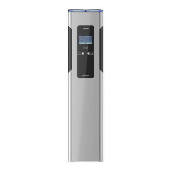
Description 3.2 Charging station structure Charging station structure ① Status light ⑤ Charging connection type 2 ② ⑥ Pushbutton ③ Viewing window for meter ⑦ Maintenance door ④ RFID reader ⑧ Option: Fixed charging cable Figure 3-1 Charging station structure SICHARGE Operating Instructions MID Operating Instructions, 02/2023, A5E48573001-AF... -
Page 21: Charging Module Structure
Description 3.3 Charging module structure Charging module structure Options and accessories may vary. ① Multiple door lock ② Status light for each charging point ③ Control cabinet fan ④ Charging controller ⑤ Viewing window for meter SICHARGE Operating Instructions MID Operating Instructions, 02/2023, A5E48573001-AF... -
Page 22: Flowchart
Description 3.4 Flowchart ⑥ Electricity meter ⑦ Charging socket type 2 ⑧ Fuses for charging points ⑨ Residual current circuit breaker ⑩ Contactor for charging point ⑪ Power supply unit ⑫ Charging controller fuse ⑬ PE terminal ⑭ Load breaker switch ⑮... -
Page 23: Charging Controller
Description 3.5 Charging controller Charging controller SICHARGE Operating Instructions MID Operating Instructions, 02/2023, A5E48573001-AF... - Page 24 Description 3.5 Charging controller ① Charge point 1, electric meter connection ② Charge point 1, charging module controller (CB, RCCB, contactor, charging socket, status indic ator) ③ 4G module or Ethernet module ④ Charge point 2, electric meter connection ⑤ Charge point 2, charging module controller (CB, RCCB, contactor, charging socket, status indic...
- Page 25 The SIM card is required for communication, e.g. with the backend. The SIM card is not included in the standard delivery of the charging station. If desired, an optional pre-configuration can be carried out at the manufacturer. Contact your Siemens branch for more information.
-
Page 26: Mounting/Assembly
Mounting/assembly Safety measures during assembly General information Charging of electric cars must guarantee high performance over long periods. The installation and pre-installation of the charging station must comply with the power requirements. To ensure that these requirements are fulfilled correctly, these installation instructions are intended for qualified and trained electricians. -
Page 27: Preparation Before Assembly
• Prepare and position the concrete foundation according to the "foundation and reinforcement plan" of the respective installation type. – Foundation and reinforcement plan for standard version (https://support.industry.siemens.com/cs/ww/de/view/109780588) – Foundation and reinforcement plan for option: HAK (https://support.industry.siemens.com/cs/ww/de/view/109780588) • Anchor the four segment anchor rods or the mounting plate in the concrete foundation according to the "Foundation and reinforcement plan"... -
Page 28: Assembly Procedure
Mounting/assembly 4.3 Assembly procedure Required material The required material is not included in the delivery. • Concrete foundation • Reinforcement • Mounting plate, anchor system or threaded rods • Empty pipe or corrugated pipe • Cable tie set • Strain relief that matches the cable (i.e. OBO clamping bracket / BBS clamp) •... - Page 29 Mounting/assembly 4.3 Assembly procedure WARNING Risk of accident Using a crane or other mechanical lifting gear may result in hazardous situations that could cause death or severe injury. • Do not operate cranes or other mechanical lifting equipment when not instructed to do •...
- Page 30 Mounting/assembly 4.3 Assembly procedure You will also need consumables for the selected installation variant. DANGER Risk of electric shock due to exposed electrical connections and components Before starting the installation work, check that the supply cable has been disconnected from the mains and secured against restart. If damage or tampering is visible (e.g.
- Page 31 HAK option With the HAK option, the foundation and cable routing are different than shown in this figure. You can find the foundation and reinforcement plan here (https://support.industry.siemens.com/cs/ww/de/view/109780588). NOTE Ethernet interface version For the version with Ethernet interface, you require an additional empty tube or corrugated tube for the network cable.
- Page 32 Mounting/assembly 4.3 Assembly procedure ① Drill holes for M12 threaded rods Figure 4-3 Drill picture Opening the housing WARNING Crushing hazard The weight of the standard version is 75 kg. Depending on the options ordered, the weight differs from the standard version. Lifting the unit may result in hazards that could cause not only serious material damage but also serious injury.
- Page 33 Mounting/assembly 4.3 Assembly procedure The keys for the unit and the control cabinet are on the right. To open the housing, follow these steps: 1. Turn the unit key to the right. Hold the key in this position. 2. To unlock the door, turn the switch cabinet key to the right. Mounting the charging station onto the concrete foundation 1.
- Page 34 Mounting/assembly 4.3 Assembly procedure 9. Route the cable(s) through the sealing plate. NOTE Ethernet interface version When using a prefabricated network cable, sealing is not guaranteed by the sealing plate. Do not install the RJ45 plug on the network cable until step 9 has been completed. You can find more information in section Optional equipment (Page 39).
- Page 35 Mounting/assembly 4.3 Assembly procedure 11. Fill the charging station with base filler up to the black line (e.g. Hager ZAY95075). m en t Fil l in ba se he re fill er up to m it Bis hie rh er So ck elf üll er for furth er See man ual info rma on...
- Page 36 Mounting/assembly 4.3 Assembly procedure Figure 4-6 Position of the sticker SICHARGE Operating Instructions MID Operating Instructions, 02/2023, A5E48573001-AF...
-
Page 37: Connection And Commissioning
Connection and commissioning Connecting the supply cable Select the cable cross-section according to load and voltage drop: NOTE Three-phase operation The charging station may only be operated with 3 phases + N + PE. The specifications can be obtained from the rating plate (Page 17). •... - Page 38 Electrical circuit diagram in the document compartment and for download The electrical circuit diagram is located in the maintenance door in the document compartment of the SICHARGE charging station. The electrical circuit diagram can be downloaded here (https://support.industry.siemens.com/cs/ww/de/view/109780588). SICHARGE Operating Instructions MID Operating Instructions, 02/2023, A5E48573001-AF...
-
Page 39: Optional Equipment
Connection and commissioning 5.2 Optional equipment See also Options available for orders (Page 97) Optional equipment Optional equipment ① Last Gasp ② Ethernet interface ③ Overvoltage protection or lightning protection ④ Double terminal Figure 5-2 Order options Last Gasp The Last Gasp function is an option that can be ordered additionally. SICHARGE Operating Instructions MID Operating Instructions, 02/2023, A5E48573001-AF... - Page 40 A conversion kit is available for converting systems with a 4G module. To do this, follow the instructions in the Repair instructions (https://support.industry.siemens.com/cs/ww/en/view/109793281). Section Spare parts (Page 94) includes the article number of the conversion kit. You can find the overview of the various article numbers in the section Overview of article numbers (Page 93).
-
Page 41: Sim Card
Connection and commissioning 5.3 SIM card For technical specifications, see section Options available for orders (Page 97). Lightning protection If you have ordered the lightning protection option, an additional internal module is installed. This module is a 4-pin combination arrester with a remote signaling contact. The combination arrester limits the follow-on current and dissipates the lightning energy via dedicated grounding. - Page 42 Connection and commissioning 5.3 SIM card Insert/remove SIM card Follow the instructions below to insert or remove the SIM card: 1. Remove the two screws from the card cover of the charging controller ① Card cover 2. Remove the card cover from the charging controller 3.
-
Page 43: Switching On And Testing
Connection and commissioning 5.5 Commissioning and parameter assignment Switching on and testing Procedure for switching on and checking the charging station. Perform the following steps to switch on the charging station. 1. Switch the power supply on. Switch on the backup fuses, the load breaker switch and the RCCB. 2. - Page 44 Connection and commissioning 5.5 Commissioning and parameter assignment User Password http://192.168.32.1 admin <Serial number of the system> The serial number of the system can be found on the rating plate (Page 17). Change Password We recommend changing the password during commissioning. Comply with current rules of applicable IT standards for creating and managing secure passwords.
- Page 45 Connection and commissioning 5.5 Commissioning and parameter assignment Dashboard The status of the connections is shown in tab "Dashboard". Figure 5-4 Dashboard Network/Interfaces Set the network connection in the "Network/Interfaces" tab. Select "Use DHCP" to reach the charging station with a name. Remove the check mark to enter the network settings.
- Page 46 Connection and commissioning 5.5 Commissioning and parameter assignment For remote maintenance and updates, you must set the check mark for "Enable VPN" and enter the port setting. Figure 5-5 Network interface (DHCP active) SICHARGE Operating Instructions MID Operating Instructions, 02/2023, A5E48573001-AF...
- Page 47 The SIM card must be operated in a closed APN. Otherwise, SICHARGE AC22 is vulnerable and a sustainable connection cannot be guaranteed. Should you have any questions, contact the relevant Siemens branch. SICHARGE Operating Instructions MID Operating Instructions, 02/2023, A5E48573001-AF...
- Page 48 Connection and commissioning 5.5 Commissioning and parameter assignment Figure 5-7 Network Mobile Network/Proxy Set the proxy connection in the "Network/Proxy" tab. SICHARGE Operating Instructions MID Operating Instructions, 02/2023, A5E48573001-AF...
- Page 49 Connection and commissioning 5.5 Commissioning and parameter assignment Select "Use Proxy" to install the system behind a proxy server. Now, enter the proxy data in these fields. Enter proxy credentials in the "User" and "Password" fields. Figure 5-8 Network Proxy OCPP Set the operator in the "OCPP"...
- Page 50 Connection and commissioning 5.5 Commissioning and parameter assignment Enter the authorization key provided by the backend in the "Authorization Key" field. Figure 5-9 OCPP custom Station/Date/Time Set the time zone and synchronization in the "Station/Date/Time" tab. If you check the "Timezone" box, the time zone of your browser is automatically applied. Clear the check box to select the time zone in the drop-down menu.
- Page 51 Connection and commissioning 5.5 Commissioning and parameter assignment The check mark at "Browser (only once)" means that the browser time is only set once during commissioning, and will not be adjusted/updated. Figure 5-10 Station Date and Time Station/components If you encounter problems during a firmware update, you can also start the firmware update manually in the "Station/components"...
- Page 52 Connection and commissioning 5.5 Commissioning and parameter assignment See also Software updates (Page 85) Figure 5-11 Station Components Station/Connectors The tab "Station/Connectors" has the following items: Points Status Meaning EVSE ✓ Electric Vehicle Supply Equipment ✓ Identification of the charging point Type ✓...
- Page 53 Connection and commissioning 5.5 Commissioning and parameter assignment Points Status Meaning Serial ✓ Meter serial number Valid ✓ Meter valid/confirmed Value (Wh) ✓ Meter status Max. Current ✓ Max. output current in mA Max. Current ✓ Max. cable current in mA Cable Max.
- Page 54 Connection and commissioning 5.5 Commissioning and parameter assignment Figure 5-13 Station Connectors2 Station/Power WARNING Entering the maximum current for each line conductor Only an electrician may enter values into this field. Enter the maximum available current for each phase in mA for the charging station. The value must not exceed the rated current of the back-up fuse.
- Page 55 10% for each external conductor (to 56.7 A/39.1 kW). GUI/Branding Set the HMI displays in the "GUI/Branding" tab. Do not change the factory-set branding ("Siemens"). The information on the operator (name and URL) is only used for transfer to the backend, if necessary. SICHARGE Operating Instructions MID...
- Page 56 Connection and commissioning 5.5 Commissioning and parameter assignment Under Operator Contact/ Support Address, you can enter the phone number of the Support hotline that users of the charging station can call in the event of a fault (see also Fault elimination (Page 71)).
- Page 57 Connection and commissioning 5.5 Commissioning and parameter assignment Language Select the primary and secondary language of the HMI display in the "Language" tab (see also Display/GUI (Page 64)) Figure 5-16 GUI Language Advertisement Set up HMI advertising in the "Advertisement" tab. Select the provider if it does not correspond to the backend.
- Page 58 Connection and commissioning 5.5 Commissioning and parameter assignment Set the time until advertising begins in "Display Timeout". Figure 5-17 GUI Advertisement Authentication Set the authentication options in the "User Management/Authentication" tab. SICHARGE Operating Instructions MID Operating Instructions, 02/2023, A5E48573001-AF...
- Page 59 Connection and commissioning 5.5 Commissioning and parameter assignment Note that the charging station automatically recognizes this information when there is a connection to the backend; it will give priority to the authentication method set in the backend. It is also possible to push a release list via OCPP and make it available locally. Selection Meaning ? any RFID...
- Page 60 Connection and commissioning 5.5 Commissioning and parameter assignment Click on the respective icon to change the status between active/inactive and valid/invalid. NOTE Important Always confirm changes with a click on „Save“ so that the changes are transferred to the station. More details on the creation and import of local release lists are available in the section Whitelist (Page 103).
- Page 61 Connection and commissioning 5.5 Commissioning and parameter assignment When "Remote" is enabled, the plant operator can set up access via an SSH tunnel. Figure 5-20 User Management Security Software The "Software" tab displays the currently installed software of the charging station. Figure 5-21 Software SICHARGE Operating Instructions MID Operating Instructions, 02/2023, A5E48573001-AF...
- Page 62 Connection and commissioning 5.5 Commissioning and parameter assignment Concluding commissioning 1. Disconnect the Ethernet cable from the charging station. 2. Lock the housing door with the key. 3. Remove the packing material and protective films. 4. Clean the unit if required. 5.
-
Page 63: Operation
Operation Status indicators Notes on operation The SICHARGE CC AC22 charging station is equipped with status indicators. Different colors and flashing signals indicate the current status of charging points 1 and 2. This signalizes to drivers if the charging station is available and what its status is. The display also directly shows the required information. - Page 64 Operation 6.1 Status indicators Pulsating blue light Charging process active: The connected vehicle is receiving power. Lights up blue Charging inactive: The connected vehicle is not drawing any power. Flashing blue Meter data for the charging process are being signed. Flashes red 1x •...
-
Page 65: Display/Gui
Operation 6.2 Display/GUI Display/GUI Start screen After power on or after a few seconds without operation command, the station will show the start screen. ① Charging point 1 ④ Drawn energy charging point 1 ② Status display charging point 1 ⑤... - Page 66 Operation 6.2 Display/GUI Operator guidance The user of the charging station is guided through the operating steps using graphics. Some displays also show text references. The primary language and the secondary language are configured in the WebUI of the station. (See also Commissioning and parameter assignment (Page 43)) ①...
-
Page 67: Charging
Operation 6.3 Charging Status display Meaning Charging point inactive Charging Safety instructions during the charging process DANGER Risk of electric shock and fire Touching live parts may cause electric shock or even death! Defective connectors or cables may cause fire. •... - Page 68 Operation 6.3 Charging Different versions The charging process is described for the socket with type 2 charging port. The procedure is largely identical for the following versions. • SCHUKO socket type E/F • Fixed charging cables type 2 Possible deviations in the procedure: •...
- Page 69 Operation 6.3 Charging 4. Depending on the configuration (configuration via web interface or backend) of your device, the software will now check your authorization to charge a vehicle. 5. The charging station now unlocks the cover lock. 6. Plug the plug connector of the charging cable into the power outlet of the charging station.
- Page 70 Operation 6.3 Charging Procedure with RFID card Proceed as follows to end the charging process with the RFID card: 1. Charging point selection: Press the pushbutton below the display and follow the instructions. 2. Place the RFID card onto the icon for the card reader. Once the RFID card has been identified, the validity is checked.
-
Page 71: Faults
Faults Fault elimination DANGER Risk of electric shock and fire Touching live parts may cause electric shock or even death! Damaged charging cables and connectors can cause a fire. • The system may only be opened and repaired by the manufacturer, its service department or similarly qualified persons. - Page 72 Faults 7.1 Fault elimination Procedure in the event of a fault If the charging station experiences a fault, proceed as follows: 1. Check the display. The following options are available for diagnostics: – Screen maintenance status: Open the screen by pressing a button for five seconds (long press).
- Page 73 Faults 7.1 Fault elimination – Screen out of order: The displayed error code (for example, #40-02-00) can only be used for diagnostics and fault clearance (e.g. with the help of the Service hotline). Figure 7-2 Screen out of order – Flash codes of the LED status display (see Status indicators (Page 63)) –...
-
Page 74: Service Technician Faults
Faults 7.2 Service technician faults Cause Remedied by Solution Charging process – electric vehicle Operator Check if the battery is full. requires no power Check whether the vehicle cannot be charged because of the temperature (too hot or too cold). Check the cable and vehicle for faults. -
Page 75: Rfid Fault
Faults 7.2 Service technician faults 7.2.2 RFID fault RFID fault message In case of a fault at the RFID reader, the fault is displayed in the "Maintenance" screen. Description Possible causes Solution RFID card not recognized RFID reader not (properly) connected. Check whether the RFID reader is correctly con... - Page 76 Faults 7.2 Service technician faults Message frame text Message frame text Component Description Charging station ⇒ Backend ⇒ Charging Backend station NoError Unavailable Charging point 1 or 2 The EVSE sibling connector is occupied. NoError Reserved Charging point 1 or 2 Charging point reserved NoError SuspendedEVSE...
- Page 77 Faults 7.2 Service technician faults Status LED: No effect Description Cause Solution Overvoltage protection fault Loose terminal Check the overvoltage protection and the signaling contact. Overvoltage protection has tripped Change the overvoltage protection. Fault: EVSE connection error Message frame text Charging station ⇒ Backend: OtherError (EVSECommunicationError) Message frame text Backend ⇒...
- Page 78 Faults 7.2 Service technician faults Message frame text Backend ⇒ Charging station: Faulted Component: Charging point 1 or 2 Status LED: Flashes red 2x Description Cause Solution Main contactor fault The main contactor gets stuck. Replace the main contactor. Auxiliary contact faulty Check the auxiliary contact.
- Page 79 Faults 7.2 Service technician faults Connector lock fault Message frame text Charging station ⇒ Backend: ConnectorLockFailure Message frame text Backend ⇒ Charging station: Faulted Component: Charging point 1 or 2 Status LED: Flashes red 5x Description Cause Solution Connector lock error The locking mechanism is blocked by the Remove the plug from the socket.
- Page 80 Faults 7.2 Service technician faults Status LED: Flashes red 7x Description Cause Solution Mode 3 unknown status Communication problem with the 1. Disconnect the vehicle from the char vehicle. ging station. 2. Plug the vehicle back into the char ging station. •...
-
Page 81: Maintenance And Service
Maintenance and service Cleaning and maintenance Safety measures NOTE Before cleaning or service work, disconnect the system from the power and ensure it cannot be switched back on. Deactivate all fuses to which the charging station is connected. DANGER Risk of electrocution Touching live parts may cause electric shock or death. -
Page 82: Maintenance
Maintenance and service 8.2 Maintenance To ensure optimum quality and functionality, clean all charging stations according to agreed intervals. The display, in particular, requires regular maintenance. NOTE Use environmentally friendly cleaning agents approved for cleaning aluminum, glass, and ABS plastics. NOTE Only qualified personnel may clean the charging station from the inside. - Page 83 Maintenance and service 8.2 Maintenance Check the function of the residual current circuit breaker (RCCB) by pressing the test button "T". This test does not replace the measurement for resistance earthing (RE) or proper condition testing for the protective earth conductor. NOTE Note that you must perform the above test for each RCCB/MCB of the charging station.
- Page 84 Maintenance and service 8.2 Maintenance The figure below shows the positions of the fans and filter mats. Figure 8-1 Fans and filter mats NOTICE Electrical hazards The charging station uses 400 V AC supply voltage. Touching live parts may cause electric shock and could be fatal. Work on the electrical installation may only be carried out by trained electricians and at zero current.
-
Page 85: Diagnostic Tests
Non-compliance will void the manufacturer's warranty and invalidate the approvals. Software updates Software updates Siemens makes software updates available as part of ongoing feature enhancements and improvements. Check the software version of your system (Page 61) regularly. Keep the software version of your system up-to-date with software updates. -
Page 86: Adhesive Surfaces
Adhesive surfaces Adhesive surfaces Marking of adhesive surfaces The hatched areas of the following drawings must not be covered with glue, paint or covered. The supplied quick reference guide is an exception. The quick reference guide is affixed underneath the meter inspection window. Ventilation slots and the maintenance door must not be restricted or obstructed. - Page 87 Adhesive surfaces 9.1 Adhesive surfaces NOTE Option: Full or partial foiling As an option, you can order foiling including adhesive from the factory. SICHARGE Operating Instructions MID Operating Instructions, 02/2023, A5E48573001-AF...
-
Page 88: Service & Support
FAQs, certificates, downloads, and manuals at the following link (https://support.industry.siemens.com/cs/de/en/ps/28775). • mySupportYour personal working area in Siemens Industry Online Support for notifications, support queries, and configurable documents. This information is provided by Siemens Industry Online Support (https://support.industry.siemens.com/cs/ww/)on the internet. -
Page 89: Disposal
Disposal 11.1 Recycling and disposal Disposing of packaging The packaging of the SICHARGE AC22 contains no hazardous substances. Send the packaging for recycling in accordance with the applicable regulations in your country. Disposing of the battery Do not dispose of batteries with household waste. Follow local, national, and international regulations to dispose of the battery. -
Page 90: Technical Specifications
Technical specifications 12.1 Technical specifications Performance features and options Designation SICHARGE CC AC22 ● Standard, O available as an option Charging points type 2, 32 A acc. to IEC 62196-1,2 and 61851-1 Connector lock type 2 ● Flap lock type 2 ●... - Page 91 Technical specifications 12.1 Technical specifications Designation SICHARGE CC AC22 Double terminal (option A00) Last Gasp function Backend pre-configuration (integration test required) A list of order options can be found in section Options available for orders (Page 97) in the appendix. Technical specifications Designation SICHARGE CC AC22...
- Page 92 Technical specifications 12.1 Technical specifications Times for full charging Charging times depend on many variables, but mainly on the battery capacity of the vehicle. To determine the time required for full charging of the vehicle, refer to the vehicle documentation. Available continuous power If both charging points are used for a longer time period (> 2 h), the max.
-
Page 93: A Appendix
Appendix SICHARGE Operating Instructions MID Operating Instructions, 02/2023, A5E48573001-AF... -
Page 94: Overview Of Article Numbers
Appendix A.1 Overview of article numbers Overview of article numbers Overview of the article number structure The following graphic shows the article number structure. Descrip!ons (Data posi!on of the order no.) 1 2 3 4 5 6 7 - 8 9 10 11 12 - 13 14 15 16 - Z 8 E M 1 0 0 0 - 0 B SICHARGE CC AC 22 kW, charging sta!on, 7"... -
Page 95: Spare Parts
SCHRACK AR876103 RCCB type B FZI:40094.047 SCHRACK AM900003 auxiliary signaling contact FZI:40094.048 0.03 Overvoltage protection DSH TT 255FM FZI:40094.049 Siemens RCD type A, 40 A, 30 mA, 4-pole Siemens: 5SV3344-6 0.36 Siemens auxiliary switch 1NO+1NC Siemens: 5ST3010 0.06 Bender plug-on board RDC104-4 Bender: RDC104-4 0.05... -
Page 96: Installation And Maintenance Schedule
Appendix A.3 Installation and maintenance schedule Spare part Article number Weight in kg Foam rubber profile EPDM black 4 m FZI:40094.071 0.65 Retrofit kit, insulation mat SICHARGE FZI:40094.073 Ethernet interface conversion kit FIZ:40094.104 Installation and maintenance schedule SICHARGE AC22 checklist The following table shows the tasks and their expected duration for the following applications: •... -
Page 97: Options Available For Orders
Appendix A.4 Options available for orders Action Installa Commis Mainten Duration tion/asse sioning ance in min. mbly Measurements acc. to DIN VDE, e.g.: • Insulation measurement • Grounding resistance measurement • Loop impedance measurement Check axial fan for: • Function •... - Page 98 Appendix A.4 Options available for orders Options and accessories Description Mounting plate with anchors Stainless steel plate with foundation anchors for pouring into the foundation (not included). This simplifies alignment and mounting. Overvoltage protection Internal additional module, arrester type 1 + type 2 according to EN 61643-1, spark gap technology with follow-on current limitation, defect display, trip message via OCPP, protection level <= 1.5 kV.
-
Page 99: Option: Hak
Appendix A.5 Option: HAK Option: HAK HAK building junction box The HAK building junction box shown in the illustration is available in the following versions. Figure A-2 HAK housing, without equipment The HAK housing is available in various models for the installation of a building junction box and a meter cabinet. -
Page 100: Option: Schuko Socket
Appendix A.6 Option: SCHUKO socket Connecting the supply cable DANGER Risk of electric shock When connecting the SICHARGE charging station, pay attention to the five safety rules. Equip the HAK housing with a meter cabinet and a building junction box. Follow the guidelines of your local network operator. - Page 101 Appendix A.6 Option: SCHUKO socket Figure A-3 SCHUKO socket Mounting of the charging station Position the charging station so that the electrical interfaces are no more than 1.5 m above the ground. For the "SCHUKO socket" option, place the charging station at the level of the top edge of the terrain.
-
Page 102: Option: Fixed Charging Cable
Appendix A.7 Option: Fixed charging cable Charging The procedure is identical to charging at the type 2 socket. The maximum power is 3.7 kW (16 A/230 V) for ambient temperatures up to max. 30°C and 3.2 kW (14 A/230 V) for higher ambient temperatures. The procedure is described in section Charging (Page 67). Option: Fixed charging cable Fixed charging cables type 2 The fixed spiral charging cables type 2 (length 5 m) shown in this illustration are available as... -
Page 103: Whitelist
Appendix A.8 Whitelist Follow safety instructions in sections Safety during operation (Page 14) and Charging (Page 67). Whitelist Under "User Management – Users", you can open the Whitelist Editor. All IDs are edited in the Whitelist Editor. Export You use the "Export" button to export the existing Whitelist as CSV file to the hard drive of the laptop. - Page 104 Appendix A.8 Whitelist External editing Edit the exported CSV file with Microsoft Excel or a comparable software. The header in row 1 must not be changed: "UID,GID,Expiry,Authorization". Next, you can create the RFID cards, one card per row, as shown in the figure below. First, enter the UID of the card in the next free row, below the existing entries, followed by three commas;...
- Page 105 Appendix A.8 Whitelist As a result, the new entries are added to the existing entries, or the existing entries are deleted. Below the two buttons "Import (Update)" and "Import (Replace)", you can see how many rows of the CSV file were edited next to "Processed". The header is included in the count. Click the "Save"...
- Page 106 Appendix A.8 Whitelist Internal editing You can change an existing Whitelist in the web interface editor. Select a UID to edit it. The figure below shows the change of the expiration date/expiration time. You can select the date from the calendar. The time is entered manually. The buttons on the right side of the entries control the authorizations.
- Page 107 Appendix A.8 Whitelist The following settings are possible: The RFID tag is accepted. The RFID tag is blocked. The RFID tag is deleted. The deleted RFID tag is restored. You can use the arrow keys to scroll between the individual pages. SICHARGE Operating Instructions MID Operating Instructions, 02/2023, A5E48573001-AF...
-
Page 108: Overview Of Dimensions Of The Sicharge Cc Ac22 Charging Station
Appendix A.9 Overview of dimensions of the SICHARGE CC AC22 charging station Overview of dimensions of the SICHARGE CC AC22 charging station Dimension drawing of charging station Figure A-4 Dimension drawing of charging station SICHARGE Operating Instructions MID Operating Instructions, 02/2023, A5E48573001-AF... - Page 109 Dimension drawing of charging station with HAK Figure A-5 Dimension drawing of charging station with HAK Foundation and Reinforcement Plan You can find the foundation and reinforcement plan for the relevant version here (https://support.industry.siemens.com/cs/ww/de/view/109780588). A.10 Quality documentation CE marking SICHARGE CC AC22 charging station meets the general and safety-related requirements of...
- Page 110 The EC Declarations of Conformity are kept available for the responsible authorities at: Siemens AG Smart Infrastructure Distribution Systems Mozartstr. 31c 91052 Erlangen, Germany They are also available for download on the Siemens Industry Online Support (https://support.industry.siemens.com/cs/de/en/view/109799799) website. SICHARGE Operating Instructions MID Operating Instructions, 02/2023, A5E48573001-AF...
- Page 111 List of abbreviations Abbreviations Access Point Name Gateway access point EVSE Electric Vehicle Supply Equipment RCCB Residual Current Circuit Breaker Graphical User Interface Graphical user interface Building junction box LVDS Low Voltage Differential Signaling Measurement Instruments Directive OCPP Open Charge Point Protocol The National Metrology Institute of Germany RFID Radio-Frequency Identification...
Need help?
Do you have a question about the SICHARGE SICHARGE CC AC22 - MID and is the answer not in the manual?
Questions and answers