
Related Manuals for Siemens SICHARGE D Dispenser


Summary of Contents for Siemens SICHARGE D Dispenser
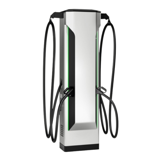
- Page 1 Edition 10/2023 OPERATING INSTRUCTIONS SICHARGE SICHARGE D Dispenser 8EM5907-2AA00-0AA1.01 siemens.com/sicharge-d...
- Page 2 Introduction Safety instructions SICHARGE D Description Dispenser Dispenser Transport and storage Operating Instructions Installation and mounting Commissioning Operation Behavior in the event of errors and error messages Maintenance and service Disposal Technical specifications Declaration of Conformity List of abbreviations and explanation of terms Checklist for commissioning 10/2023...
- Page 3 Note the following: WARNING Siemens products may only be used for the applications described in the catalog and in the relevant technical documentation. If products and components from other manufacturers are used, these must be recommended or approved by Siemens. Proper transport, storage, installation, assembly, commissioning, operation and maintenance are required to ensure that the products operate safely and without any problems.
-
Page 4: Table Of Contents
Table of contents Introduction............................About the operating instructions..................Basic information......................Open-source software....................... Safety instructions..........................General..........................2.1.1 Intended use, modifications to the device................. 2.1.2 Qualified personnel......................2.1.3 Protection against unauthorized opening................10 Hazards during transport, mounting, operation and maintenance........11 2.2.1 Personal protective equipment (PPE)................. - Page 5 Table of contents Description............................21 Product overview......................21 Interface to the SICHARGE D charging station..............22 Equipment and configuration options................23 Display elements and operator controls................23 Charging points........................ 26 Design of the dispenser..................... 28 Transport and storage........................29 General information......................29 Scope of delivery......................
- Page 6 Table of contents Commissioning........................... 57 Safety precautions before initial commissioning..............57 Switch on charging station....................57 Switching off the charging station..................58 Restarting the charging station..................Service mode........................59 Operation............................60 Safety instructions......................60 Starting the charging process.................... 61 Monitoring the charging process..................65 Stopping the charging process..................
-
Page 7: Introduction
Introduction About the operating instructions These operating instructions contain the information for the safe operation and intended use of the dispenser SICHARGE D. The operating instructions are aimed primarily at operators. Together with the SICHARGE D Operating Instructions, Repair Instruction (8EM5907-0AA00-4AA1) and the Software Manual (8EM5907 0AA00 4AA6), they form the basic documentation of the SICHARGE D. -
Page 8: Basic Information
Siemens accepts no liability for the use of the open source software over and above the intended program sequence, or for any faults caused by modifications to the software. -
Page 9: Safety Instructions
Safety instructions The safety instructions section describes the intended use by the target groups and potential dangers. General 2.1.1 Intended use, modifications to the device Intended use The SICHARGE D dispenser has up to two dedicated connections for charging the batteries of electric vehicles. -
Page 10: Qualified Personnel
Safety instructions 2.1 General The dispenser must be set up in accordance with the information in these operating instructions. Transport, installation, maintenance, cleaning, and normal operation must follow the instructions or procedures specified in these operating instructions. WARNING Danger due to missing or unrecognizable safety signs and warnings Missing or unrecognizable safety signs or warnings do not indicate that danger is not no longer present. -
Page 11: Hazards During Transport, Mounting, Operation And Maintenance
Safety instructions 2.2 Hazards during transport, mounting, operation and maintenance The dispenser is supplied with a replaceable locking cylinder (standard half cylinder (10/30) according to DIN 18252) and matching keys. Detailed instructions for replacing cylinders can be found in section 3.4 "Display elements and operator controls" (Page 23). Hazards during transport, mounting, operation and maintenance 2.2.1 Personal protective equipment (PPE) -
Page 12: Work Areas
Safety instructions 2.2 Hazards during transport, mounting, operation and maintenance 2.2.5 Work areas Danger of tripping or slipping. Keep work areas clean and tidy to prevent tripping and slipping. Accident hazards Avoid accidents, personal injury and damage to vehicles and the dispenser. Examples of accident hazards are: •... -
Page 13: Hazards In The Event Of Fire, Explosions And Emergencies
Safety instructions 2.4 Dangers due to electrical current Hazards in the event of fire, explosions and emergencies Fire and explosion protection Do not store or use highly flammable liquids that produce flammable vapors, such as gasoline or ethanol, in the proximity of the dispenser. Electrostatic charges or heat generated during charging can ignite explosive and flammable liquids. -
Page 14: Damaged Parts
Safety instructions 2.4 Dangers due to electrical current 2.4.2 Damaged parts Only use undamaged devices or parts Improper handing can damage devices. Hazardous voltages may be present on the cabinet or exposed components if devices are damaged. Dangerous voltages can result in severe injuries or death. -
Page 15: Electric Shock Due To Lack Of Grounding
Safety instructions 2.4 Dangers due to electrical current 2.4.4 Electric shock due to lack of grounding If the protective conductor connection is missing or incorrectly connected, high voltages may be present on exposed parts. Touching the parts can lead to severe injuries or death. To earth the dispenser, connect the protective conductor in conformance with regulations. -
Page 16: Dangers From Electric Fields
Safety instructions 2.6 Safety sign Dangers from electric fields 2.5.1 Pacemakers/implants No dangerous radiation emanates from the dispenser. Interference with pacemakers and implants is excluded. 2.5.2 Electromagnetic fields The dispenser meets the requirements of IEC 61851‑21‑2:2018: • Noise immunity: Class A (Industry) •... -
Page 17: Identification Of The Device
Safety instructions 2.7 Identification of the device Safety sign inside the dispenser Safety sign Meaning Warning of dangerous voltage Identification of the device The nameplate clearly identifies the dispenser and is located on the outside at the bottom of the left cabinet wall, and on the inside at the bottom of the front door (see Figure 1 "Position of nameplates"). - Page 18 Safety instructions 2.7 Identification of the device Information on the nameplate You can find the following information on the nameplate of the dispenser: Figure 2-2 Nameplate of the SICHARGE D dispenser Dispenser Operating Instructions, 10/2023, A5E52758387-AB...
-
Page 19: Safety Loop And Emergency Stop
See also Display elements and operator controls (Page 23) Industrial Security Siemens AG offers products and solutions with Industrial Security functions that support the secure operation of plants, systems, machines and networks. Implement and maintain the industrial security concept In order to protect plants, systems, machines and networks against cyber threats, it is necessary to implement –... - Page 20 Siemens’ products and solutions undergo continuous development to make them more secure. Siemens strongly recommends that product updates are applied as soon as they are available and that the latest product versions are used. Using versions that are obsolete or are no longer supported can increase the risk of cyber threats.
-
Page 21: Description
Description Product overview The dispenser adds additional fast-charging points to the SICHARGE D charging station. The dispenser supports the CCS2 DC charging standard. The following section describes the features of the dispenser. Performance features The dispenser adopts the performance features of the charging station and offers the following functionality: Charge performance: •... -
Page 22: Interface To The Sicharge D Charging Station
Description 3.2 Interface to the SICHARGE D charging station Compatibility Only vehicles that meet the requirements of the following standards can be charged at the dispenser: Table 3-1 Compatibility overview Type Standards CCS2 IEC 61851-23 IEC 62196 Mode 4 Communication DIN SPEC 70121 IEC 61851-24 ISO 15118 Interface to the SICHARGE D charging station... -
Page 23: Equipment And Configuration Options
Description 3.4 Display elements and operator controls Equipment and configuration options The following table shows the various selection and equipment options of the SICHARGE D dispenser. Article number Description 8EM5200 0AA10 0AA0 Without DC meter 8EM5200 1AA10 0AA0 With standard DC meter 8EM5200 2AA10 0AA0... - Page 24 Description 3.4 Display elements and operator controls LED strips The LED strips signal the state of the dispenser or the individual DC charging outlets. In this way, the user can recognize if the dispenser is free, the vehicle is fully charged or an error has occurred.
- Page 25 Description 3.4 Display elements and operator controls Locking system & replacing the lock cylinders The door locks and the door opener secure access to the inside of the dispenser. The locking cylinder is located on the left side next to the door. Deflect the locking cylinder and rotate the lever to the left to open the door.
-
Page 26: Charging Points
Description 3.5 Charging points Charging points The DC charging cables mounted on the dispenser have a CCS2 type charging plug. CCS plug (Combo 2) Figure 3-3 CCS plug (Combo 2) Table 3-3 Pin assignment of the CCS plug (Combo 2) Contact Control Pilot (CP) Communication signal between vehicle and charging station ①... - Page 27 Description 3.5 Charging points Temperature monitoring The DC charging cables have an integrated temperature sensor in the plug. The evaluation of these values ensures increased protection and secure transfer of the charging power. Correct and risk-free use is guaranteed. Performance features Table 3-4 Performance features CCS2 Characteristic Value...
-
Page 28: Design Of The Dispenser
Description 3.6 Design of the dispenser Design of the dispenser The cabinet is made of powder-coated steel. The standard cabinet paint color is RAL 9006. The following image shows the front view of the dispenser interior. ① Filters ② Controller section, protective devices and connection area ③... -
Page 29: Transport And Storage
Transport and storage General information Depending on the local conditions and customer requirements, two transport options are available. In general, transport from the factory and to the installation location is by truck. These options are available at the installation location: •... - Page 30 Transport and storage 4.1 General information To transport the dispenser to the installation site with a forklift, proceed as follows: 1. Drive into the load carrier with the forks on the longitudinal side. 2. Drive in until the forks are protruding at the other side. DANGER Tipping of the dispenser The dispenser may tip if transported improperly.
-
Page 31: Scope Of Delivery
Transport and storage 4.3 Road transport Scope of delivery The dispenser is supplied with an accessories kit box. The following is included in the accessories kit box: • 4 units crane lugs for mounting the dispenser • 4 units skirting • 2 units M6 hexagon screws (10 mm width across flats) •... - Page 32 Transport and storage 4.3 Road transport Figure 4-3 Packaging for road transport Load securing Have load securing carried out properly by qualified personnel. Position the packaging to fit tight on the truck. Use anti-slip mats under the complete pallet and lashing straps to secure the load.
-
Page 33: Air Transport
Transport and storage 4.4 Air transport Air transport Description of packaging If the dispenser is transported by air, the dispenser is placed on a reinforced and insulated wood pallet. Film protects the dispenser against dirt particles and moisture. The packaging consists of the following elements: •... -
Page 34: Sea Transport
Transport and storage 4.5 Sea transport Sea transport If the dispenser is transported by sea, the dispenser is placed on a reinforced and insulated wood pallet. An aluminum composite foil protects the dispenser inside the wooden box from moisture and salt air. The packaging consists of the following elements: •... - Page 35 Transport and storage 4.5 Sea transport Figure 4-5 Packaging for sea transport Dispenser Operating Instructions, 10/2023, A5E52758387-AB...
-
Page 36: Storage
Transport and storage 4.6 Storage Storage Proper storage of the dispenser is a requirement for safe operation of the device. NOTICE Damage to property due to improper storage If stored improperly, there is a risk of damage to the dispenser, for example, corrosion damage. -
Page 37: Installation And Mounting
Installation and mounting Preparation Tools list Ensure that before beginning work all required tools, materials and lifting gear is available. The following list does not claim to be complete: • Personal protective equipment (PPE) (Page 11) • Fall arrester (Page 11) •... -
Page 38: Installation Location
Declaration of Conformity (Page 80). Minimum clearances To enable operation and service and to ensure proper ventilation of the dispenser, you must maintain the following minimum clearances: Figure 5-1 Minimum clearances of SICHARGE D dispenser, top view Dispenser Operating Instructions, 10/2023, A5E52758387-AB... - Page 39 Installation and mounting 5.2 Installation location We recommend free-standing installation of the dispenser. When positioning two SICHARGE D devices next to each other, maintain double the minimum clearances between the two devices to ensure the cooling concept. Note the swivel range of the door. In addition, you need a minimum clearance of 20 cm between the top of the dispenser and the ceiling at the planned location.
- Page 40 Installation and mounting 5.2 Installation location Bumper To protect the dispenser from collisions by vehicles, impact protection is recommended (e.g. in the form of a bollard). Observe the swivel range of the door of 80 cm in front of the dispenser to allow the door to be fully opened. ①...
-
Page 41: Base Area
If height compensation is required, use the shims for height compensation. The following figure shows the dispenser from below, including the openings for inserting the cables. You can find more information about installation here: SICHARGE D dispenser technical draw ings (https://support.industry.siemens.com/cs/ww/en/view/109822247) Figure 5-3 Dispenser from below including openings... - Page 42 Figure 5-4 Top view of the base area Use the hole drilling template 8EM5905-0AA00-2AA3 to ensure that the drill holes and outlets of the connecting cables are positioned correctly. You can find more information about installation here: SICHARGE D dispenser technical draw ings (https://support.industry.siemens.com/cs/ww/en/view/109822247) Figure 5-5 Drilling template Insert M12 stud bolts after drilling.
- Page 43 Installation and mounting 5.3 Base area Depending on the installation location, ensure that the foundation depth is sufficient to guarantee frost-free conditions. Also observe the maximum permissible bending radii of the connecting cables you are using. Lay communication, control and auxiliary cables separately and protected from the power cables.
-
Page 44: Goods Acceptance
Installation and mounting 5.5 Installing the dispenser Goods acceptance 5.4.1 Checking the delivery for completeness and correctness Perform an incoming goods inspection as soon as the goods are delivered. Check the goods for completeness and correctness based on the delivery documents. 5.4.2 Checking the transport packaging Start the inspection of the transport packaging with the visual inspection. -
Page 45: Preparing Cables
Installation and mounting 5.5 Installing the dispenser 5.5.1 Preparing cables Prepare all the necessary conductors and connections before you start positioning the dispenser on the foundation. Cable routing Route the cables for the auxiliary power supply and communication separately and protected from the power cables. -
Page 46: Removing The Cable Gland Plate
Installation and mounting 5.5 Installing the dispenser 5.5.2 Removing the cable gland plate Removing the cable gland plate Remove the cable gland plate before positioning the dispenser. To do this, proceed as follows: 1. Open the device door. 2. Remove the four screws of the cable gland plate. 3. - Page 47 Installation and mounting 5.5 Installing the dispenser 4. Then attach the hoisting gear. 5. Loosen the screws between the dispenser and the load carrier. 6. Lift the dispenser vertically. Positioning the dispenser and inserting the cables Check the stud bolts in the foundation for the following points: •...
-
Page 48: Aligning And Mounting The Dispenser
Installation and mounting 5.5 Installing the dispenser 5.5.4 Aligning and mounting the dispenser After you have routed the cables into the cabinet, secure the dispenser to the base area. Required tools and fasteners To align and fasten the dispenser, you need the following tools: •... -
Page 49: Installing The Roof
Installation and mounting 5.5 Installing the dispenser 5.5.5 Installing the roof If necessary, use a ladder or platform to install the roof. Follow the instructions in section Fall arrester (Page 11). 1. Open the door. 2. Slide the roof left to right at the back underneath the provided metal guides. 3. -
Page 50: Installing Baseboards
Installation and mounting 5.5 Installing the dispenser Figure 5-10 Cable gland plate 5.5.7 Installing baseboards Mount the baseboards as follows: 1. Insert the two side baseboards into the spring nipples on the rear baseboard to form a U shape. Slide this U shape into position below the dispenser. 2. -
Page 51: Connecting The Dispenser
Installation and mounting 5.6 Connecting the dispenser Connecting the dispenser 5.6.1 Safety instructions The installer is responsible for the electrical connection of the charging station and dispenser. Connect the overall charging station in accordance with the relevant rules (on conductor cross-section, fuses, ground connection, etc.). - Page 52 Installation and mounting 5.6 Connecting the dispenser Preparing the conductors of the cable You must prepare the individual conductors of the cable in order to connect them properly. Proceed as follows: WARNING Observe the five safety rules according to DIN EN 50110-1:2013 Working on live parts can result in severe injuries and death.
-
Page 53: Connecting The Dc Conductors
Installation and mounting 5.6 Connecting the dispenser 5.6.3 Connecting the DC conductors The SICHARGE D charging station supplies power to the dispenser with a separate DC circuit for each charging point. The connection points in the charging station are described in the circuit diagram and the operating instructions of the SICHARGE D charging station. - Page 54 Installation and mounting 5.6 Connecting the dispenser Preparing conductors You must prepare the individual conductors in order to connect them properly. Proceed as follows: WARNING Observe the five safety rules according to DIN EN 50110-1:2013 Working on live parts can result in severe injuries and death. Only work on the electrical equipment when it is in a de-energized state.
-
Page 55: Connecting The Signal Cable
Installation and mounting 5.6 Connecting the dispenser 5.6.4 Connecting the signal cable The safety circuit with the SICHARGE D charging station has been implemented using a shielded signal cable. Connecting the 7-pin signal cable (shielded) There are additional signal conductors coming from SICHARGE D. Connect the conductors according to the electrical circuit diagram. -
Page 56: Connecting The Communication Cable
Installation and mounting 5.6 Connecting the dispenser 5.6.5 Connecting the communication cable The dispenser requires an Ethernet connection to the charging station for communication and for remote access from the backend systems. The connection point in the charging station is described in the circuit diagram and the operating instructions of the charging station. -
Page 57: Commissioning
Commissioning Safety precautions before initial commissioning Before initial commissioning, verify the overall charging station and the dispenser in accordance with DIN VDE 0100‑600 or comparable standard/guideline. This includes, in particular, the measurement of protective conductor impedance and isolation resistances. Also check the fuse protection of the charging station on the mains side. Ensure that the charging cables have not become loose during transport. -
Page 58: Switching Off The Charging Station
Commissioning 6.3 Switching off the charging station Automatic starting of the charging station If voltage is applied to the charging station, it will automatically start up. Wait until the charging station is fully started. The LED strips light up white initially during startup. In ready- to-operate state, the LED strips are lit green and the display on the SICHARGE D shows the start menu. -
Page 59: Restarting The Charging Station
Commissioning 6.5 Service mode Restarting the charging station You can restart the charging station either on site or via remote access from the SICHARGE Configuration Backend SCB. When a door is opened, 2 further buttons appear on the SICHARGE D display next to the notice about the door. The charging station is shut down with "Restart"... -
Page 60: Operation
Operation The SICHARGE charging station and dispenser are operated via the touch screen on the charging station. The individual operator options and menu guidance are described in this section. The illustrations may differ slightly depending on the firmware of the device. Safety instructions Observe the following safety instructions for safe operation of the charging station. -
Page 61: Starting The Charging Process
Operation 7.2 Starting the charging process Starting the charging process Getting started The language is selected by tapping on the respective greeting in the desired language. If you tap at any other point instead, the default language or the last selected language is automatically selected (highlighted in white, in this case, English). - Page 62 Operation 7.2 Starting the charging process The available charging ports and their states are then displayed. Tap on the charging outlet where you want to charge your vehicle. The arrangement of the outlets on the screen also corresponds to the actual arrangement at the charging station. In the following example, the two CCS charging cables of the dispenser are to the right of the SICHARGE D.
- Page 63 On this website you can then download the e-receipt for your transaction to your end device. Registration with an EMSP backend is not necessary, in contrast to contract-based charging. NOTE Siemens is not responsible for the "e-Receipt" function. Make sure that the infrastructure for receipt transmission is available. Dispenser Operating Instructions, 10/2023, A5E52758387-AB...
- Page 64 Operation 7.2 Starting the charging process Plugging in the charging cable If the charging cable is not yet connected to the vehicle, you are prompted after the authentication to connect the plug to your vehicle. The charging process starts automatically. Figure 7-3 Connecting the charging cable Communication between the vehicle and charging station begins.
-
Page 65: Monitoring The Charging Process
Operation 7.3 Monitoring the charging process Monitoring the charging process You can monitor a successfully started charging process via the touch screen. The type and amount of information depends on the charging point and whether tariff information is available from the OCPP backend. To view more information, you can navigate using the arrows. -
Page 66: Stopping The Charging Process
Operation 7.4 Stopping the charging process If, for example, you need to authenticate yourself with an RFID card, scanning the card brings you immediately to the charging screen. Stopping the charging process Automatic stopping The following scenarios result in automatic termination of the charging process: •... -
Page 67: Calling The Help Function
Operation 7.5 Calling the help function Depending on the setting in the SCB, the user must authenticate again for confirmation. All instructions are displayed on the touch screen. After successful stopping of the charging process, the display changes again. The user sees a summary of the charging process in the display. -
Page 68: Behavior In The Event Of Errors And Error Messages
Behavior in the event of errors and error messages In the event of an error, the charging station automatically performs error diagnostics. In the event of an error, it sends one or more error messages to the OCPP backend and the SCB. The error messages in the SCB have a very high level of detail and help with error analyses in the event of service. - Page 69 Behavior in the event of errors and error messages 8.1 Error message "Emergency Stop was triggered" Error message "Emergency Stop was triggered" With the Emergency Stop triggered, the display shows the following error message. Figure 8-1 Error message "The emergency stop switch has been activated" Emergency Stop As part of the Emergency Stop, the power supply of all charging processes is switched off.
-
Page 70: Error Message "Charging Station Out Of Service
The operator is informed via a message to the OCPP backend that support from Siemens Service is required. This service can first analyze the problem remotely via the SCB. This message contains additional information about the exact cause of the error. -
Page 71: Error Message "Outlet Out Of Service
Behavior in the event of errors and error messages 8.3 Error message "Outlet out of service" Error message "Outlet out of service" If the control system detects that only one charging outlet is affected by an error case, only this charging outlet is locked selectively. A complete failure of the charging station does not occur. -
Page 72: Reinsertion Of Charging Cable" Error Message
Behavior in the event of errors and error messages 8.4 "Reinsertion of charging cable" error message "Reinsertion of charging cable" error message If the charging cable does not lock correctly when first inserted, the charging process is not started. The user is asked to plug in the charging cable again. The following error message appears on the display. -
Page 73: Maintenance And Service
Maintenance and service Safety instructions To guarantee the safety of persons and material assets during maintenance and service of the overall charging station, observe the following safety information. WARNING Electric shock from live parts Electrical systems have live parts during operation. If the system has not been disconnected from the power supply before maintenance work is performed inside the station, death, serious injury or damage to property may occur. -
Page 74: Maintenance Plan
SICHARGE D charging station and dispenser (e.g. high dust exposure). Checking the charging station Follow the inspection steps from the document with order number 8EM5907-0AA00-7AA3 "Preventive Maintenance Checklist (https://support.industry.siemens.com/cs/us/en/view/109814289)". Dispenser Operating Instructions, 10/2023, A5E52758387-AB... -
Page 75: Dispenser Maintenance
Maintenance and service 9.3 Dispenser maintenance Dispenser maintenance 9.3.1 Cleaning the cabinet WARNING Electric shock due to water ingress Water entering the charging station can damage the charging station. If the unit is damaged, dangerous voltages may be present on the cabinet or exposed components, which can cause serious injury or death if touched. -
Page 76: Replacing An Air Filter
Table 9-1 Required tools Charging cable Width across flats 400 A (boost mode) CCS SW45 Spare parts The order number of the spare part list is: 8EM5907-0AA00-2AA6. You can download the spare part list here (https://support.industry.siemens.com/cs/ww/en/view/109814736). Dispenser Operating Instructions, 10/2023, A5E52758387-AB... -
Page 77: Disposal
Disposal Environmental protection and the conservation of resources are a high priority for us. Global environmental management according to ISO 14001 ensures adherence to laws and sets high standards for this. Environmentally friendly design, technical safety and health protection are solid targets even during the development of our products. The charging station is ROHS-compliant. -
Page 78: Technical Specifications
Technical specifications DC output Unit Value Rated power Depending on the connected SICHARGE D charging station 160 to 300, including upgradability Voltage range 150 … 1000 Outlet options DC: 2 x CCS2 charging points Maximum current of the connected char 400 (air-cooled cable) ging cables Cable length Dynamic power allocation Same as connected SICHARGE D charging station Standby power consumption ≤ 100... - Page 79 Technical specifications General specifications Metering options Optional: DC meter per charging point Accuracy class B according to EN 50470-3:2016 and EN 50470-1:2016 Remote management • Remote access • Over-the-air (OTA) software updates • External charging management with Modbus TCP (via the connected SICHARGE D charging station) Distance from SICHARGE D charging sta...
-
Page 80: Declaration Of Conformity
The SICHARGE D dispenser complies with the harmonized European standards (EN) for dispensers published in the official gazettes of the European Union. Safekeeping location of the declaration of conformity Siemens AG keeps the EU Declaration of Conformity of the dispenser available for the relevant authorities at the following location: Siemens AG... -
Page 81: List Of Abbreviations And Explanation Of Terms
List of abbreviations and explanation of terms Abbreviations The following abbreviations are used in these instructions: Abbreviation Term Alternating Current Combined Charging System Direct Current ELMS External load management system Human Machine Interface OCPP Open Charge Point Protocol Polyethylene Protective Earth RFID Radio Frequency Identification Device SICHARGE Configuration Backend... -
Page 82: Checklist For Commissioning
Checklist for commissioning Table B-1 Checklist Work step Done Check installation location Check sufficient lighting Check minimum clearances: • side: 1 m • rear: 1 m • top: 0.20 m Prepare & check the base area Base area level? Base area dry? Carrying capacity sufficient for total weight of the dispenser? Position of the DC cable gland suitable? Check dimensional accuracy of fastening points... - Page 83 Checklist for commissioning Work step Done Installing the dispenser Loosen screw connection with transport carrier Lift dispenser from transport carrier and position it over base area Insert cables and lower the charging station/dispenser Fasten the charging station/dispenser to the base area, tightening torque according to the bolt anchor used Drill holes in the cable gland plate and insert cable glands, take Ethernet and control cables into consideration, if applicable...
-
Page 84: Index
Index Abbreviations, 81 Declaration of Conformity, 80 Dispenser Positioning, 46 Securing, 48 Bumper, 40 Disposal, 77 Disposal Packaging material, 77 Dispenser, 77 Cabinet Dynamic power distribution, 22 Cleaning, 75 Charging monitoring, 65 Charging cable Electrical protective devices, 22 Cleaning, 75 Emergency stop Charging station Error message, 68... - Page 85 Index Product overview, 21 Qualified personnel, 10 Replacing an air filter, 76 Safety instructions, 8 Connecting, 51 Operation, 60 Safety rules for electrical work, 14 Safety sign, 16 Self-checks & health monitoring, 22 Terms, 81 Dispenser Operating Instructions, 10/2023, A5E52758387-AB...
- Page 86 More information https://www.siemens.com Siemens Aktiengesellschaft Smart Infrastructure eMobility Siemenspromenade 10 91058 Erlangen, Germany...
Need help?
Do you have a question about the SICHARGE D Dispenser and is the answer not in the manual?
Questions and answers